WB21LMB
WB21LMC
Please read this manual carefully before operating your set and retain it for future reference.
Wall Mount Bracket
Safety and Reference
OWNER’S MANUAL
Printed in Korea
www.lg.com
Copyright 2021 LG Electronics Inc. All Rights Reserved.
*MFL71772403*
(2108-REV03)
2
ENGLISH_index
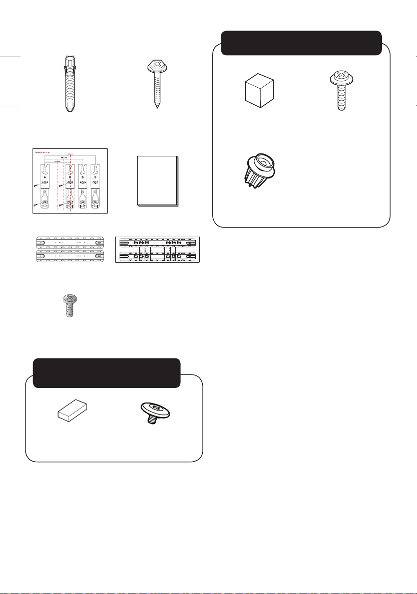
Accessories
Wall mount xing
anchors 8pcs.
Wall mount xing
screws 8 pcs.
Guide paper Installation Manual
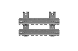
Wall mounting
supporter
Assembly Guide Paper
Wall mounting
supporter screw 8 EA
(M5 x L6)
TV protection
cushionA 2 pcs.
TV xing screwsA
2 pcs.
3-1) 13mm (0.5 inches) (Concrete wall)
2-1) 19mm (0.7 inches) (Wood stud)
3-2) 39 mm (1.5 inches) (Concrete wall)
2-2) 45mm (1.7 inches) (Wood stud)
TV protection
cushionB
2 pcs.
Guide Spacer
Fixing Screws 2 pcs.
(M6 x L45)
Guide Spacer
2 pcs.
Precautions for Safety
- Professional installers should read this manual
carefully to ensure proper installation.
- Professional installers should forward this manual
to customers after installation and encourage them
to read and store it in a convenient place for future
reference.
After reading the installation manual, keep it in a
convenient place for future reference.

3
ENGLISH_index
Warning
Ask a professional installer appointed by the
store for installation of the product.
Installation by someone other than a professional
installer is extremely dangerous and may result in
personal injury.
Contact a professional installer appointed by the
store prior to moving or replacing the product
after installation.
Installation is a technical task and safety issues may
arise if an individual attempts to install or move the
product personally.
When installing the product on a wall, do not
hang the power line or signal cables from the
back of the TV.
This can damage the cords, resulting in a re, elec-
trical shock or malfunction of the product.
Do not install the product in an unstable site that
cannot withstand its weight.
If the installation site lacks sufcient rigidity, the
product may fall and cause personal injury.
Do not hang on the product or subject it to
severe impact after installation.
Doing so may cause the product to fall and cause
personal injury.
Caution
Install the product according to the instructions
in the installation manual.
Failure to install the product according to the
instructions in the installation manual can result in
serious personal injury or product damage.
Be sure to have at least four people when install-
ing the product or adjusting the product’s height.
Attempting to perform installation or adjustments
personally may result in personal injury or damage
to the product.
Make sure a wall is available prior to proceeding
with installation. Make use of the anchors and
screws provided with the product.
Use of any unauthorized anchors or screws may not
support the product's weight, which poses safety
risks.
When drilling in the wall for installation, be sure
to use drill bits and drills of the specied diame-
ter. Follow the instructions for the hole depth.
Drilling and installing the product in ways other
than specied in the installation manual may result
in an unstable installation and potential safety
issues.
Do not wipe the product with a wet towel or use
any heating equipment or humidier under the
place where the product is installed.
Liquid water or vapor may enter the product and
excessive heat may cause re, electric shock, or
malfunction.

4
ENGLISH_index
Do not install the product near a re sprinkler
or detector, a place where vibration or shock
may occur or near a high-voltage wire or power
source.
Unplug the product’s power cord from the wall
outlet before installing.
Installing the product while the power cord is
plugged in may result in electric shock or re.
Do not install the product with bare hands. Be
sure to wear work gloves.
Attempting installation without work gloves may
cause personal injury.
Connect the product with the supplied cable.
Use of an unauthorized cable may result in
damage by friction with the wall. Make sure to
use the supplied cable gender. (This may vary by
model.)
Before Installation
• Do not use the product for any purpose other than
installing the TV on a wall.
• Avoid product damage and safety accidents caused
by careless installing or use of improper or unauthor-
ized wall mount.
• Follow the instructions in the installation manual for
a convenient installation of the wall mount.
• Immediately discontinue installation and contact
the service center if you cannot fully understand the
installation process.
Use a professional installer if any installation issues
remain after the inquiry.
• Installation of this product on a concrete wall or
wood stud is recommended. Installation on walls
made of other types of plasterboard, plywood, brick,
etc., is not recommended since there is a greater
chance the product will fall.
• When installing the Full Contact Wall Mount, the TV
may not be contacted rmly against the wall due to
some wall conditions.
• Install the product only on a vertical wall.
Do not install on a tilted wall that exceeds building
standards or on the heavily titled wall or ceiling.
LG is not responsible for problems caused by improp-
er installation of the product, e.g., heavily tilted walls
and ceilings.
• Check the enclosed accessories before installation.
We are not responsible for any lost or damaged
accessories after the inner packaging is opened.
• When an infant or small child swallows the enclosed
accessories, various safety accidents such as choking
may occur. Keep the enclosed accessories out of the
reach of infants and children.
• When tightening screws, tighten until fully snug.
Avoid using excessive force when tightening the
screws. Doing so may damage the wall and product
or reduce the rigidity or performance of the product.
• Avoid installing a TV that exceeds the specied
tensile load, and do not allow any external force to
be applied to the product.
• Avoid accidents by using work tools with care during
installation.
• After installing the product, ensure its use in close
contact with a wall.
If the product is not positioned against a wall, the
product may be unstable or damaged.
Tools for Installation
- “+” shaped screwdriver (manual or electric)
- level
- drill
- Ø8mm drill bit for concrete or Ø4mm drill bit for
steel
5
ENGLISH_index
How to install
• The appearance of tools may differ from the en-
closed images.
• Always consult a professional when installing a wall
mount.
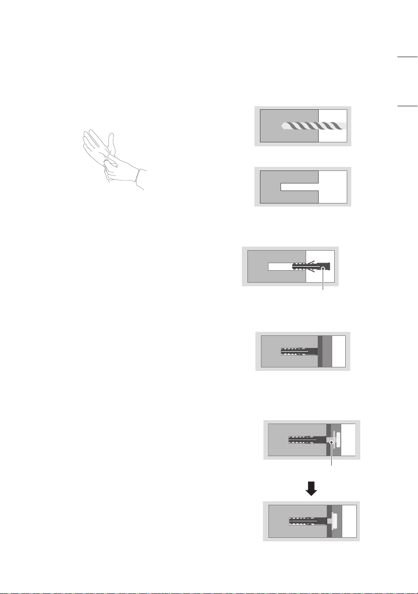
1. Wearing gloves
2. Fastening Anchors and Screws
• Check that the material and thickness of the wall
and nishing material comply with the installation
manual. Before beginning the mounting process, you
must be sure the wall is able to support the weight
of the TV.
• Should use the enclosed anchors and screws on
crack free concrete walls.
• If the wall is not made of concrete, the wall mount
must be installed on a rigid support. Never install
the product on a plasterboard or wall made of paper
or medium-density berboard (MDF). In this case,
make sure that the wall material can withstand the
weight of the TV, and x the anchor screws to the
retaining wall (concrete) or wooden support behind
the nishing material. Since the anchors provided
with this product may not be suitable for your wall
material, be sure to check with a professional before
attempting installation.
• Other unspecied walls must be capable of support-
ing pullout loads of over 70 kgf (154.3 lbf) (686 N)
and shear loads of over 100 kgf (220.4 lbf) (980 N)
per fastener.
• Use an Ø 8 mm drill bit for concrete and a hammer
(impact) drill or Ø 4 mm drill bit for wood stud to
drill holes.
For installation on concrete
wall
1. Drill holes in anchor locations with a drill bit of Ø 8
mm to a depth of 80 mm (3.1 inches) to 100 mm
(3.9 inches).
2. Clean the drilled holes.
3. Insert the enclosed anchors for xing the wall
mount into the holes. (Use a hammer when insert-
ing anchors.)
Anchors for xing the wall mount
4. Push the wall mount support closely toward the
wall to match the hole locations.
5. Tighten screws for xing the wall mount to the
holes. At this time, tighten the screws with the
torque more than 45 kgf/cm (39.0 lbf/in) to 60 kgf/
cm (52.0 lbf/in).
Screws for xing the wall mount
6
ENGLISH_index
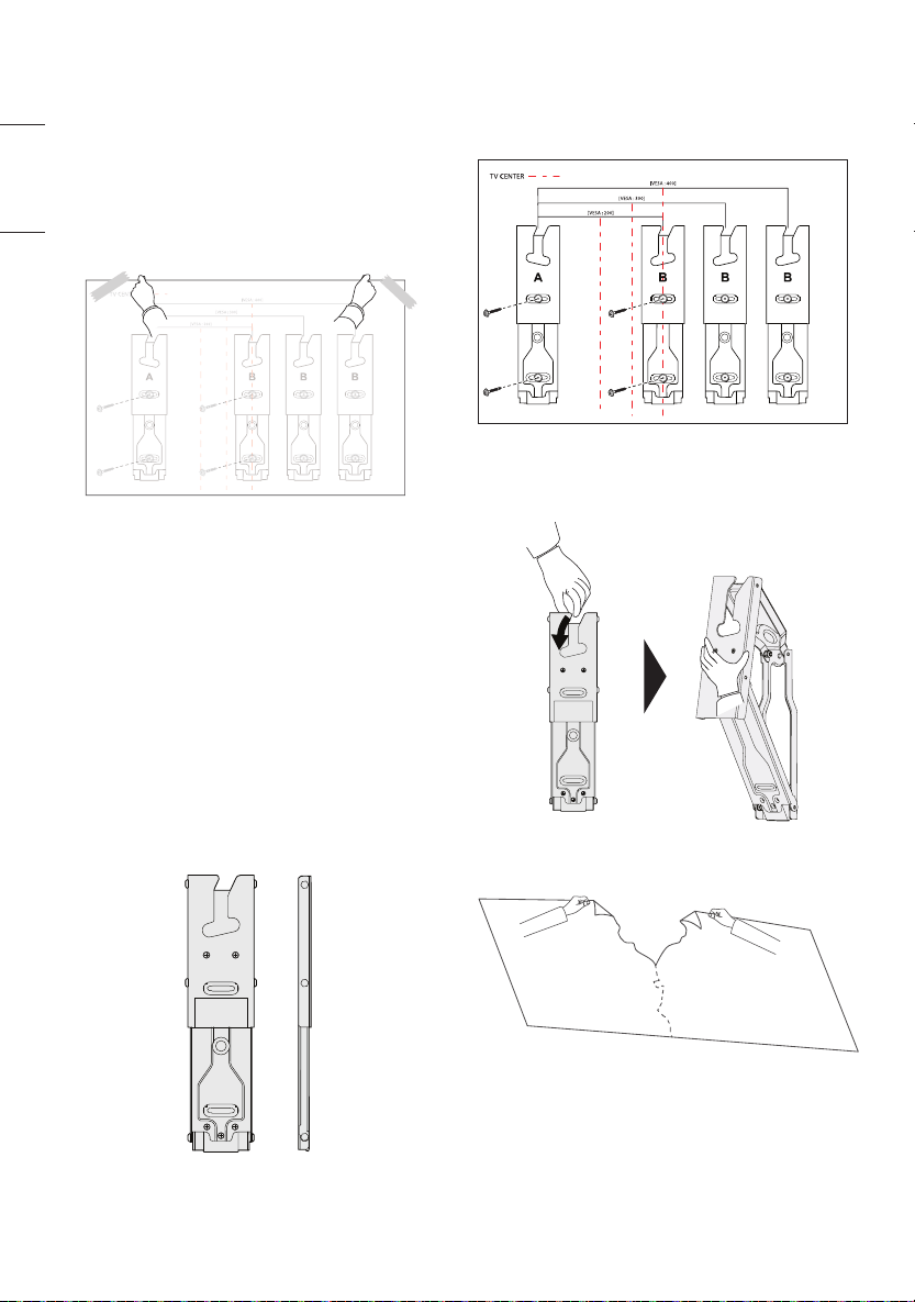
1. Attaching the guide paper to the
wall
Attach the guide paper to the wall when determining
the TV’s installation site.
- Ensure the guide paper is level when attaching it to
the wall.
- Attach it by referring to the outer line of the TV and
the location of the TV center.
2. Installing the Wall Mount Support
• Install A on the left and B on the right according to
the markings on the wall mount.
• Refer to the following picture to x the wall mount
support.
• Use a level to verify that the wall mount is positioned
horizontally.
• Fix the wall mount screws: one at the top and one at
the bottom.
• Use a Phillips screwdriver (manual or powered) to
tighten the screws so that the wall mount support is
rmly xed to the wall surface.
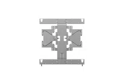
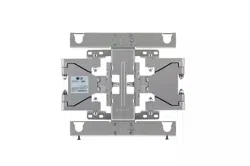
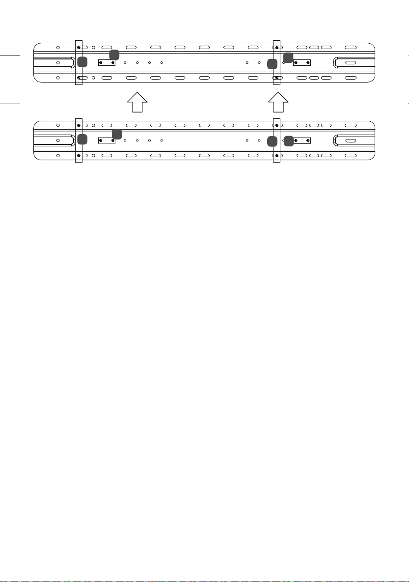
1. Check the shape of the wall mount in the picture.
2. Install the wall mount support at the location
marked on the guide paper.
- Install after checking the VESA size for the model
you purchased.
3. In the order, unfold the wall mount by pulling the
parts indicated in the picture.
4. Remove the guide paper.
7
ENGLISH_index
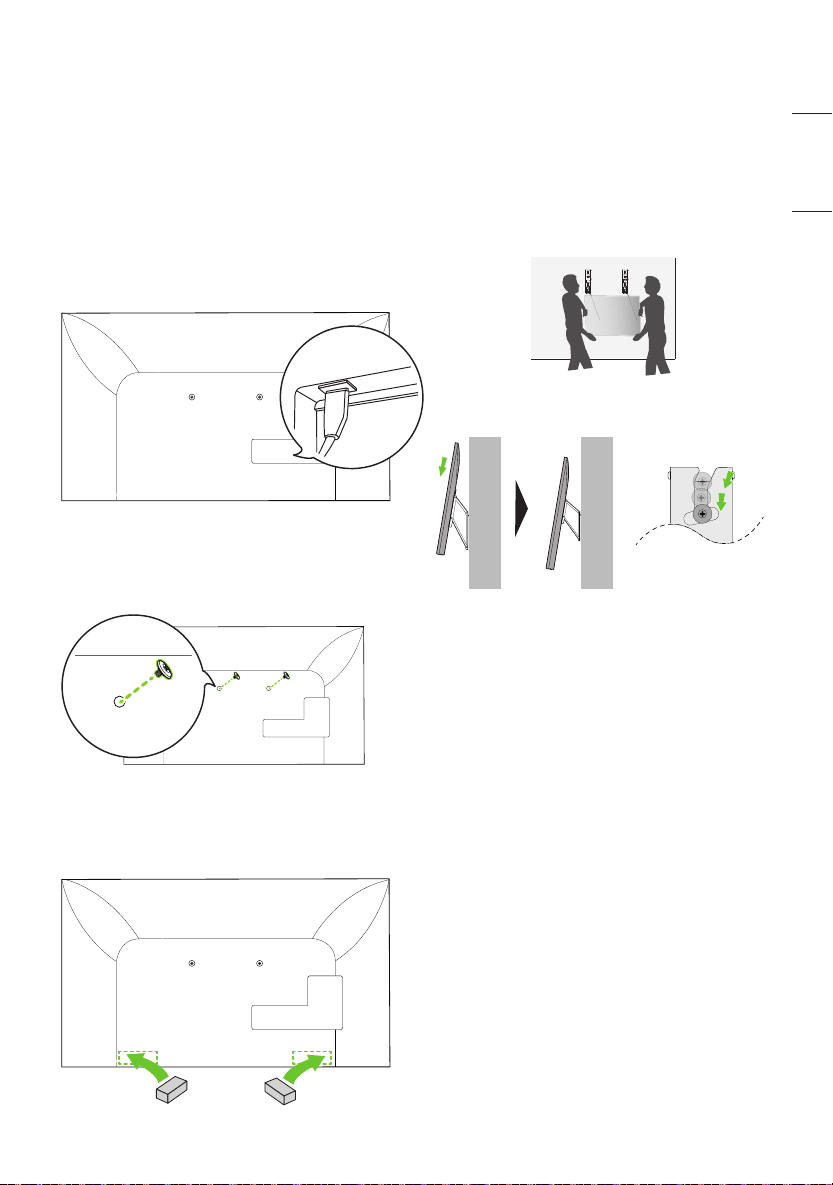
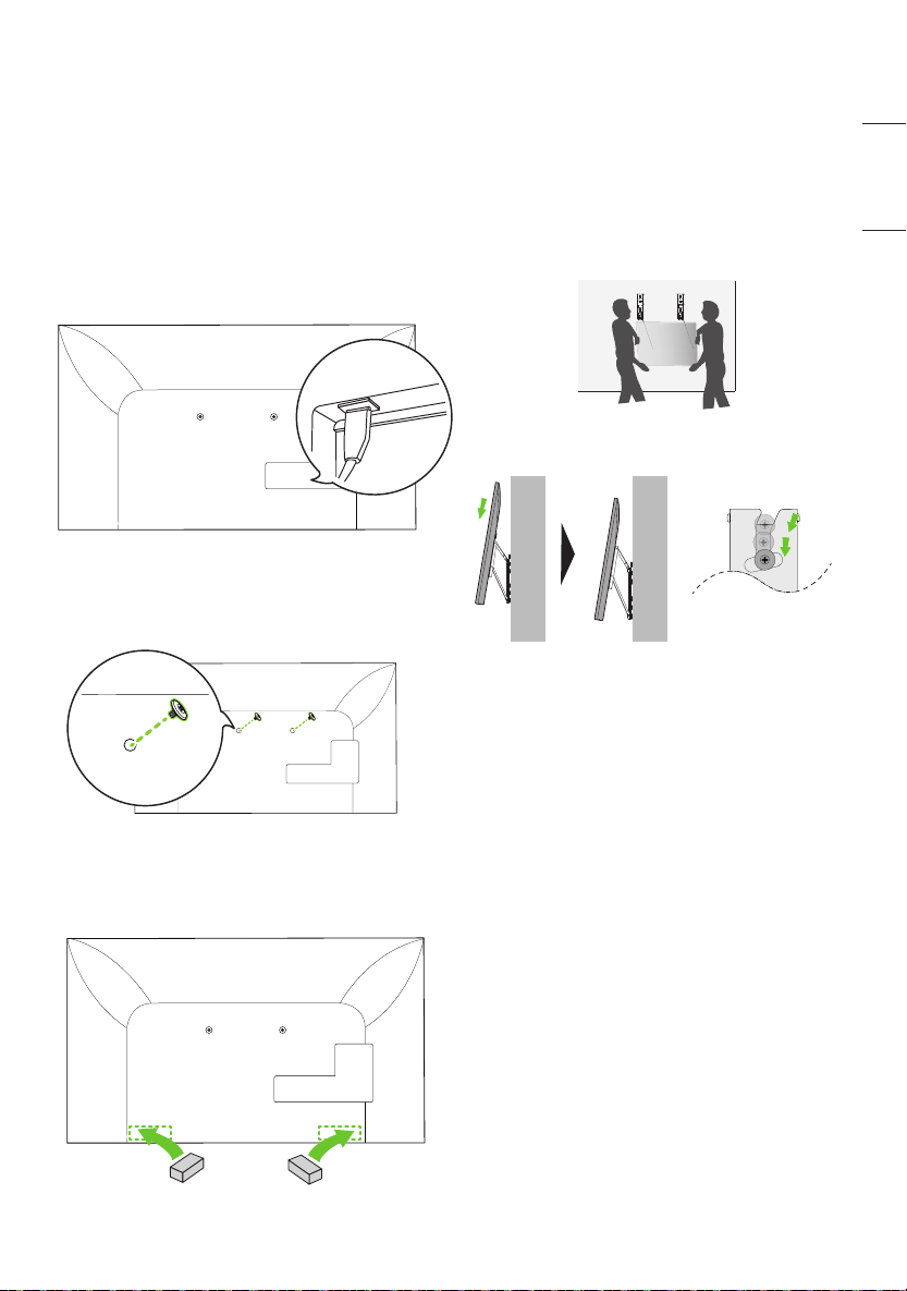
3. Attaching the TV to the Wall
Support
Depending on the model, those with horizontal termi-
nals are recommended to follow Method 3-2
models without horizontal terminals should follow
Method 3-1 and, when installing by Method 3-2,
it is recommended to use the side terminal for HDMI
& USB.
3-1) Separation distance between TV and
wall: 13 mm (0.5 inches)
1. Fasten the enclosed TV xing screws to both sides
of the top of VESA on the TV.
2. Attach the enclosed TV protective cushion A to
the bottom of the at surface behind the TV. (The
location may differ depending on the model.)
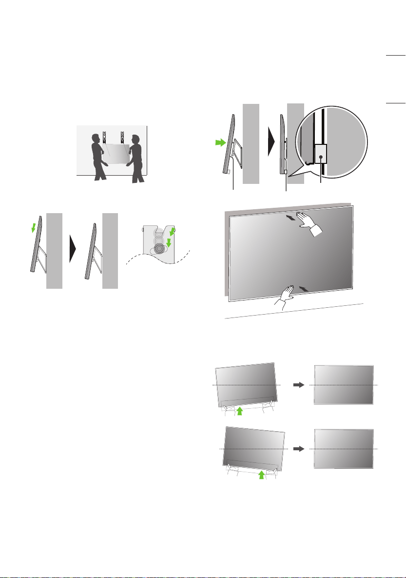
3. After attaching the TV to the mount on the wall,
fasten the screws xed to the TV to the wall mount.
Caution: Ensure two or more people work together
when mounting the TV. (If the product is lifted
by one person, it may fall and result in injury or
damage.)
Be careful not to trap the power cord between the
wall mount bracket and the TV when mounting
the TV. (If the power cord becomes trapped, it may
result in product damage.)
8
ENGLISH_index
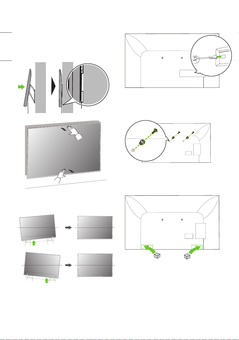
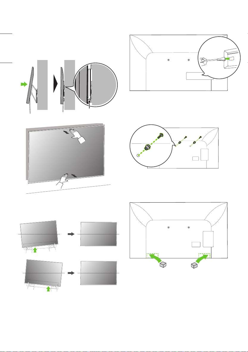
4. Push the TV close to the wall. Be sure to gently
push the upper and lower parts of the TV so that
the pushing doesn’t affect the TV. Gently push the
upper center of the TV once again until it’s com-
pletely pressed against the wall.
Caution: Do not apply excessive force to the screen.
(Doing so can damage the screen.)
13mm (0.5 inches)
5. Adjust the product’s position by hand so it’s hori-
zontal. Hold the left and right bottom sides of the
TV and adjust it to the desired direction.
3-2) Separation distance between TV and
wall: 39mm (1.5 inches)
1. Fasten the enclosed TV guide spacers and guide
spacer xing screws to both sides of VESA.
2. Attach the enclosed TV protective cushion B to
the bottom of the at surface behind the TV. (The
location may differ depending on the model.)
9
ENGLISH_index
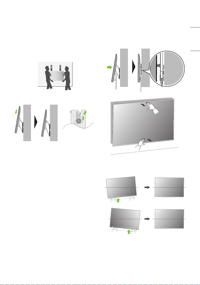
3. After attaching the TV to the mount on the wall,
fasten the screws xed to the TV to the wall mount.
Caution: Ensure two or more people work together
when mounting the TV. (If the product is lifted
by one person, it may fall and result in injury or
damage.)
Be careful not to trap the power cord between the
wall mount bracket and the TV when mounting
the TV. (If the power cord becomes trapped, it may
result in product damage.)
4. Push the TV close to the wall. Be sure to gently
push the upper and lower parts of the TV so that
the pushing doesn’t affect the TV. Gently push the
upper center of the TV once again until it’s com-
pletely pressed against the wall.
Caution: Do not apply excessive force to the screen.
(Doing so can damage the screen.)
39mm (1.5 inches)
5. Adjust the product’s position by hand so it’s hori-
zontal. Hold the left and right bottom sides of the
TV and adjust it to the desired direction.
10
ENGLISH_index
4. Plugging Additional Cables in
While Using the TV
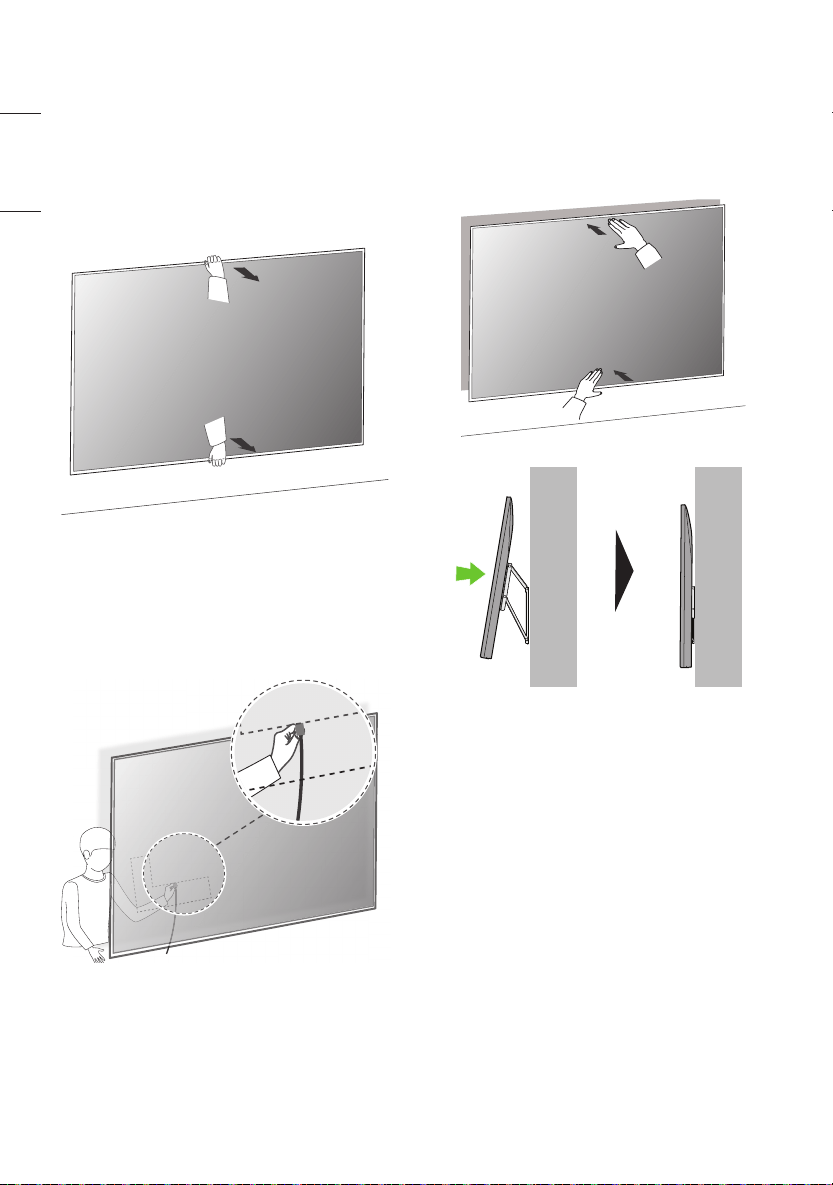
1. While holding the lower part of the TV, pull the up-
per side of the TV so it does not affect the product.
Gently pull the upper and lower parts of the TV and
check the position to connect the cable from the
side.
2. Check the position of the cable from the side and
plug it into the TV. Position your body as close to
the wall as possible behind the TV and organize the
cables using the holder. (The location of the cable
connection terminal may differ depending on the
model.)
3. Push the TV close to the wall. Be sure to gently
push the upper and lower parts of the TV so that
the pushing doesn’t affect the TV. Gently push the
upper center of the TV once again until it’s com-
pletely pressed against the wall.
Caution: Do not apply excessive force to the screen.
(Doing so can damage the screen.)
11
ENGLISH_index
For installation on wood stud
1. Check the type of wall where the installation will take place.
- When installing on a wooden wall, mark the left and right center positions of the wood studs.
2. Assemble by referring to the assembly guide paper which is provided as an accessory.
3. Check the screw xing positions by marking the Wall mounting supporter screw points indicated by the left
and right centers of the wood studs.
Wall Mounting Supporter Point
Wall Mounting Bracket Point
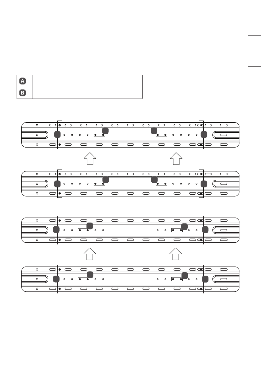
Japan
- When installing on a wooden wall (VESA Size 200)
A
A
A
A
B
B
B
B
- When installing on a wooden wall (VESA Size 300)
A
A
A
A
B
B
B
B
12
ENGLISH_index
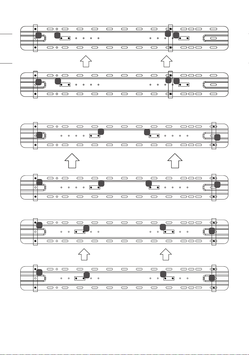
- When installing on a wooden wall (VESA Size 400)
A
A
A
A
B
B
B
B
Australia
- When installing on a wooden wall (VESA Size 200)
A
A
A
A
B
B
B
B
- When installing on a wooden wall (VESA Size 300)
A
A
A
A
B
B
B
B

13
ENGLISH_index
- When installing on a wooden wall (VESA Size 400)
A
A
A
A
B
B
B
B
North America
- When installing on a wooden wall (VESA Size 200)
B
B B
B
A
A
A
A
- When installing on a wooden wall (VESA Size 300)
A
A
A
A
B
B
B
B
14
ENGLISH_index
- When installing on a wooden wall (VESA Size 400)
A
A
A
A
B
B
B
B
15
ENGLISH_index
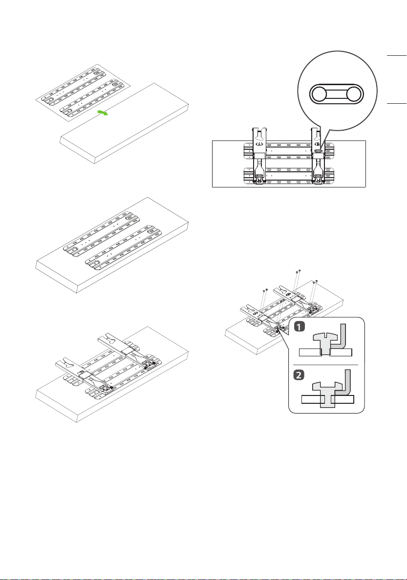
1. How to Assemble Support
1. Place the assembly guide on the box.
2. Align the Wall mounting supporter on the assembly
guide paper with the outer line.
3. Place the wall mount support on the Wall mounting
supporter.
4. Align the hole in the wall mount support with the
hole in the Wall mounting supporter.
5. Insert the wall mount support screw into the hole in
the wall mount support and Wall mounting support-
er. (Tighten the screw while holding the wall mount
support with your hand.)
1) Loosely tighten the screws, turning just 2 to 3
times before placing the wall mount.
2) Tighten until it is completely tight.
16
ENGLISH_index
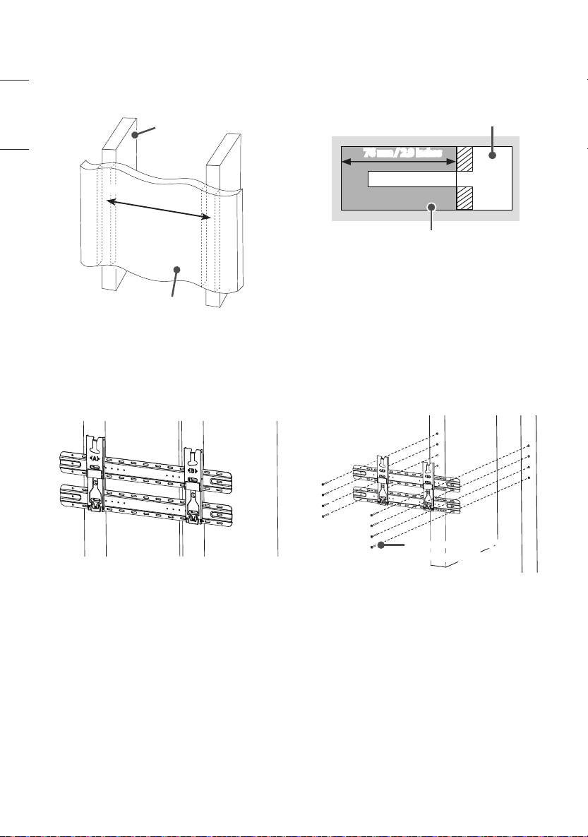
Japan
1. Use the stud nder to locate and mark the center
of the wall stud.
Drywall
Wood stud
455 mm (17.9 inches)
2. After aligning the wall mount and Wall mounting
supporter assembly (wall mount assembly) on
the wall where the center of the wood stud is
marked, mark the position of the screw and
remove the wall mount assembly. (Use a level to
make sure that the screw marks are horizontal.)
3. Using a Ø 4 mm wood drill bit, drill a hole 76 mm
(2.9 inches) or deeper into the screw locations
marked on the wall for the wall mount. (Clean the
drill holes)
Drywall
Wood stud
76 mm / 2.9 inches
4. Position the wall mount assembly so that it ts
over the drilled holes. Tighten the wall mount
screws for the Wall mounting xing screws into
the drill holes. At this time, tighten the screws so
that the wall, wall mounting assembly, and wall
mount support screws are in close contact with
each other.
- Be careful, since excessive tightening can damage
drywalls.
- When tightening the screws, use a Phillips head
screwdriver. (manual or electric)
Screws for Fixing The Wall
Mounting Supporter
17
ENGLISH_index
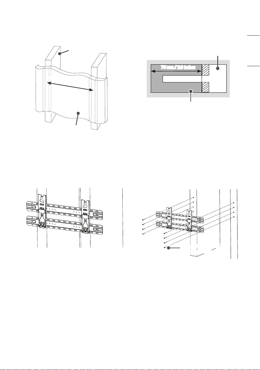
Australia
1. Use the stud nder to locate and mark the center
of the wall stud.
Drywall
Wood stud
600 mm (23.6 inches)
2. After aligning the wall mount and Wall mounting
supporter assembly (wall mount assembly) on
the wall where the center of the wood stud is
marked, mark the position of the screw and
remove the wall mount assembly. (Use a level to
make sure that the screw marks are horizontal.)
3. Using a Ø 4 mm wood drill bit, drill a hole 76 mm
(2.9 inches) or deeper into the screw locations
marked on the wall for the wall mount. (Clean the
drill holes)
Drywall
Wood stud
76 mm / 2.9 inches
4. Position the wall mount assembly so that it ts
over the drilled holes. Tighten the wall mount
screws for the Wall mounting xing screws into
the drill holes. At this time, tighten the screws so
that the wall, wall mounting assembly, and wall
mount support screws are in close contact with
each other.
- Be careful, since excessive tightening can damage
drywalls.
- When tightening the screws, use a Phillips head
screwdriver. (manual or electric)
Screws for Fixing The Wall
Mounting Supporter

18
ENGLISH_index
North America
1. Use the stud nder to locate and mark the center
of the wall stud.
Drywall
Wood stud
406 mm (15.9 Inches)
2. After aligning the wall mount and Wall mounting
supporter assembly (wall mount assembly) on
the wall where the center of the wood stud is
marked, mark the position of the screw and
remove the wall mount assembly. (Use a level to
make sure that the screw marks are horizontal.)
3. Using a Ø 4 mm wood drill bit, drill a hole 76 mm
(2.9 inches) or deeper into the screw locations
marked on the wall for the wall mount. (Clean the
drill holes)
Drywall
Wood stud
76 mm / 2.9 inches
4. Position the wall mount assembly so that it ts
over the drilled holes. Tighten the wall mount
screws for the Wall mounting xing screws into
the drill holes. At this time, tighten the screws so
that the wall, wall mounting assembly, and wall
mount support screws are in close contact with
each other.
- Be careful, since excessive tightening can damage
drywalls.
- When tightening the screws, use a Phillips head
screwdriver. (manual or electric)
Screws for Fixing The Wall
Mounting Supporter
19
ENGLISH_index
2. Attaching the TV to the Wall
Support
Depending on the model, models with horizontal ter-
minals are recommended to follow Method 2-2
models without horizontal terminals should follow
Method 2-1 and, when installing by Method 2-2,
it is recommended to use the side terminal for HDMI
& USB.
2-1) Separation distance between TV and
wall: 19 mm (0.7 inches)
1. Fasten the enclosed TV xing screws to both sides
of the top of VESA on the TV.
2. Attach the enclosed TV protective cushion A to
the bottom of the at surface behind the TV. (The
location may differ depending on the model.)
3. After attaching the TV to the mount on the wall,
fasten the screws xed to the TV to the wall mount.
Caution: Ensure two or more people work together
when mounting the TV. (If the product is lifted
by one person, it may fall and result in injury or
damage.)
Be careful not to trap the power cord between the
wall mount bracket and the TV when mounting
the TV. (If the power cord becomes trapped, it may
result in product damage.)
20
ENGLISH_index
4. Push the TV close to the wall. Be sure to gently
push the upper and lower parts of the TV so that
the pushing doesn’t affect the TV. Gently push the
upper center of the TV once again until it’s com-
pletely pressed against the wall.
Caution: Do not apply excessive force to the screen.
(Doing so can damage the screen.)
19 mm (0.7 inches)
5. Adjust the product’s position by hand so it’s hori-
zontal. Hold the left and right bottom sides of the
TV and adjust it to the desired direction.
2-2) Separation distance between TV and
wall: 45mm (1.7 inches)
1. Fasten the enclosed TV guide spacers and guide
spacer xing screws to both sides of VESA.
2. Attach the enclosed TV protective cushion B to
the bottom of the at surface behind the TV. (The
location may differ depending on the model.)
21
ENGLISH_index
3. After attaching the TV to the mount on the wall,
fasten the screws xed to the TV to the wall mount.
Caution: Ensure two or more people work together
when mounting the TV. (If the product is lifted
by one person, it may fall and result in injury or
damage.)
Be careful not to trap the power cord between the
wall mount bracket and the TV when mounting
the TV. (If the power cord becomes trapped, it may
result in product damage.)
4. Push the TV close to the wall. Be sure to gently
push the upper and lower parts of the TV so that
the pushing doesn’t affect the TV. Gently push the
upper center of the TV once again until it’s com-
pletely pressed against the wall.
Caution: Do not apply excessive force to the screen.
(Doing so can damage the screen.)
45mm (1.7 inches)
5. Adjust the product’s position by hand so it’s hori-
zontal. Hold the left and right bottom sides of the
TV and adjust it to the desired direction.
22
ENGLISH_index
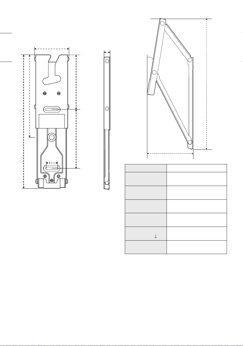
Specications
[Unit: mm(inches)]
73.7 (2.9)
13 (0.5)
285.9 (11.2)
176.5 (6.9)
117 (4.6)
126 (4.9)
25 (0.9)
93.3 (3.6)
9.2˚
267.8 (10.5)
Model Name WB21LMB
Width
(mm(inches))
73.7 (2.9)
Height
(mm(inches))
285.9 (11.2)
Depth
(mm(inches))
13 (0.5)
Product Weight
(kg(lbs))
0.6 (1.3) x 2
Screws Distance
(mm) (65’’ )
200/300/400
Max. Tensile Load
(kg(lbs))
50 (110.2)
23
ENGLISH_index
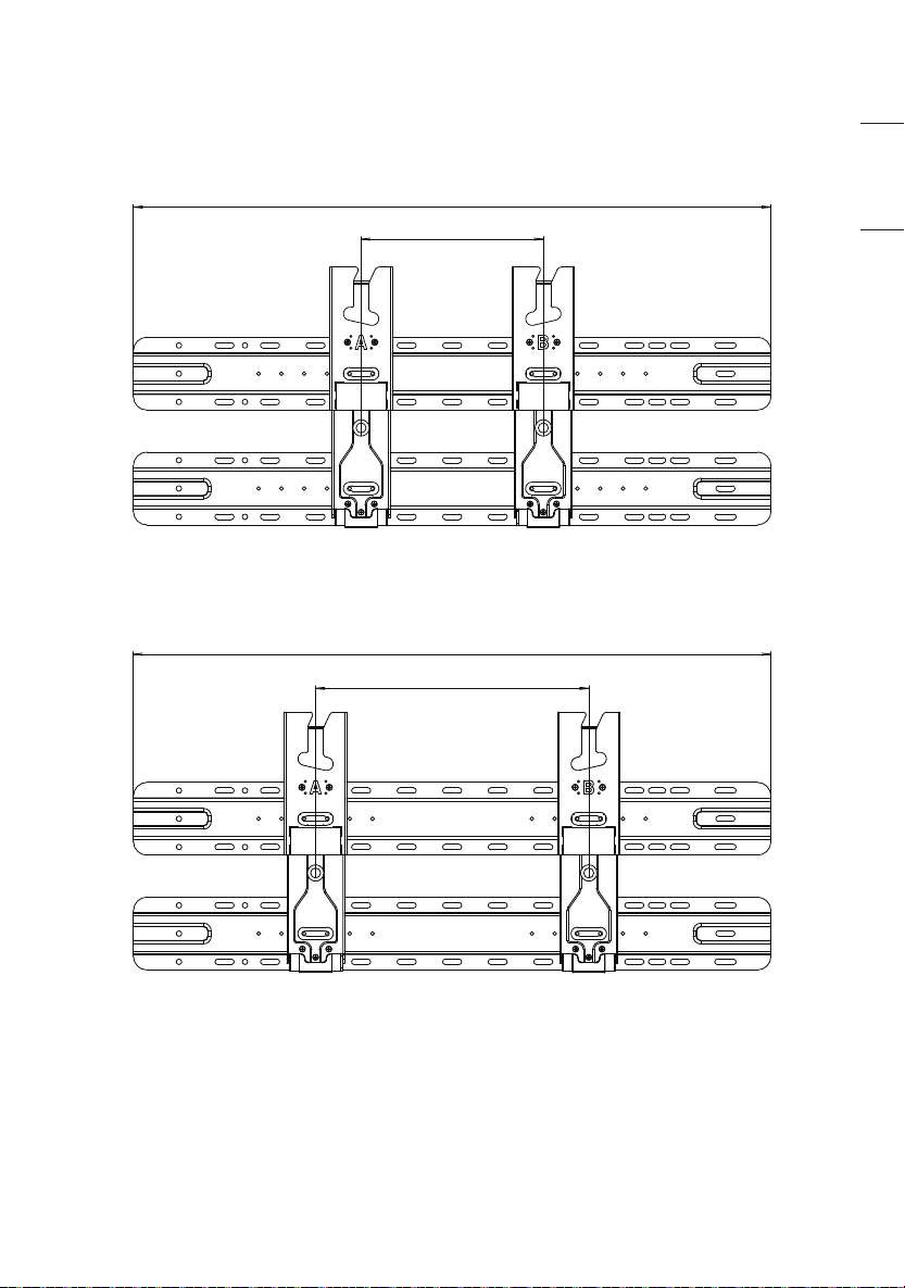
Australia, Japan
When not removing the wall mount support
[VESA 200]
700 (27.5)
200 (7.8)
[VESA 300]
700 (27.5)
300 (11.8)
24
ENGLISH_index
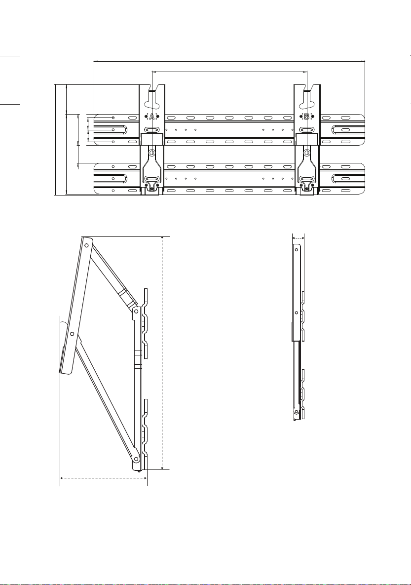
99.3 (3.9)
9.2˚
267.8 (10.5)
19 (0.7)
[VESA 400]
700 (27.5)
285.9 (11.2)
206 (8.1)
77 (3.0)
46 (1.8)
80 (3.1)
400 (15.7)
31 (1.2)
31 (1.2)
25
ENGLISH_index
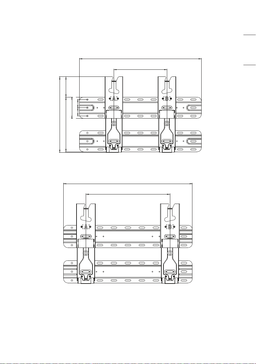
North America
When not removing the wall mount support
[VESA 200]
80 (3.1)
206 (8.1)
285.9 (11.2)
77 (3.0)
31 (1.2)
460 (18.1)
200 (7.8)
31 (1.2)
[VESA 300]
460 (18.1)
300 (11.8)
26
ENGLISH_index
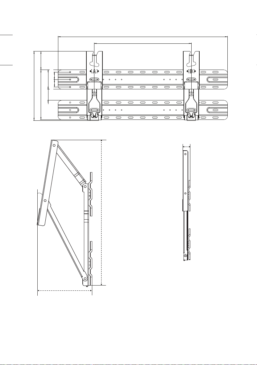
[VESA 400]
700 (27.5)
400 (15.7)
285.9 (11.2)
206 (8.1)
77 (3.0)
46 (1.8) 80 (3.1)
31 (1.2) 31 (1.2)
99.3 (3.9)
9.2˚
267.8 (10.5)
19 (0.7)
27
ENGLISH_index
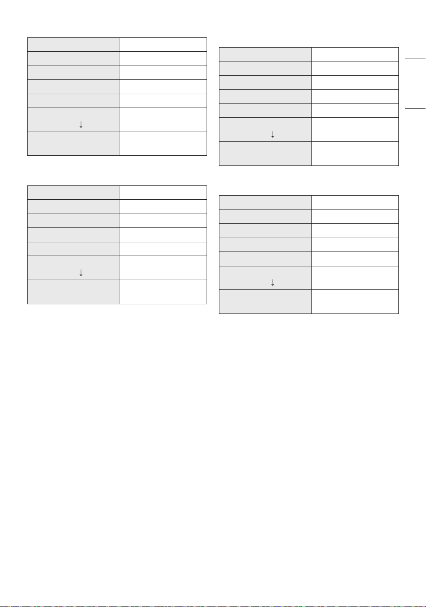
[When removing the wall mount support]
Model Name WB21LMB
Width (mm(inches)) 73.7 (2.9)
Height (mm(inches)) 285.9 (11.2)
Depth (mm(inches)) 13 (0.5)
Product Weight (kg(lbs)) 1.2 (2.6)
Screws Distance (mm)
(65’’ )
200/300/400
Max. Tensile Load
(kg(lbs))
50 (110.2)
<Australia, Japan>
[When not removing the wall mount support]
Model Name WB21LMB
Width (mm(inches)) 700 (27.5)
Height (mm(inches)) 285.9 (11.2)
Depth (mm(inches)) 19 (0.7)
Product Weight (kg(lbs)) 3.6 (7.9)
Screws Distance (mm)
(65’’ )
200/300/400
Max. Tensile Load
(kg(lbs))
50 (110.2)
<North America>
[When not removing the wall mount support]
Model Name WB21LMB
Width (mm(inches)) 460 (18.1)
Height (mm(inches)) 285.9 (11.2)
Depth (mm(inches)) 19 (0.7)
Product Weight (kg(lbs)) 2.8 (6.1)
Screws Distance (mm)
(65’’ )
200/300
Max. Tensile Load
(kg(lbs))
50 (110.2)
<North America>
[When not removing the wall mount support]
Model Name WB21LMC
Width (mm(inches)) 700 (27.5)
Height (mm(inches)) 285.9 (11.2)
Depth (mm(inches)) 19 (0.7)
Product Weight (kg(lbs)) 3.6 (7.9)
Screws Distance (mm)
(65’’ )
200/300/400
Max. Tensile Load
(kg(lbs))
50 (110.2)