ENGLISH_index
*MFL721284032405REV00*
Safety and Reference
OWNER’S MANUAL
WB24GDB
Wall Mount
Bracket
Please read this manual carefully be-
fore operating your set and retain it for
future reference.
www.lg.com
Copyright © 2024 LG Electronics Inc.
All Rights Reserved.
Printed in Korea
The model and serial number of the
product are located on the back and on
one side of the product. Record them
below in case you ever need service.
Model
Serial No.
2
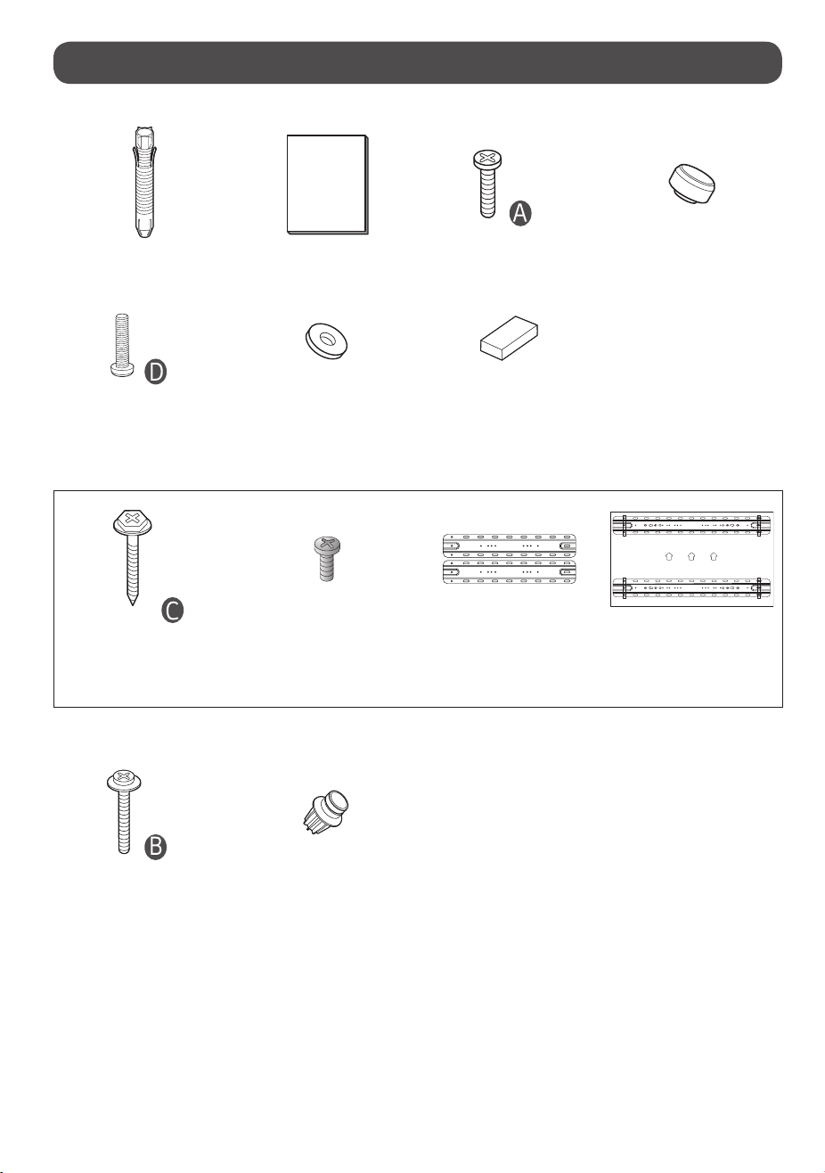
Accessories
x 4
Wall mount xing anchors 6 pcs. Owner’s Manual
Guide Spacer Fixing Screws A 4 pcs.
(M8 x L18)
Guide Spacer A 4 pcs.
x 2
Levelling screws 2 pcs. Circular sheet 4 pcs. TV protection cushion 4 pcs.
Depending on country
Wall mount xing screws
(M5 x L65)
6 pcs. (North Ameraica)
10 pcs. (Except North America)
Wall mounting supporter screw
8 pcs. (M5 x L6)
Wall mounting supporter VESA guide paper
When using rear inputs
x 4
Guide Spacer Fixing Screws B 4 pcs.
(M8 x L44)
Guide Spacer B 4 pcs.

3
Precautions for Safety
- Professional installers should read this manual carefully to ensure proper
installation.
- Professional installers should forward this manual to customers after
installation and encourage them to read and store it in a convenient place
for future reference.
- After reading the installation manual, keep it in a convenient place for
future reference.
Ask a professional installer appointed by the store for installation
of the product.
Installation by someone other than a professional installer is extremely
dangerous and may result in personal injury.
Contact a professional installer appointed by the store prior to
moving or replacing the product after installation.
Installation is a technical task and safety issues may arise if an individual
attempts to install or move the product personally.
When installing the product on a wall, do not hang the power
line or signal cables from the back of the TV.
This can damage the cords, resulting in a re, electrical shock or malfunc-
tion of the product.
Do not install the product in an unstable site that cannot
withstand its weight.
If the installation site lacks sucient rigidity, the product may fall and
cause personal injury.
Do not hang on the product or subject it to severe impact after
installation.
Doing so may cause the product to fall and cause personal injury.
Install the product according to the instructions in the installa-
tion manual.
Failure to install the product according to the instructions in the installa-
tion manual can result in serious personal injury or product damage.
Be sure to have at least four people when installing the product
or adjusting the product’s height.
Attempting to perform installation or adjustments personally may result
in personal injury or damage to the product.
Make sure a wall is available prior to proceeding with instal-
lation. Make use of the anchors and screws provided with the
product.
Use of any unauthorized anchors or screws may not support the product’s
weight, which poses safety risks.
When drilling in the wall for installation, be sure to use drill bits
and drills of the specied diameter. Follow the instructions for
the hole depth.
Drilling and installing the product in ways other than specied in the
installation manual may result in an unstable installation and potential
safety issues.
Do not wipe the product with a wet towel or use any heating
equipment or humidier under the place where the product is
installed.
Liquid water or vapor may enter the product and excessive heat may cause
re, electric shock, or malfunction.
Do not install the product near a re sprinkler or detector, a place
where vibration or shock may occur or near a high-voltage wire
or power source.
Unplug the product’s power cord from the wall outlet before
installing.
Installing the product while the power cord is plugged in may result in
electric shock or re.
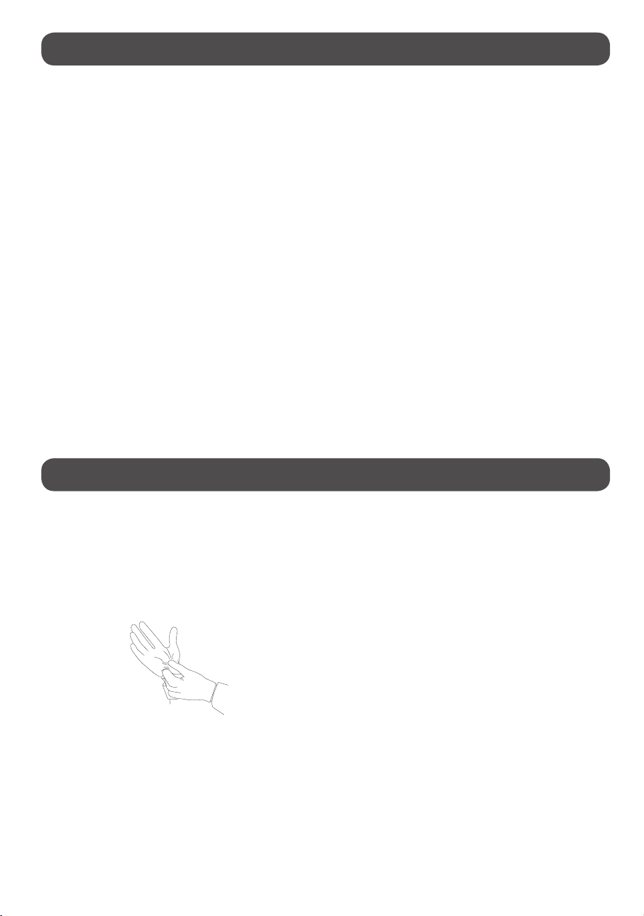
Do not install the product with bare hands. Be sure to wear work
gloves.
Attempting installation without work gloves may cause personal injury.
Connect the product with the supplied cable. Use of an unauthor-
ized cable may result in damage by friction with the wall. Make
sure to use the supplied cable gender. (This may vary by model.)
4
Before Installation
• Do not use the product for any purpose other than installing the TV on a
wall.
• Avoid product damage and safety accidents caused by careless installing or
use of improper or unauthorized wall mount.
• Follow the instructions in the installation manual for a convenient
installation of the wall mount.
• Immediately discontinue installation and contact the service center if you
cannot fully understand the installation process.
Use a professional installer if any installation issues remain after the
inquiry.
• Installation of this product on a concrete wall or wood stud is
recommended. Installation on walls made of other types of plasterboard,
plywood, brick, etc., is not recommended since there is a greater chance
the product will fall.
• Install the product only on a vertical wall.
Do not install on a tilted wall that exceeds building standards or on the
heavily titled wall or ceiling.
LG is not responsible for problems caused by improper installation of the
product, e.g., heavily tilted walls and ceilings.
• Check the enclosed accessories before installation. We are not responsible
for any lost or damaged accessories after the inner packaging is opened.
• When an infant or small child swallows the enclosed accessories, various
safety accidents such as choking may occur. Keep the enclosed accessories
out of the reach of infants and children.
• When tightening screws, tighten until fully snug. Avoid using excessive
force when tightening the screws. Doing so may damage the wall and
product or reduce the rigidity or performance of the product.
• Avoid installing a TV that exceeds the specied tensile load, and do not
allow any external force to be applied to the product.
• Avoid accidents by using work tools with care during installation.
Tools for Installation
- “+” shaped screwdriver (manual or electric)
- 8mm spanner
- level
- drill
- Ø8mm drill bit for concrete or Ø4mm drill bit for steel
How to install
How to install
• The appearance of tools may dier from the enclosed images.
• Always consult a professional when installing a wall mount.
1. Wearing gloves
2. Fastening Anchors and Screws
• Check that the material and thickness of the wall and nishing material
comply with the installation manual. Before beginning the mounting
process, you must be sure the wall is able to support the weight of the TV.
• Should use the enclosed anchors and screws on crack free concrete walls.
• If the wall is not made of concrete, the wall mount must be installed on a
rigid support. Never install the product on a plasterboard or wall made of
paper or medium-density berboard (MDF). In this case, make sure that
the wall material can withstand the weight of the TV, and x the anchor
screws to the retaining wall (concrete) or wooden support behind the
nishing material. Since the anchors provided with this product may not be
suitable for your wall material, be sure to check with a professional before
attempting installation.
• Other unspecied walls must be capable of supporting pullout loads of
over 70 kgf (154 lbf) (686 N) and shear loads of over 100 kgf (220.5 lbf )
(980 N) per fastener.
• Use an Ø 8 mm drill bit for concrete and a hammer (impact) drill or Ø 4 mm
drill bit for wood stud to drill holes.
5
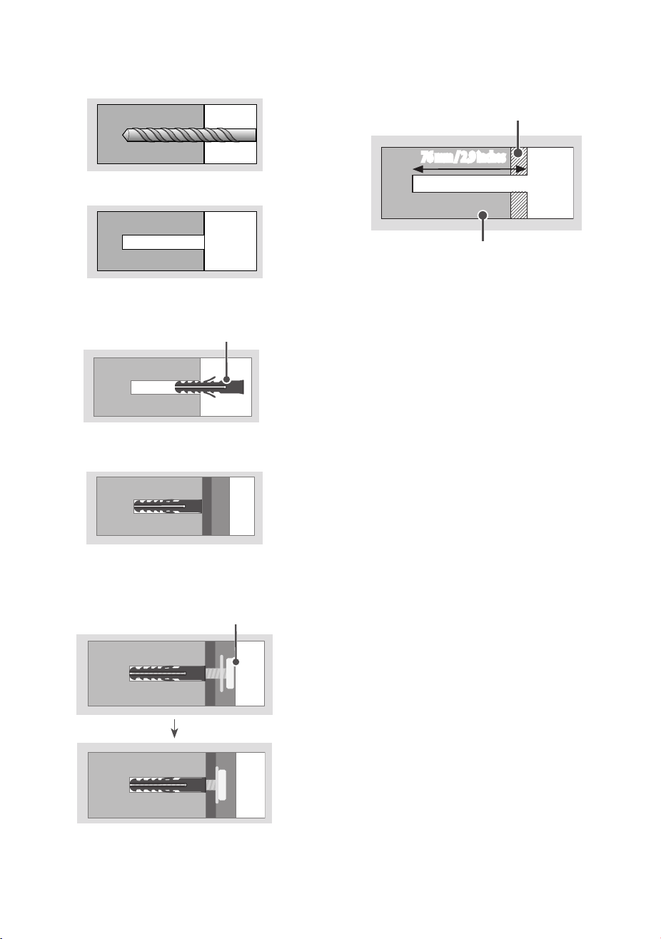
For installation on concrete wall
1. Drill holes in anchor locations with a drill bit of Ø 8 mm to a depth of
80 mm (3.1 inches) to 100 mm (3.9 inches).
2. Clean the drilled holes.
3. Insert the enclosed anchors for xing the wall mount into the holes.
(Use a hammer when inserting anchors.)
Anchors for xing the wall mount
4. Push the wall mount support closely toward the wall to match the
hole locations.
5. Tighten screws for xing the wall mount to the holes. At this time,
tighten the screws with the torque more than 45 kgf/cm (39 lbf/in) to
60 kgf/cm (52 lbf/in).
Screws for xing the wall mount
For installation on wood stud
Use the Ø 4 mm drill bit for wood to drill holes with the depth of 76 mm (2.9
inches). (Clean the drilled hole.)
Drywall
Wood stud
76 mm / 2.9 inches
Without using the wall mounting anchor, fasten the wall mounting screw
directly to the wood stud.
6
3. How to install the wall mount
bracket (Depending on country)
Australia, New Zealand, Japan
1. Check the wall type before mounting.
- When mounting on a wooden wall, check the screw xing spots on the
wall according to the Wall Mounting Supporter Point.
2. Mark the wall mounting location using the VESA guide paper provided.
3. Marking the Screw Fixing Spots on the Wall Using the VESA Guide
Paper.
When mounting to wooden stud
1. Locate and mark the centers of the wall studs using a stud nder.
Australia, New Zealand
Drywall
Wood stud
600 mm/23.6 Inches
Japan
Drywall
Wood stud
455 mm/17.9 Inches
2. After aligning the wall mounting bracket on the wall where the center
of the wood stud is marked, mark the location of the screws and then
remove the wall mounting bracket. (Use a level to make sure your
screw marks are level.)
3. Use the Ø 4 mm drill bit for wood to drill holes with the depth of 76
mm (2.9 Inches) or above where the wall mounting screw location is
marked on the wall. (Clean the drilled hole.)
Drywall
Wood stud
76 mm /2.9 Inches
7
4. Tighten the wall mounting screws for the wall bracket on the drilled
hole.
- At this time, tighten the screw so that the wall, wall mounting bracket
and the wall mounting screw are pressed against one another.
(Drywall can be damaged when tightened with excessive force, please
be careful.)
- When tightening the screw use the + driver (manual or motorized)
or 8 mm wrench.
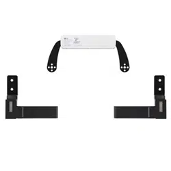
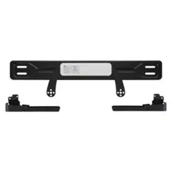
4. Installing the Wall Mount Bracket
• After aligning the wall mount bracket at the desired position, mark the
positions for the xings, and remove the bracket.
• Fix the bracket in place, as shown in the image.
• Use a level to ensure the wall mount is level.
• If it is not possible to tighten the screw in the marked position, you can
do so in the nearest position. However, do not change more than one
position in the designated locations.
• Secure two wall-mounting screws on each side of the upper part and
one on each side of the lower part.
• Use a “+” driver (manual or electric) or an 8 mm spanner to fully tighten
the screws, ensuring the wall, bracket, and screws are in complete
contact.
x 6

8
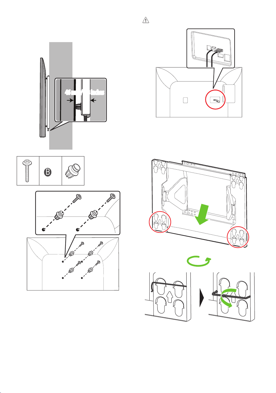
1. Attach the included guide spacer A and guide spacer xing screw A to
the VESA holes.
19mm
19mm / 0.7 Inches
x 4
* The rear of the TV
For models with circular recesses around the VESA holes of the TV
Attach the included guide spacer A and guide spacer xing screw A to the
VESA holes using a circular sheet.
19mm
19mm / 0.7 Inches
x 4
* The rear of the TV
9
When using rear inputs
Attach the included guide spacer B and guide spacer xing screw B to the
VESA holes.
19mm
46mm / 1.8 Inches
x 4
* The rear of the TV
• Only use guide spacer B when utilising the rear inputs. This may cause
improper installation of the wall mount bracket.
2. Lift the lock spring upward before installing the wall mount on the
wall.
10
3. After pressing the TV against the wall-mounted bracket, fasten the
screws attached to the TV into the wall mount.
• Ensure two or more people work together when mounting the TV.
• If the product is lifted by one person, it may fall and result in injury or
damage.
• Be careful not to trap the power cord between the wall mount bracket
and the TV when mounting the TV.
• If the power cord becomes trapped, it may result in product damage.
VESA mounting positions
VESA 600 mm x 400 mm (23.6 Inches x 15.7 Inches)
VESA 500 mm x 400 mm (19.6 Inches x 15.7 Inches)
5. Attaching the TV to the Wall
Mount Bracket
• Place the product on the wall in the direction of the arrow with the
guide spacers in the wall mounting bracket. Attach the lower part rst,
then attach the upper part by slightly lifting up the set.
• Make sure that the product is xed securely in place by pulling on the
bottom of the set.
• If speakers have been attached to the product, lift it by holding the
product itself, not the speakers.
• Make sure that the power cord does not get trapped between the wall
mounting bracket and the set during installation.
• A trapped power cord may cause damage to the product.
11
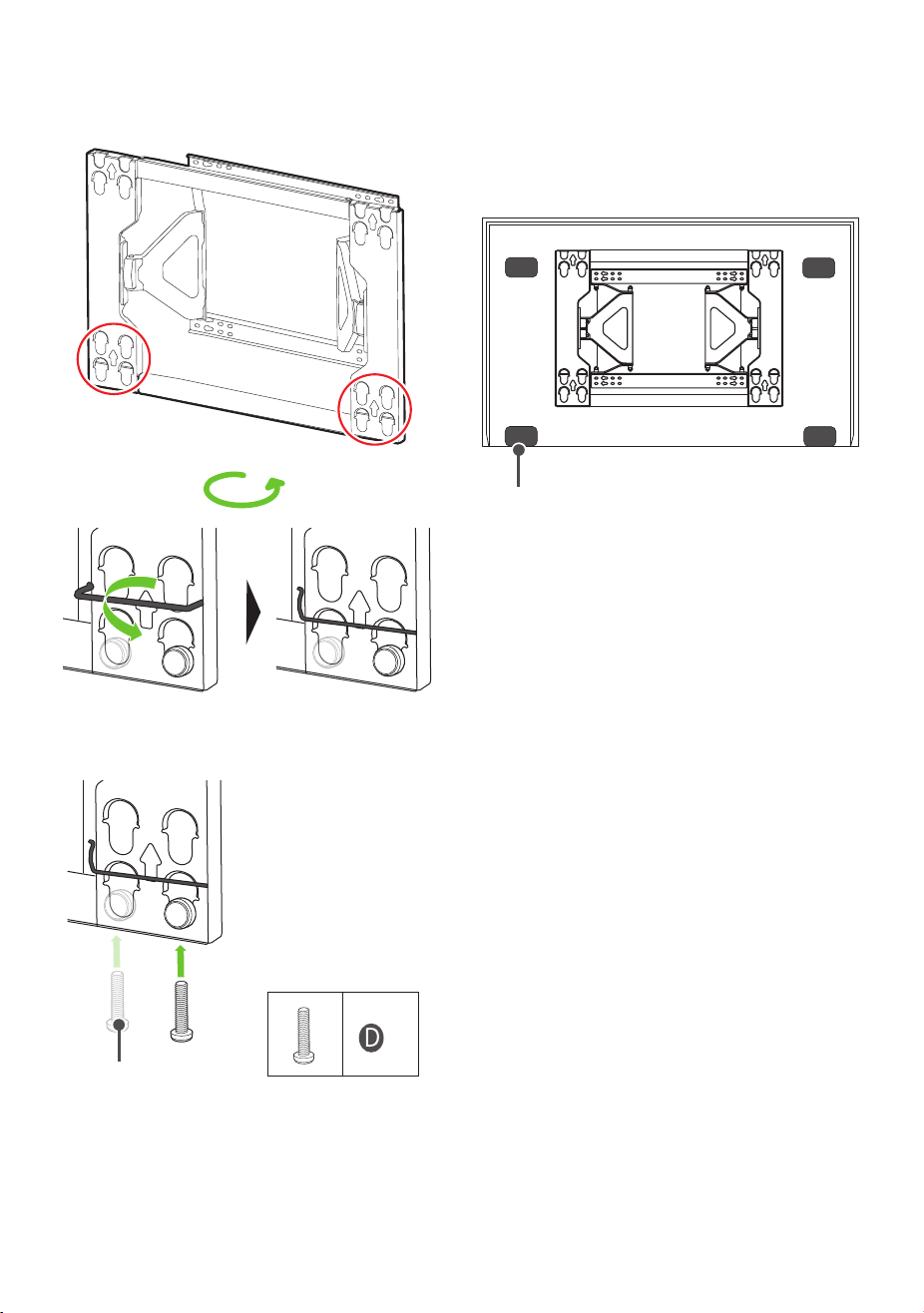
6. Adjusting the level of the product
(tilt)
1. Lower the lock spring.
2. If the product is not level after installation, you can adjust it using the
screws. The product will move up or down depending on the rotation
direction of the screws.
Levelling screws
x 2
7. Organizing the Cables and
Attaching the Set Protection
Cushion
Attach the set protection cushion to reduce the shock received by the set
as it bumps into the wall when tilting. Attach it to the desired location as
shown in the image.
Set Protection Cushion
12
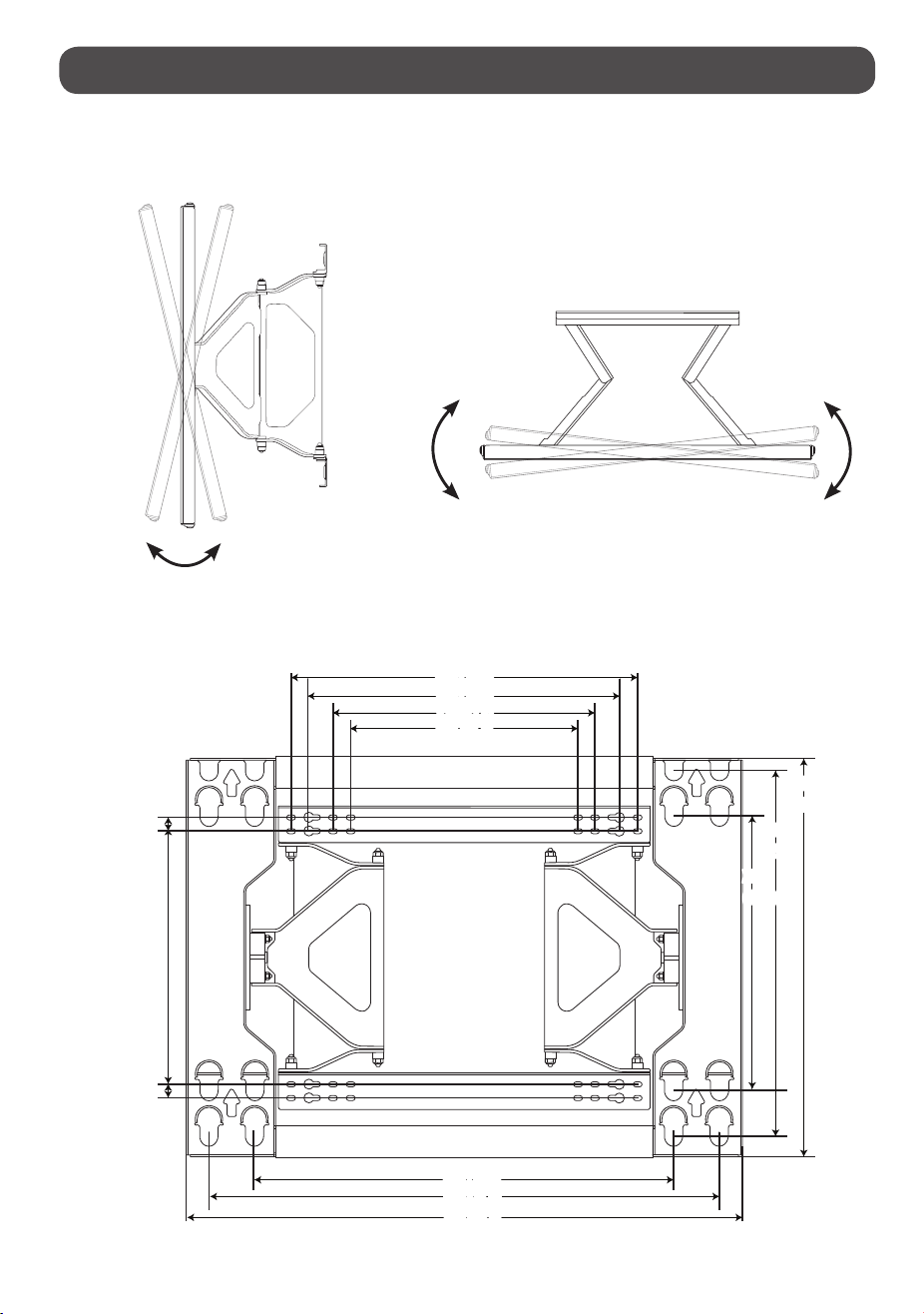
Specications
<With the wall mounting supporter removed.> [Unit: mm(inches)]
12±2°
15° or more
408 (16.0)
440
(17.3)
368 (14.4)
320 (12.5)
280 (11.0)
400
(15.7)
300
(11.8)
500 (19.6)
277 (10.9)
15 (0.5)
15 (0.5)
650 (25.5)
600 (23.6)
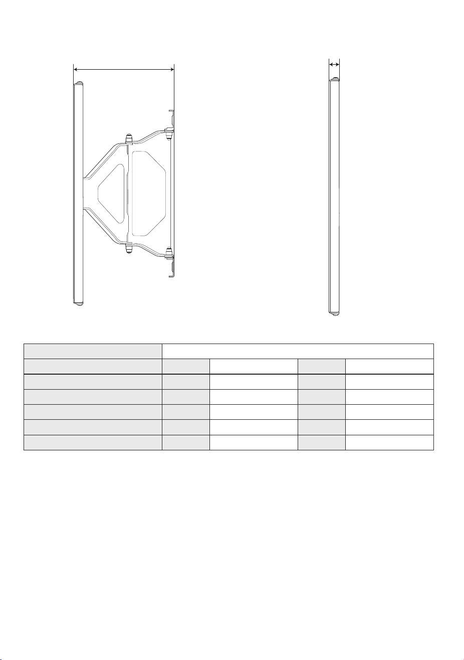
13
[Unit: mm(inches)]
200 (7.8)
19 (0.7)
Model Name WB24GDB
Width mm 650 inches 25.5
Height mm 440 inches 17.3
Depth mm 19 inches 0.7
Product Weight kg 6.0 lbs 13.2
Wall Mount VESA Specications mm 600 x 400, 500 x 400 inches 23.6 x 15.7, 19.6 x 15.7
Max. Tensile Load kg 80 lbs 176.3
14
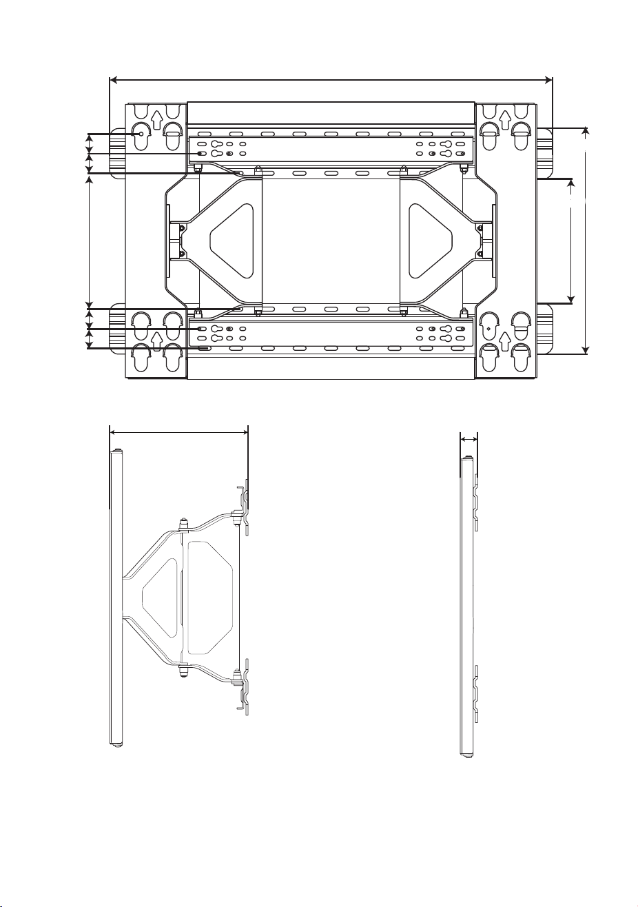
<With the wall mounting supporter attached.> [Unit : mm]
31 (1.2)
31 (1.2)
31 (1.2)
31 (1.2)
214.6 (8.4)
196.6 (7.7)
700 (27.5)
356.6 (14.0)
206 (8.1)
25 (0.9)
15
Model Name WB24GDB
Width mm 700 inches 27.5
Height mm 440 inches 17.3
Depth mm 25 inches 0.9
Product Weight kg 8.5 lbs 18.7
Wall Mount VESA Specications mm 600 x 400, 500 x 400 inches 23.6 x 15.7, 19.6 x 15.7
Max. Tensile Load kg 80 lbs 176.3

16