

2
Table of contents ……………………………………………………………………................. 2
General safety warnings ………………………………………………………………………… 3–4
Eye, ear & lung protection ………………………………………………………………………. 3–4
Electrical safety …………………………………………………………………………………... 4
Power tool safety ……………………………………………………………………................. 5–6
General safety rules ……………………………………………………………………………... 5
Work area ………………………………………………………………….……………………... 5
Electrical safety …………………………………………………………………………………... 5
Personal safety …………………………………………………………………………………... 5–6
Power tool use and care .……………………………………………………………………….. 6
Service ……………………………………………………………………………………………. 6
Specific safety rules ……………………………………………………………………………... 7
Extension cord safety ………………………………………………………….………………… 8
Product specifications ………….………………………………………………………………... 9
Symbols …………………………………………………………………………………………… 10
Know your drill ……………………………………………………………………………………. 11
Assembly and operating ………………………………………………………………………… 12-15
Install auxiliary handle & D handle …………………………………………………………… 12
Forward/reverse switch …………………………………………………………………………. 12
Variable-speed switch and dial……………………………………………………………………… 12
Lock-on switch …………………………………………………………………………………… 13
Installing drill bits ………………………………………………………………………………… 13-14
Removing bits ……………………………………………………………………………………. 14
Drilling …………………………………………………………………………………………….. 14-15
Driving screws ……………………………………………………………………………………. 15
Removing the chuck …………………………………………………………………………….. 15-16
Retightening a loose chuck ……………………………………………………………………... 16
Replacing carbon motor brushes……………………………………………………………… 17
Maintenance ……………………………………………………………………………………… 17
Exploded view ……………………………………………………………………………………. 18
Parts list …………………………………………………………………………………………… 19-20
Warranty ……………………………………………………………………….………………….
2
1
TABLE OF CONTENTS
3
EYE, EAR & LUNG PROTECTION
SAVE THESE INSTRUCTIONS FOR REFERENCE
This instruction manual includes the following:
General Safety Rules
Specific Safety Rules and Symbols
Functional Description
Assembly
Operation
Maintenance
Accessories
WARNING: Use hearing protection, particularly during extended
periods of operation of the tool, or if the operation is noisy.
SAVE THESE INSTRUCTIONS FOR REFERENCE
GENERAL SAFETY WARNINGS
WARNING:
Before using this tool or any of its accessories, read this
manual and follow all Safety Rules and Operating Instructions. The important
precautions, safeguards and instructions appearing in this manual are not
meant to cover all possible situations. It must be understood that common
sense and caution are factors which cannot be built into the product.
ALWAYS WEAR EYE PROTECTION THAT CONFORMS WITH CSA
REQUIREMENTS or ANSI SAFETY STANDARD Z87.1
FLYING DEBRIS can cause permanent eye damage. Prescription
eyeglasses ARE NOT a replacement for proper eye protection.
WARNING:
Non-compliant eyewear can cause serious injury if
broken during the operation of a power tool.
4
EYE, EAR & LUNG PROTECTION – cont’d
ELECTRICAL SAFETY
WEAR A DUST MASK THAT IS DESIGNED TO BE USED WHEN
OPERATING A POWER TOOL IN A DUSTY ENVIRONMENT.
WARNING:
Dust that is created by power sanding, sawing, grinding,
drilling, and other construction activities may contain chemicals that are
known to cause cancer, birth defects, or other genetic abnormalities. These
chemicals include:
Lead from lead-based paints
Crystalline silica from bricks, cement, and other masonry products
Arsenic and chromium from chemically treated lumber
The level of risk from exposure to these chemicals varies, according to how
often this type of work is performed. In order to reduce exposure to these
chemicals, work in a well-ventilated area, and use approved safety
equipment, such as a dust mask that is specifically designed to filter out
microscopic particles.
SAVE THESE INSTRUCTIONS FOR REFERENCE
WARNING:
To avoid electrical hazards, fire hazards or damage to
the tool, use proper circuit protection.
This tool is wired at the factory for 120 Volts AC operation. It must be
connected to a 120 Volts AC, 15 Amps circuit that is protected by a time-
delayed fuse or circuit breaker. To avoid shock or fire, replace power cord
immediately if it is worn, cut or damaged in any way.
GENERAL SAFETY WARNINGS
POWER TOOL SAFETY

5
WARNING: Read all safety warnings and
all instructions. Failure to follow the warnings
and instructions may result in electric shock, fire
and/or serious injury.
Save all warnings and instructions for future
reference.
Work area safety
Keep work area clean and well lit. Cluttered or
dark areas invite accidents.
Do not operate power tools in explosive
atmospheres, such as in the presence of
flammable liquids, gases or dust. Power tools
create sparks which may ignite the dust or
fumes.
Keep children and bystanders away while
operating a power tool. Distractions can cause
you to lose control.
Electrical safety
Power tool plugs must match the outlet.
Never modify the plug in any way. Do not
use any adapter plugs with earthed
(grounded) power tools. Unmodified plugs and
matching outlets will reduce risk of electric
shock.
Avoid body contact with earthed or
grounded surfaces such as pipes, radiators,
ranges and refrigerators. There is an
increased risk of electric shock if your body is
earthed or grounded.
Do not expose power tools to rain or wet
conditions. Water entering a power tool will
increase the risk of electric shock.
Do not abuse the cord. Never use the cord
for carrying, pulling or unplugging the power
tool. Keep cord away from heat, oil, sharp
edges or moving parts. Damaged or
entangled cords increase the risk of electric
shock.
When operating a power tool outdoors, use
an extension cord suitable for outdoor use.
Use of a cord suitable for outdoor use reduces
the risk of electric shock.
If operating a power tool in a damp location
is unavoidable, use a residual current device
(RCD) protected supply. Use of a ground fault
circuit interrupter (GFCI) protected supply. Use
of a ground fault circuit interrupter (GFCI)
reduces the risk of electric shock.
Personal safety
Stay alert, watch what you are doing and use
common sense when operating a power tool.
Do not use a power tool while you are tired
or under the influence of drugs, alcohol, or
medication. A moment of inattention while
operating power tools may result in serious
personal injury.
Use personal protective equipment. Always
wear eye protection. Protective equipment
such as dust mask, non-skid safety shoes, hard
hat, or hearing protection used for appropriate
conditions will reduce personal injuries.
Prevent unintentional starting. Ensure the
switch is in the off-position before
connecting to power source and/or battery
pack, picking up or carrying the tool.
Carrying power tools with your finger on the
switch or energizing power tools that have the
switch on invites accidents.
Remove any adjusting key or wrench before
turning the power tool on. A wrench or a key
left attached to a rotating part of the power tool
may result in personal injury.
Do not overreach. Keep proper footing and
balance at all times. This enables better
control of the power tool in unexpected
situations.
SAVE THESE INSTRUCTIONS FOR REFERENCE
!

6
PERSONAL SAFETY – cont’d
Dress properly. Do not wear loose clothing
or jewelry. Keep your hair, clothing, and
gloves away from moving parts. Loose
clothes, jewelry or long hair can be caught in
moving parts.
If devices are provided for the connection of
dust extraction and collection facilities,
ensure these are connected and properly
used. Use of dust collection can reduce dust-
related hazards.
Power tool use and care
Do not force the power tool. Use the correct
power tool for your application. The correct
power tool will do the job better and safer at the
rate for which it was designed.
Do not use the power tool if the switch does
not turn it on and off. Any power tool that
cannot be controlled with the switch is
dangerous and must be repaired.
Disconnect the plug from the power source
and/or the battery pack from the power tool
before making any adjustments, changing
accessories, or storing power tools. Such
preventive safety measures reduce the risk of
starting the power tool accidentally.
Store idle power tools out of the reach of
children and do not allow persons unfamiliar
with the power tool or these instructions to
operate the power tool. Power tools are
dangerous in the hands of untrained users.
Maintain power tools. Check for
misalignment or binding of moving parts,
breakage of parts and any other condition
that may affect the power tool’s operation. If
damaged, have the power tool repaired
before use. Many accidents are caused by
poorly maintained power tools.
Keep cutting tools sharp and clean. Properly
maintained cutting tools with sharp cutting
edges are less likely to bind and are easier to
control.
Use the power tool, accessories, and tool
bits etc. in accordance with these
instructions, taking into account the working
conditions and the work to be performed.
Use of the power tool for operations different
from those intended could result in a hazardous
situation.
Hold power tools by insulated gripping
surfaces when performing an operation
where cutting tool may contact hidden
wiring or its own cord. Contact with a "live"
wire will make exposed metal parts of the tool
"live" and shock the operator
Service
Have your power tool serviced by a qualified
repair person using only identical
replacement parts. This will ensure that the
safety of the power tool is maintained.
POWER TOOL SAFETY
SAVE THESE INSTRUCTIONS FOR REFERENCE

7
WARNING: Know your drill. Do not plug
the drill into the power source until you have
read and understand this Instruction Manual.
Learn the tool’s applications and limitations,
as well as the specific potential hazards
related to this tool. Following this rule will
reduce the risk of electric shock, fire, or serious
injury.
Always wear eye protection. Any
power tool can throw foreign
objects into your eyes and cause
permanent eye damage.
ALWAYS wear safety goggles (not glasses) that
comply with ANSI safety standard Z87.1.
Everyday glasses have only impact resistant
lenses. They ARE NOT safety glasses.
WARNING: Glasses or goggles not in
compliance with ANSI Z87.1 could cause
serious injury when they break.
WARNING: Always use a safety shield,
hearing protection and dust mask when
drilling concrete.
Do not drill material too small to be securely
held.
Always keep hands out of the path of the drill
bit. Avoid awkward hand positions where a
sudden slip could cause your hand to move into
the path of the drill bit.
Secure the workpiece. Use clamps or a vise to
hold the workpiece. It is safer than using your
hand and it frees both hands to operate the tool.
Make sure there are no nails or foreign objects
in the part of the workpiece to be drilled.
Always remove the plug from the power source
before installing or removing a bit or accessory
from the chuck.
Do not install or use any drill bit that exceeds
7" (17.5 cm) in length or extends more than
6" (15 cm) beyond the chuck jaws. They can
bend or break suddenly.
Always make sure the chuck is tight and the drill
bit firmly tightened in the chuck before starting
drill.
Before starting the operation, jog the drill switch
to make sure the drill bit does not wobble or
vibrate.
Do not use fly cutters or multiple-part hole
cutters, because they can come apart or
become unbalanced during use.
Make sure the spindle has come to a complete
stop before touching the chuck or attempting to
change the drill bit.
SPECIFIC SAFETY RULES
!
!
!
SAVE THESE INSTRUCTIONS FOR REFERENCE

8
WARNING: Keep the extension
cord clear of the working area. Position
the cord so it will not get caught on the
workpiece, tools, or any other obstructions
while you are working with the power tool.
Make sure any extension cord used with
this tool is in good condition. When
using an extension cord, be sure to
use one of heavy enough gauge to
carry the current the tool will draw. An
undersized cord will cause a drop in
line voltage resulting in loss of power
and overheating.
The table at right shows the correct
size to use according to cord length
and nameplate ampere rating. If in
doubt, use the next heavier gauge.
The smaller the gauge number the heavier
the cord.
Be sure your extension cord is properly
wired and in good condition. Always
replace a damaged extension cord or have
it repaired by a qualified electrician before
using it. Protect your extension cord from
sharp objects, excessive heat and damp or
wet areas.
Use a separate electrical circuit for your
power tools. This circuit must not be less
than 14-gauge wire and should be
protected with either a 15 A time delayed
fuse or circuit breaker.
Before connecting the power tool to the
power source, make sure the switch is in
the OFF position and the power source is
the same as indicated on the nameplate.
Running at lower voltage will damage the
motor
MINIMUM GAUGE (AWG)
EXTENSION CORDS (120 V use only)
Amperage
rating
Total length
More
than
Not
more
than
25'
(7.5 m)
50'
(15
m)
100'
(30m)
150'
(45 m)
0 6 18 16 16 14
6 10 18 16 14 12
10 12 16 16 14 12
12 16 14 12 Not Applicable
EXTENSION CORD SAFETY
SAVE THESE INSTRUCTIONS FOR REFERENCE
!

9
P
R
ODUCT SPECIFICATIONS
SAVE THESE INSTRUCTIONS FOR REFERENCE

10
V
Volts
Three-phase alternating current
with neutral
A
Amperes
Read all safety warnings and
instructions
Hz
Hertz
Direct current
W
Watts
No load speed
kW
Kilowatts
Alternating or direct current
Microfarads
Class II construction
L
Litres
Splash-proof construction
kg
Kilograms
Watertight construction
H
Hours
Protective grounding at
grounding terminal, Class I
tools
N/cm
2
Newtons per square
centimetre
Revolutions or reciprocations
per minute
Pa
Pascals
Diameter
OPM
Oscillations per minute
Off position
Min
Minutes
Directional Arrow
S
Seconds
Warning symbol
or a.c.
Alternating current
Wear your safety glasses
Three-phase alternating
current
Wear hearing protection
SYMBOLS
WARNING:
Some of the following symbols may appear on the drill. Study these
symbols and learn their meaning. Proper interpretation of these symbols will allow for
more efficient and safer operation of this tool.
!
SAVE THESE INSTRUCTIONS FOR REFERENCE
This symbol designates that this tool is
listed with Canadian requirements by
ETL Testing Laboratories, Inc.
Conforms to UL Std. 60745-1 and
60745-2-1.
LS106
11
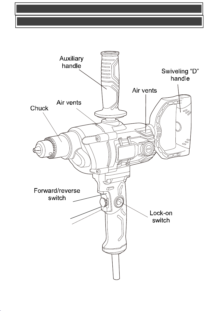
KNOW YOUR
DRILL
ASSEMBLY AND OPERATING
Speed Control Dial
Trigger Switch

12
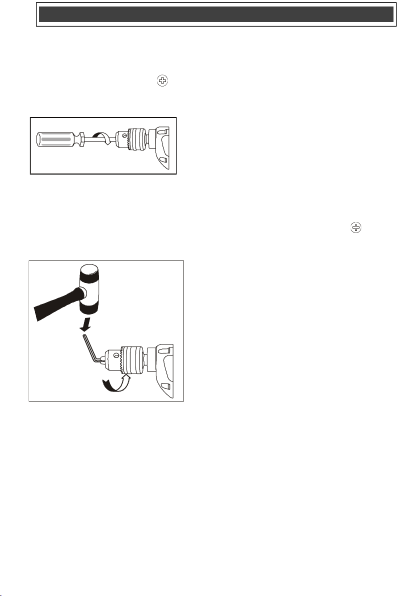
INSTALLING AUXILIARY HANDLE AND
D HANDLE
WARNING: The auxiliary handle and D
handle must be installed as it will provide
additional control over the drill during heavy
drilling operations.
To install the “D” handle (2), insert the “D”
Handle (2) into the hole at the back of the drill
(1), then insert the screw (3), insert the Allen
key (4) into the screw (3), turn it CLOCKWISE to
tighten it. (Fig. 1).
Fig. 1
To install the auxiliary handle (1), simply thread
it CLOCKWISE into the threaded hole (2) in the
top of the drill (Fig. 2).
NOTE: Never use a wrench or pliers to tighten
the assist handle into the drill. Hand tighten
only.
Fig. 2
FORWARD/REVERSE SWITCH
The forward/reverse switch (1) is conveniently
mounted immediately above the trigger switch
on the drill handle (2) (Fig. 3). To make the drill
rotate clockwise for drilling, push the forward/
reverse switch to the left. To make the drill
rotate counter-clockwise, push the
forward/reverse switch to the right.
NOTES:
a) Never change the position of the forward/
reverse switch while the chuck is turning.
b) The trigger switch will NOT function with the
forward/reverse switch in the middle position or
“neutral” position.
Fig. 3
VARIABLE SPEED TRIGGER AND DIAL
This drill is equipped with a variable-speed
ON/OFF trigger switch with speed control dial
1. To start the drill, gently squeeze the trigger
switch (3) (Fig. 4).
NOTE: The drill will turn at its slowest
speed when the trigger switch is depressed
slightly. The drill will turn at its fastest
speed when the trigger switch is fully
depressed.
2. To stop the drill, release the trigger switch.
NOTE: Drilling at a slow speed for an
extended period may cause the
switch to overheat. If the drill gets hot, stop
drilling and allow it to cool for at least 15
minutes.
Fig. 4
SPEED CONTROL DIAL
This feature enables you to pre-set the tool for
a desired RPM when using the “Lock-On”
button feature. The tool speed is adjusted by
rotating the “speed control” dial (4) (Fig. 4)
clockwise to increase the speed and
counterclockwise to decrease the speed. Once
!

13
you have set the speed you desire, when the
switch is completely depressed and the “Lock-
On” button engaged, the tool speed will
change to the speed you dialed in. To Pre-set a
desired RPM, pull the switch back completely
and engage the “Lock-On” button. Maintain a
firm grasp on the running drill with one hand
and use your free hand to rotate the “speed
control” clockwise or counter-clockwise until
the desired drill speed is reached. Then pull
the switch back and release it to disengage the
“Lock-On” feature. Once you’ve dialed in the
desired drill speed, when you start the drill
and engage the switch “Lock-On” button the
drill will change to the speed you set with the
“speed control” dial.
LOCK-ON SWITCH
The lock-on switch is available to hold the
ON/OFF switch in the ON position during
prolonged operation of the drill. To lock the
ON/OFF switch in the ON position:
1.Squeeze the switch trigger (3) (Fig. 5).
2.While squeezing the switch trigger, press
the lock-on button (4) into the drill handle
(2).
3.While holding the lock-on button into the
drill handle release the switch trigger. The
drill will continue to run.
4.To turn the drill OFF while the lock-on
button is holding the trigger switch ON,
squeeze and then release the trigger.
Fig. 5
INSTALLING DRILL BITS
WARNING: Never hold the chuck body
with one hand and use the drill power to
rotate the drill body to loosen or tighten bits.
Serious injury may result.
1. Remove the drill plug from the power
source.
2. Rotate the chuck collar (1) to open or close
the jaws (2) to a point where the opening is
slightly larger than the bit size you intend to
use (Fig. 6).
3.Insert the bit into the chuck the full length
of the jaws. Raise the front of your drill
slightly to prevent the bit from falling out of
the chuck jaws.
4 Insert the chuck key (3) into one of the
three holes in the chuck body. Rotate the
chuck key clockwise until the drill bit is held
firmly in place by the chuck jaws.
NOTE: Do not use a wrench on the chuck
key. You may damage the key or the
chuck.
Fig. 6
WARNING: Do not insert the drill bit into
the chuck and tighten as shown in Fig. 7.
The drill bit MUST be properly inserted with
all three chuck jaws holding the bit centered
in the chuck. Failure to properly insert the
drill bit could cause the drill bit to be thrown
from the chuck resulting in possible serious
injury or damage to the chuck
!
!
ASSEMBLY AND OPERATING

14
INSTALLING DRILL BITS – cont’d
Fig. 7
REMOVING BITS
1. Remove the drill plug from the power
source.
2. Insert the chuck key into one of three holes
in the chuck body. Rotate chuck key
counter- clockwise until the chuck jaws
release the drill bit.
NOTE: Do not use a wrench on the chuck
key or you may damage the key or chuck.
3. Remove the drill bit.
DRILLING
When drilling in smooth hard surfaces such as
metal, use a center punch to mark the desired
hole location. This will prevent the drill bit from
slipping off center as the hole is started.
The workpiece to be drilled should be secured in
a vice or with clamps to keep it from turning as
the drill bit rotates (Fig. 8).
Fig. 8
1. Check the drill bit to make sure it is firmly
locked into the drill chuck and the
forward/reverse switch is in the forward
position.
2. Hold the drill firmly with both hands. Use
your left hand to grasp the main handle
and switch and your right hand to grasp the
auxiliary handle (Fig. 8). If the auxiliary
handle cannot be used due to inadequate
space, use your right hand to grasp the
swivelling “D” handle (Fig. 9).
3. While holding the drill firmly, place the point
of the drill bit at the point to be drilled.
Squeeze the switch trigger to start the drill.
NOTE: Always use a higher drill speed
when drilling small holes. Use a slower drill
speed when drilling large holes.
WARNING
Have you read "GENERAL SAFETY
WARNINGS”, "POWER TOOL SAFETY
WARNINGS", "SPECIFIC SAFETY
RULES", "EXTENSION CORD SAFETY"
and "SYMBOLS" on pages 3, 4, 5, 6, 7, 8
& 9 of this Instruction Manual? If not,
please do it now before you operate this
drill. Your safety depends on it!
Every time you use the drill you should
verify the following:
1. Chuck is tight.
2. Workpiece is properly secured.
3. Safety glasses are being worn.
Failure to adhere to these safety rules
can greatly increase the chances of
injury.
ASSEMBLY AND OPERATING

15
DRILLING – cont’d
4. Move the drill bit into the workpiece
applying only enough pressure to keep the
bit cutting. Do not force the drill bit or apply
sideways pressure to elongate the hole.
Fig. 9
WARNING: Be prepared for binding and
bit breakthrough. When these situations
occur, the drill bit has a tendency to grab the
workpiece. This action will kick the drill
opposite to the direction of the drill bit
rotation and could cause loss of control
when breaking through material as you
complete drilling the hole. If you are not
prepared, this loss of control can result in
possible serious injury.
When drilling metals, use a light oil on the drill
bit to keep it from overheating. The oil will
prolong the life of the drill bit and improve the
drill cutting action. If the bit jams in the
workpiece or if the drill stalls, release the switch
trigger immediately. Remove the bit from the
workpiece and determine the reason for
jamming.
DRIVING SCREWS
When driving screws, care must be taken to use
the bit that correctly fits the screw being driven.
Make sure you use the largest bit size that will
properly fit into the head of the screw.
1. Select the correct screwdriver bit for the
screw being driven.
2. Fasten the screwdriver bit into the chuck,
making sure the flats of the bit are gripped
by the chuck jaws.
NOTES:
a) If the material is particularly soft or porous,
run the drill at slower speeds to avoid over-
driving the screw.
b) Hold the drill firmly with both hands while
driving screws to avoid loss of control.
CHUCK REMOVAL
The drill chuck must be removed in order to use
some accessories. To remove the chuck:
1. Remove the drill plug from the power
source.
2. Insert a 5/16" or larger hex key (1) into the
chuck (2) and tighten the chuck jaws
securely. Make sure each of the three
chuck jaws (3) is seated on the flat
surfaces of the hex key (Fig. 10).
3. Tap the hex key sharply with a mallet (4) in
a CLOCKWISE direction. This action will
loosen the screw in the chuck for easy
removal
Fig.10
!
ASSEMBLY AND OPERATING
16
CHUCK REMOVAL – cont’d
4. Open the chuck jaws and remove the hex
key.
5. Open the chuck jaws as far as possible.
6. Remove the chuck screw using a #2
screwdriver (Fig. 11).
NOTE: Turn screw CLOCKWISE to remove
it. This screw has a left-hand thread.
Fig.11
7. Insert the hex key into the chuck and
tighten the jaws of the chuck securely
(Fig. 12). Tap the hex key sharply with a
mallet in a COUNTER-CLOCKWISE
direction. This will loosen the chuck on the
spindle. The chuck can now be unscrewed
and removed from the spindle by hand.
Fig.12
RETIGHTENING A LOOSE CHUCK
After installing the chuck once it has been
removed, the chuck may become loose on the
spindle and develop a wobble. Also, the chuck
screw may become loose, causing the chuck
jaws to bind and prevent them from closing. To
tighten the chuck, follow these steps:
1. Insert the hex key into the chuck and
tighten the chuck securely.
2. Tap the hex key sharply with a mallet in a
CLOCKWISE direction (Fig. 9). This will
tighten the chuck on the spindle.
3. Open the chuck jaws and remove the hex
key.
4. Tighten the chuck screw using a #2
screwdriver.
NOTE: Turn the screw COUNTER-
CLOCKWISE to tighten it. This screw has a
left hand thread.
MAINTENANCE

17
REPLACING CARBON MOTOR BRUSHES
The carbon motor brushes will wear down and
require replacing. The time intervals between
replacements will vary depending upon the
working environment and the hours of use. It is
recommended that the brushes be checked
after each 10 hours of use. When the length of
the carbon brush reaches 1/4" (6.35 mm), the
brushes should be replaced.
WARNING: Unplug the tool from the
power source.
1. Use a 3/16" (5 mm) slot screwdriver and
remove one brush cap (1) (fig. 13). Turn
the brush cap counter-clockwise to remove
it from the motor housing.
2. Pull the spring & brush assembly (2) from
the brush holder (3) in the motor housing
(4).
3. Insert the new spring & brush assembly
into the motor housing.
4. Compress the spring into the brush holder
and thread the brush cap back into the
motor housing.
NOTE: Make sure the brush cap threads
are not cross-threaded. Do NOT over
tighten.
5. Repeat steps 1 to 4 to replace the second
carbon brush located on the opposite side
of the motor housing.
Fig.13
GENERAL MAINTENANCE
WARNING: When servicing, use only
identical replacement parts. The use of any
other part may create a hazard or cause
product damage.
DO NOT use solvents when cleaning plastic
parts. Plastics are susceptible to damage from
various types of commercial solvents and may
be damaged by their use. Use a clean cloth to
remove dirt, dust, oil, grease etc.
WARNING: Do not allow brake fluids,
gasoline, petroleum-based products,
penetrating oils, etc. to come into contact
with plastic parts. They contain chemicals
that can damage, weaken or destroy plastic.
DO NOT abuse power tools. Abusive practices
can damage the tool and the workpiece.
WARNING: DO NOT attempt to modify
tools or create accessories. Any such
alteration or modification is misuse and
could result in a hazardous condition
leading to possible serious injury. It will also
void the warranty.
LUBRICATION
All of the bearings in this tool are lubricated with
a sufficient amount of high-grade lubricant for
the life of the unit under normal conditions.
Therefore, no further lubrication is required.
!
!
!
!
MAINTENANCE
18
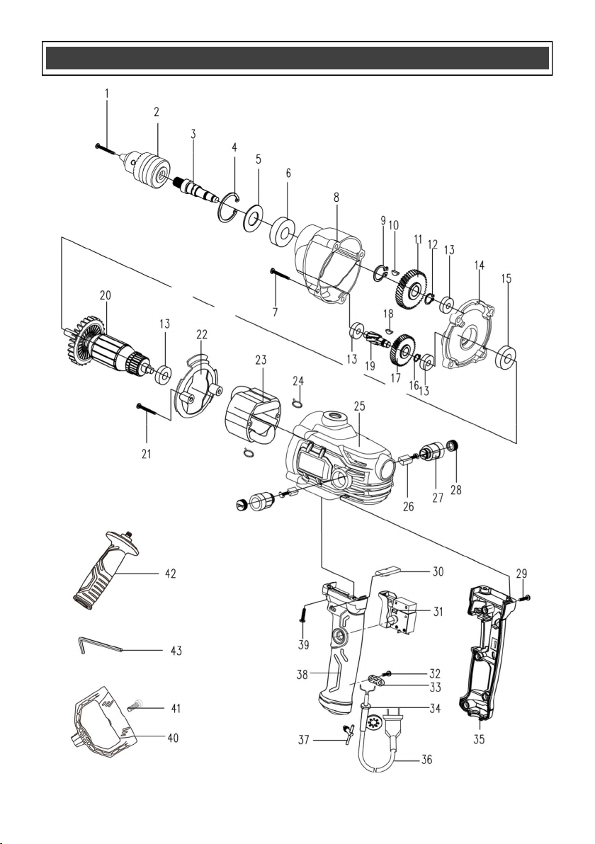
EXPLODED VIEW

19
WARNING: When servicing, use only original equipment replacement parts. The use of any
other parts may create a safety hazard or cause damage to the drill.
Any attempt to repair or replace electrical parts on this saw may create a safety hazard unless repairs
are performed by a qualified technician. For more information, call the Toll-free Helpline, at
1-866-349-8665. Monday to Friday 9-5 EST.
Always order by PART NUMBER, not by key number.
PARTS LIST
!

20
PARTS LIST

21

22
Rev 1.0 5-19-20