
Owner’s Manual
For Use With Residential Sectional Garage Doors Only
www.gdohelp.com
1-877-GDO-4402
1-877-436-4402
● Please read and understand this manual and safety instructions carefully before installation.
● The Opener WILL NOT CLOSE until the Photo Eye Safety System is properly installed and aligned.
● REGULARLY CHECK and TEST the Opener according to the safety label to ENSURE SAFE OPERATION.
● Retain this manual for future reference.
Serial # __ __ __ __ __ __ __ Date Installed __ __ /__ __ /__ __ __ __
GARAGE DOOR OPENER
MODEL: 425-1666
HANDLES DOORS 18 FT. WIDE & UP TO 7FT.TALL
MNOMU08A-4
REV:02-20
Table of Contents
Courtesy light turns on/flashes with audible ‘click’.
(If light bulb is not installed, ‘click’ represents the light)
DO NOT connect power
Please connect power
Introduction
Symbols and Icons 2
Inventory 3
Preparation / Door Balance Test 4
Tools Required 4
Assembly
Rail and Trolley Assembly 5
Installing the Cable and Chain 6
Mounting Header Bracket 7
Installation
Attaching the Opener Assembly to Header Bracket 8
Mounting Door Bracket 8
Mounting Opener to Ceiling 9
Attaching Door Arms 10
Installing Light and Emergency Release Handle 11
Wiring
Wiring Instructions 12
Connecting Photo Eye Safety System 13
Connecting Push Button 14
Connecting Power 15
Adjustment
Aligning the Photo Eye Safety System 15
Travel Limit Adjustment 16
Force Adjustment 17
Final Adjustment and Testing 18
Operation
Programming Hand-held Transmitter - HomeLink® Compatibility 19
Operating the Opener 20-21
Maintenance 22
Troubleshooting 22
Repair Parts and Service
Installation and Accessory Parts 23
Opener Assembly parts 24
Warranty 25
Symbols and Icons
!
WARNING
READ WARNINGS CAREFULLY to prevent SERIOUS INJURY or DEATH caused by
electrocution or mechanical hazard.
2
Installation hardware
3
— Door arms / Mounting Opener
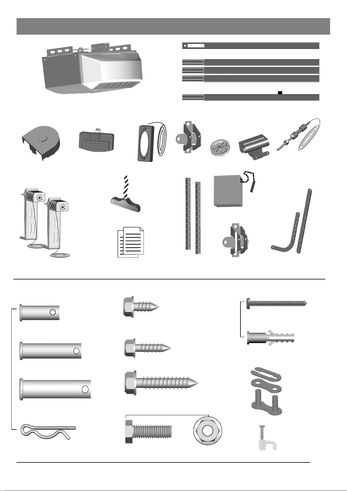
Inventory
x 2
Clevis Pin — Pulley
3/8” x 1-3/4”
Hitch Pin — Locking Clevis Pins
x 5
Lag Screw #12 x 1”— Photo Eye System
Lag Screw 5/16” x 1-1/2”
— Header Bracket / Mounting Opener
Bolt 5/16” x 1” 5/16” Flange Nut
x 4
x 4
x 4
x 4
x 2
x 1
Emergency Release Knob + Rope
Literature + Safety Labels
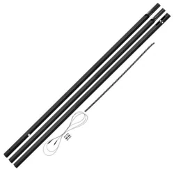
Chain
Photo Eye Safety System
Opener Unit + Lamp Dome
Sprocket Cover
Header
Bracket
Door Bracket
Trolley
Door Arms
Pulley
Rail — Header Segment
Rail — Middle Segments x3
INSTALLATION HARDWARE, LOCATED IN HARDWARE BAG (SHOWN IN ACTUAL SIZE)
Hanging
Brackets
Insulated Staples
— Securing Wires
x 2
Self-Threading Screw 1/4” x 5/8”
Door Bracket
Trolley Shaft
and Cable
Master Link Set
—Trolley Shaft
x 1
Rail — End Segment with Trolley Stop Bolt
Clevis Pin — Door Arms
5/16” x 1”
Clevis Pin — Header Bracket
5/16” x 1-1/2”
Push Button
Handheld
Transmitter
Drywall Anchor - Push Button
x 2
x 2
Screw #6 x1-3/8” - Push Button

Preparation
Level
Tape Measure
Hack Saw
Pencil
Drill, 3/16” and 5/16” Drill Bits
Tools and Additional Parts Required (Sold Separately)
Step Ladder
Screwdriver
Hammer
Sectional Garage Door
BEFORE Beginning Installation:
1. Disable locks and remove all ropes connected to the
garage door.
2. Perform the following door test to ensure your door is
balanced and in good working condition.
To Test Your Garage Door
1. Raise and lower the door to check if there is any sticking or
binding.
2. Check for loose hinges, damaged rollers, frayed cables and
damaged or broken springs.
3. Lift the door approximately halfway and release. The door
should stay at the point under proper spring tension.
Call a qualified garage door service technician if your door binds,
sticks or is unbalanced.
!
WARNING
To prevent SERIOUS INJURY or DEATH:
- Before beginning installation of the Opener please complete the following test to ensure that your door is
balanced and in good working condition.
- A poorly balanced door can cause serious injury and damage to the Opener.
- Always have a qualified garage door service technician make any required adjustments and/or repairs to
your door before proceeding with installation.
- DISABLE ALL LOCKS and REMOVE ALL ROPES connected to the garage door BEFORE installing
and/or operating the Opener.
To prevent damage to the door and Opener:
- DO NOT connect power until instructed.
- Operate this Opener with AC 120V/60Hz grounded power supply ONLY.
Pliers
Adjustable Wrench
4
Ratchet with
5/16”, 7/16” and 1/2” sockets
DO NOT REUSE PARTS FROM ANOTHER BRAND OF OPENER!!!
Angle Iron
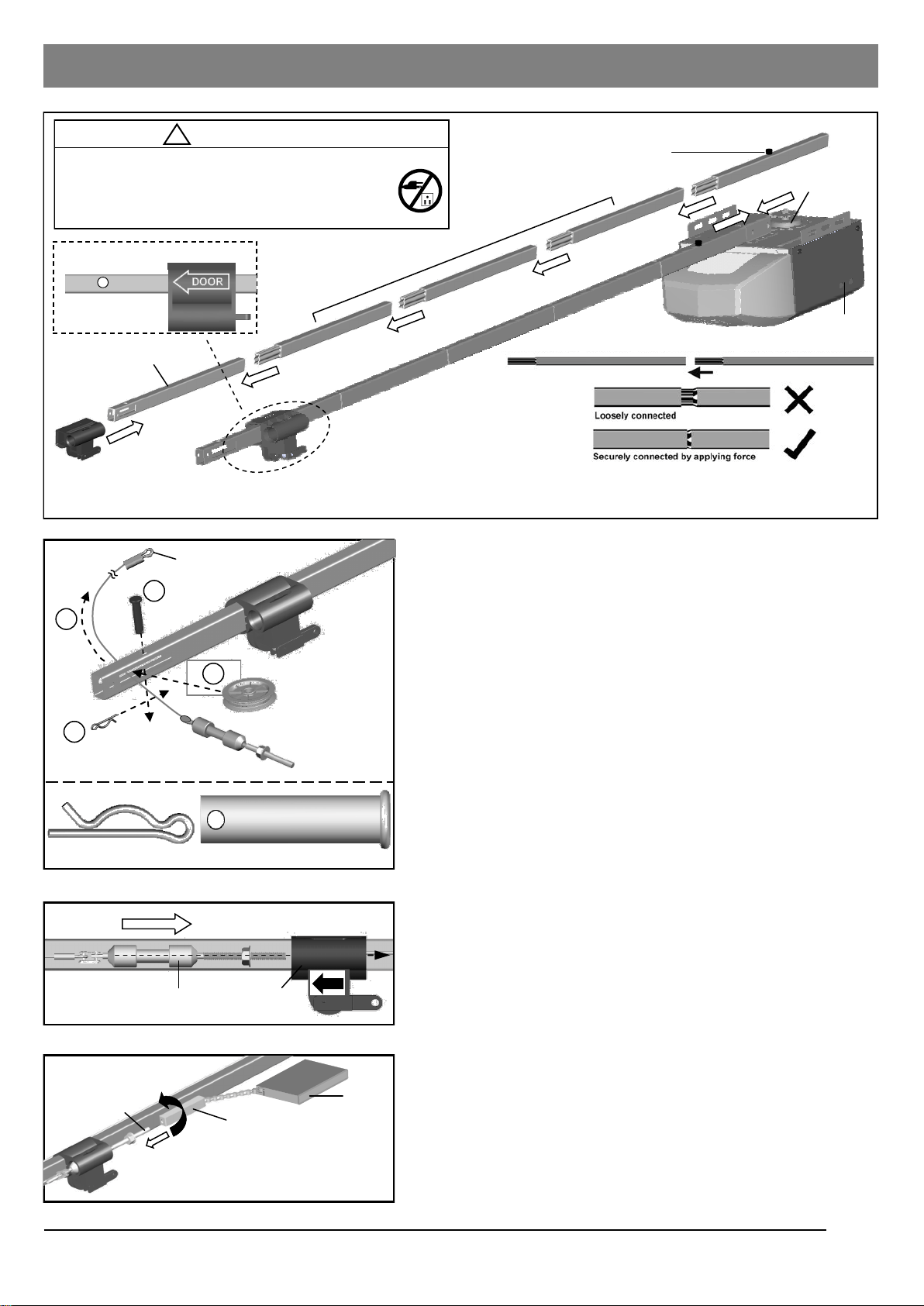
Rail and Trolley Assembly
Opener
Trolley direction (Top Down View)
Clevis Pin
Pulley
Hitch Pin
Clevis Pin — 3/8” x 1-3/4”
Hitch Pin
Connect shaft to Trolley with “click”
To Assemble Rail and Opener
1. Prepare the rails as shown in Fig.1.
2. Connect the rails starting with the Header Segment. Insert
the tapered ends into open ends, apply any additional force
necessary by tapping the Rail with a rubber mallet on
padded flooring. Ensure the End Segment has Trolley Stop
Bolt facing up. Make sure the rails are securely joined
together as shown.
3. Slide the Trolley onto the rail from the Header Segment.
Make sure the arrow is pointing towards the door as shown
in Fig.1.
4. Connect the rail assembly to the Rail Bracket on the
Opener.
To Assemble the Header Section of Rail
Follow steps shown in Fig.2:
1. Remove the “Trolley Shaft and Cable” from the Chain carton
and lay it beside the rail assembly. Hold Cable Eyelet on the
end of cable and thread about 20” (50cm) through the slot
on the Header Segment of the rail.
2. Insert the Pulley into the opening while the cable is hanging.
3. Secure the Pulley by inserting the 3/8” x 1-3/4” Clevis Pin
through the top of the rail.
4. Lock the Clevis Pin with a Hitch Pin. Rotate the Pulley to
ensure it spins smoothly.
Refer to Fig.3 to connect the Trolley Shaft to the Trolley. Slide
both the Trolley Shaft and Trolley towards each other. A “click”
will be heard when they are connected.
To Link Cable with Chain
Refer to Fig.4. Place the chain carton beside the rail, hold the
“Chain to Cable Connector” and pull about 8” (20cm) of chain
from the box. Thread the Chain to Cable Connector onto the
Trolley Shaft so that they are loosely linked together.
Fig.1
Fig.2
Fig.4
Fig.3
!
CAUTION
- DO NOT connect power until instructed.
- To prevent INJURY, keep hands and fingers
away from joints and possible sharp edges.
- Wear gloves when installing chain and cable.
Rail Bracket
1
3
4
2
Trolley Shaft
Trolley Shaft Trolley
Cable Eyelet
Loosely link together
Trolley Shaft
Chain-to-Cable Connector
Chain
5
When connecting the rails ensure they are securely connected as shown above.
To apply additional force tap gently on the end of the rail with a rubber mallet*.
*Only use a soft rubber mallet to tap on the end of the rails as other tools may damage your rail.
Rail — Header Segment
Rail — Middle Segments
(tapered) x 3
Rail — End Segment (tapered)
with Trolley Stop Bolt
DOOR
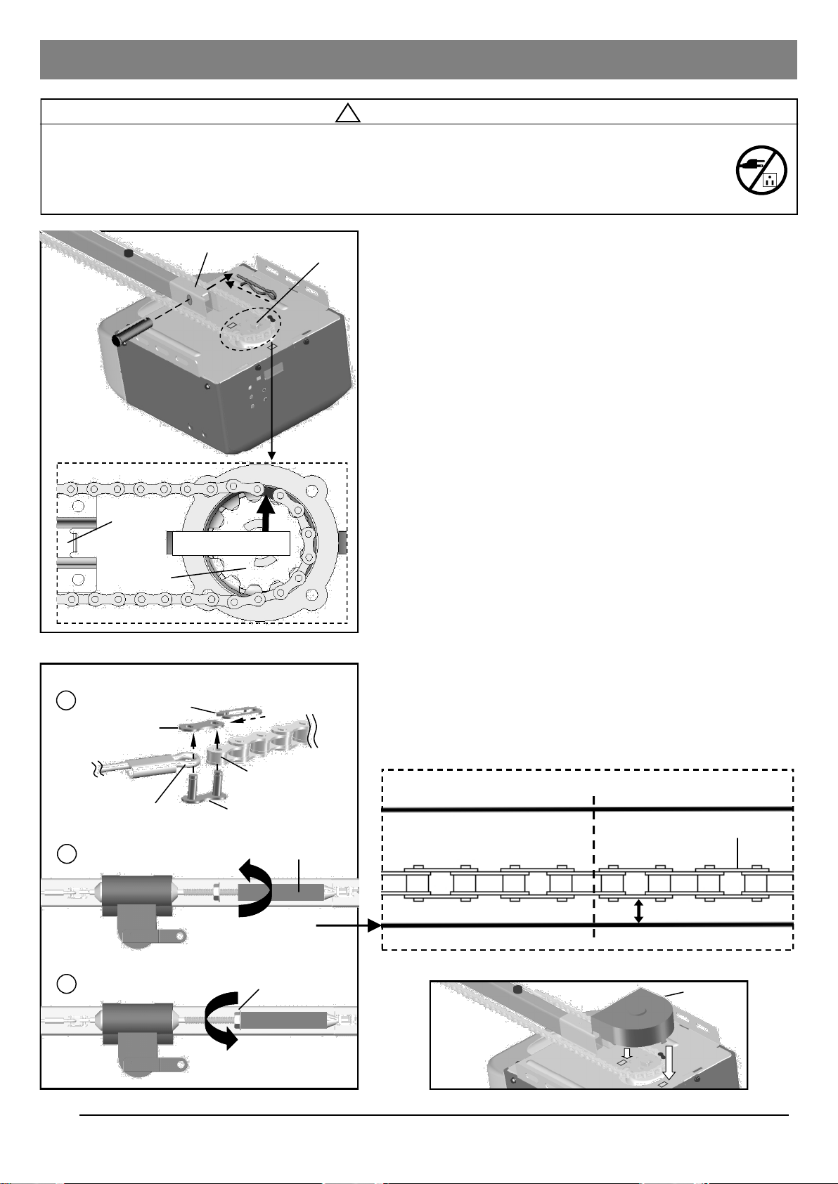
To Install Chain
1. Pull the remaining chain along the rail toward the Opener.
2. A segment of chain marked in RED will be seen. Place this
segment in the approximate location on the sprocket as
shown in Fig.1.
3. When the chain is aligned properly around the sprocket, pull
the Chain-to-Cable Connector towards the Trolley Shaft.
Follow steps shown in Fig.2 to connect & tighten the chain:
1. Align the open end of the chain to the Cable Eyelet and
connect together using the Master Link Set.
2. Turn the Chain-to-Cable Connector on the Trolley Shaft
until the chain is about 1/4” (6mm) above the base of the
rail. Compare with the illustration below.
3. Tighten the Flange Nut on Trolley Shaft against the Chain-to
-Cable Connector.
When the chain and cable are tightened around the rail and
sprocket on the Opener, check and make sure the chain is
properly aligned and not twisted. Attach the Sprocket Cover to
the Opener as shown in Fig.3.
Notice
During operation, it is normal for the chain to appear loose when
the door is closed. If the chain returns to the position as shown
below when the door is opened, the chain is adjusted properly.
DO NOT re-tighten the chain.
When performing maintenance, always PULL the Emergency
Release to DISCONNECT the door from Opener before adjusting
the chain.
Installing Cable and Chain
!
WARNING
To prevent SERIOUS INJURY:
- DO NOT connect power until instructed.
- Keep hands and fingers clear from sprocket during operation.
- Wear gloves when installing chain and cable.
- Keep hands and fingers away from joints and possible sharp edges.
Cable
Chain
Fig.1
Fig.2
Fig.3
Sprocket
Sprocket
Cover
2
Tighten until...
1/4” (6mm)
Base of Rail
Mid-point of rail assembly
3
Tighten nut
Flange Nut
Master Link
Link Cap
Spring Clip
Cable Eyelet
1
Open end of chain
Chain to Cable Connector
To Connect and Tighten the Chain:
Sprocket
Rail Bracket
Rail Bracket
Chain
Top of Rail
6
Chain in RED
Actual Size
Clevis Pin
Hitch Pin
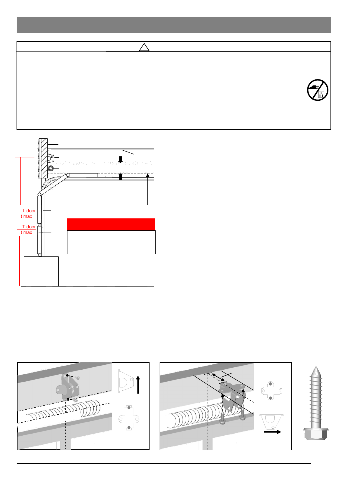
To Install Header Bracket
Note: Installation procedures may vary according to door
type.
1. While inside your garage, close the door and mark the
vertical centerline of the garage door. Extend the line onto
the header wall above the door spring.
2. Open the door to the highest point of travel. Mark a line on
the header wall 2” (5cm) above the highest point of travel.
Note: DO NOT install the Header Bracket over drywall. In some
installations, it may be necessary to install a 2x4 across two wall
studs to create a suitable location for the Header Bracket.
If installing into masonry, use concrete anchors (not provided).
Wall-Mounting
As shown in Fig.2, place the Header Bracket on the vertical
centerline in direction shown.
Mark and drill two 3/16” holes. Fasten the Header Bracket
securely to a structural support using two 5/16” x 1-1/2” Lag
Screws.
Alternative Ceiling-Mounting
Ceiling-Mounting is suggested ONLY when clearance is minimal.
Extend the vertical centerline onto the ceiling as shown in Fig.3.
Center the Header Bracket on the vertical mark, no more than
6” (15cm) from the header wall. Mark and drill holes to fasten the
Header Bracket securely to a structural support.
Mounting Header Bracket
UP
OPENER
MAX. 6” (15cm)
Highest Point of Door Travel
Vertical Centerline
Horizontal Line
Finished Ceiling
Lag Screw
5/16” x 1-1/2”
!
WARNING
To prevent SERIOUS INJURY:
- DO NOT connect power until instructed.
- The Header Bracket MUST be SECURELY fastened to the structural support on the mounting wall or
ceiling, otherwise the door may not reverse when required. DO NOT install the Header Bracket over drywall.
- Concrete anchors MUST be used when mounting the Header Bracket into masonry.
- NEVER try to loosen, move or adjust garage door springs, cables, Pulleys, Brackets, or hardware, all of
which are under EXTREME tension.
- Contact a qualified garage door service technician if your door binds, sticks or is unbalanced. An unbalanced
door might not reverse when required.
Vertical Centerline
Fig.2 (Wall-Mounting) Fig.3 (Ceiling-Mounting)
7
7FT door
8ft max
8FT door
9ft max
Fig.1
Ceiling
Header Bracket
Header Wall
2” (5cm) clearance
Door Track
Door
Highest Point of Door Travel
Support block on floor
Door Spring
* VERY IMPORTANT! *
Max recommended rail height from floor
7ft door = 8ft max height
8ft door = 9ft max height
MAX RAIL HEIGHT
Floor
Attaching Rail to Header Bracket and Mounting Door Bracket
!
CAUTION
To prevent SERIOUS INJURY:
- DO NOT connect power until instructed.
- REINFORCEMENT is recommended for fiberglass, aluminum or lightweight steel garage doors BEFORE
installing the door Bracket. Contact your door manufacturer for reinforcement options.
Fig.1
Fig.2
Fig.3
Carton
Hitch Pin
Self-Threading
Screw - 1/4” x 5/8”
UP
Vertical Centerline of Door
(a) (b) (c)
2-4” (5-10cm)
Top Edge of Door
8
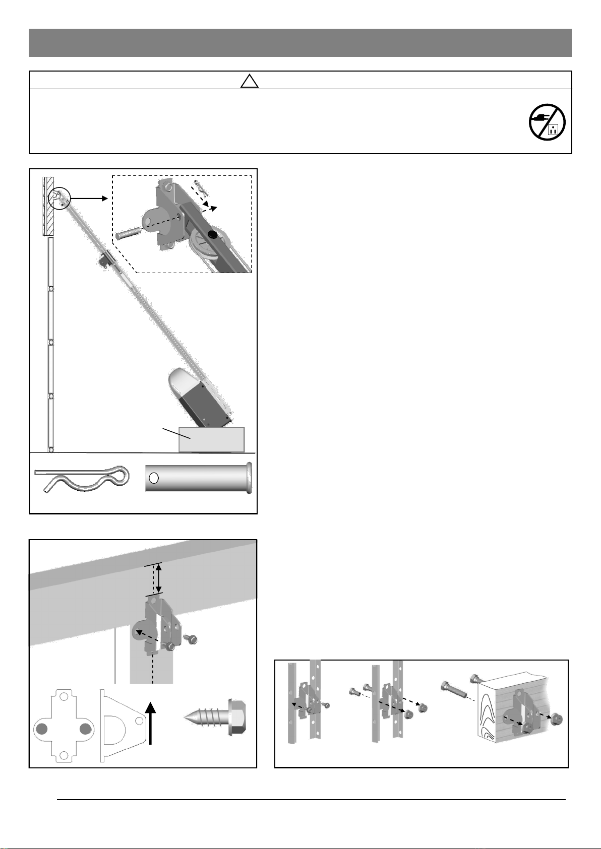
To Attach the Opener to the Header Bracket
1. As shown in Fig.1, use the packaging carton as temporary
support for the Opener. Place the Opener on carton to
prevent damage.
2. Align the mounting hole on the header rail to the mounting
hole on the Header Bracket.
3. Connect the Header Rail and the Door Bracket together
with a 5/16” x 1-1/2” Clevis Pin and lock it in place with a
Hitch Pin.
To mount the Door Bracket
Note: Some door reinforcement kits may provide direct
attachment of the door arm to the reinforcement bracket. If you
have a door reinforcement bracket with this option, skip this step
and proceed with the next step “Mounting Opener to Ceiling”.
1. Position the Door Bracket on the centerline of the door
approximately 2” - 4” (5-10cm) below the top edge of the
door, as shown in Fig.2.
2. Depending on the construction of your door, install using
one of the steps shown if Fig. 3 below:
For steel / lightweight doors with vertical steel
reinforcements / factory reinforced.
(a) Mark and drill two 3/16” holes. Make sure not to drill
through the garage door. Secure the Door Bracket with two
1/4” x 5/8” Self-Threading Screws (provided) as shown in
Fig.3(a).
(b) Alternative installation: Drill two 5/16” holes through the
door. Secure the Door Bracket using two 5/16” Bolts, lock
washers and nuts (not provided) as shown in Fig.3(b). The
length of bolts will depend on the thickness of your door.
Wood door
(c) Mark and drill two 5/16” holes through the garage door.
Secure the Door Bracket using two 5/16” carriage bolts,
washers and nuts (not provided) as shown in Fig.3(c). The
length of bolts will depend on the thickness of your door.
Note: DO NOT use Self-Threading Screws on a wood door.
Clevis Pin - 5/16” x 1-1/2”
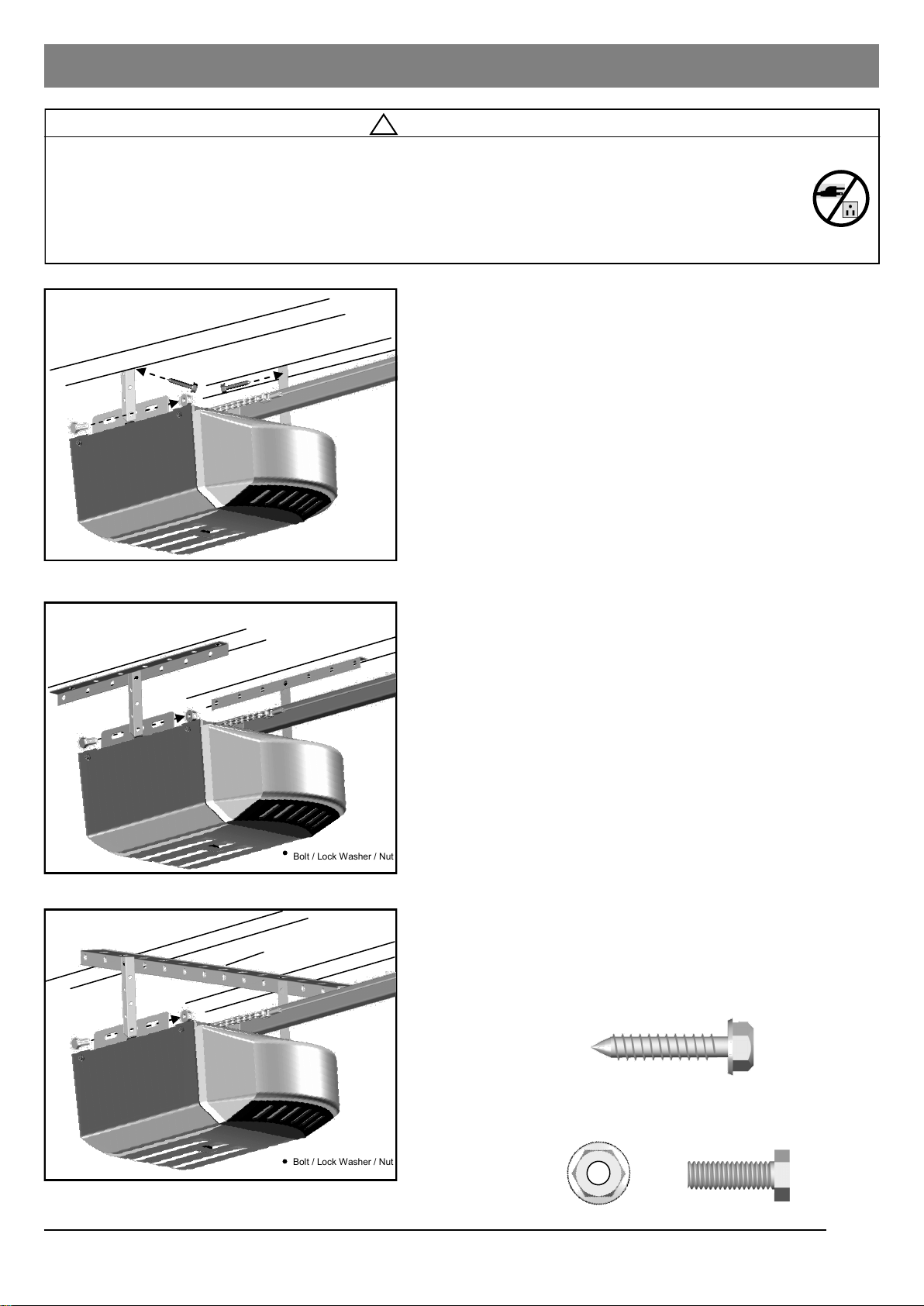
To Mount the Opener to Ceiling
The three most common installation options are shown in
Fig.1-3.
Fig.1 shows mounting the Opener directly to structural
support on the ceiling. Fig.2 and 3 show mounting on a
finished ceiling, with heavy duty angle iron*.
*(angle iron not included)
Determine the mounting option that works best for your
application and follow installation steps below:
1. Raise the Opener and rail assembly and temporarily place it
on a stepladder.
2. Position the Opener and rail assembly so that it is aligned to
the center line of the garage door. If the Header Bracket
was mounted off center, align the Opener with the Header
Bracket.
NOTE: Mounting the Opener off center by more than 8-12”
can cause undue stress on the opener components and the
door itself.
3. Measure the distance from each side of the Opener to the
structural supports.
4. Make sure opener rail is horizontally level and then cut both
Hanging Brackets to appropriate length.
5. Drill 3/16” holes in the structural supports.
6. Secure one end of each of the Hanging Brackets to the
structural supports using 5/16” x 1/2” Lag Screws
(provided).
7. Secure the Opener to the Hanging Brackets and secure
each side with a 5/16” x 1” Bolt and Flange Nut (provided).
8. Move the door manually to check clearance between
highest point of travel of the door and rail. If the door hits the
rail, raise the Header Bracket or adjust the mounting of
Opener.
9. Remove the ladder ONLY when the Opener is securely
Mounting Opener to Ceiling
!
WARNING
To prevent SERIOUS INJURY or DEATH:
- DO NOT connect power until instructed.
- Install the Opener at least 7 feet (2.13m) above the floor.
- Fasten the Opener SECURELY to STRUCTURAL SUPPORTS of the garage to prevent falling.
- If installing Brackets to masonry, concrete anchors (not provided) MUST be used.
Fig.1
Fig.2
Fig.3
Lag Screw 5/16” x 1-1/2”
Bolt 5/16” x 1” Flange Nut
Structural support
Finished ceiling
Finished ceiling
Fastening Hanging Brackets to structural supports
Securing Opener to Hanging Brackets
Bolt / Lock Washer / Nut
not provided
Bolt / Lock Washer / Nut
not provided
Angle Iron not provided
Angle Iron not provided
9
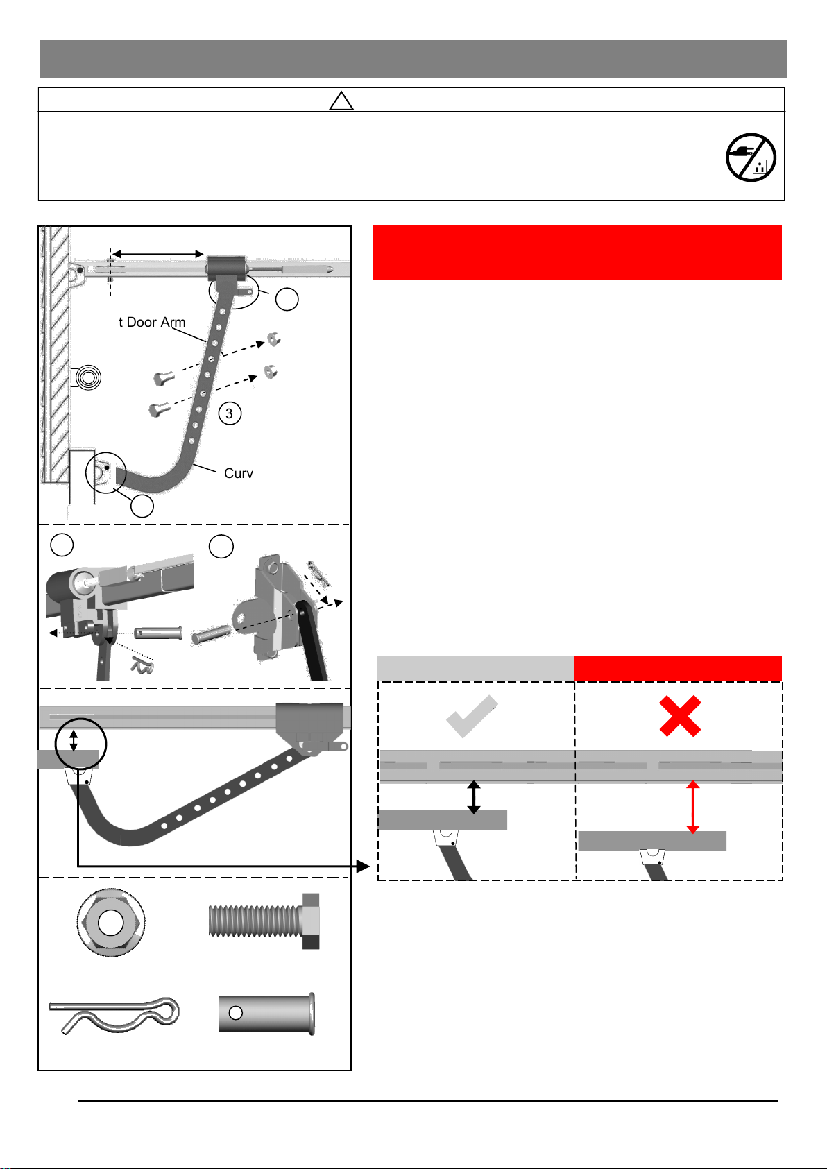
Attaching Door Arms
10
!
WARNING
To prevent SERIOUS INJURY:
- DO NOT connect power until instructed.
- Keep hands and fingers away from the sprocket during operation.
- Wear gloves when installing chain/belt and cable.
- Keep hands and fingers away from joints and possible sharp edges.
Hitch Pin
Bolt - 5/16” x 1”
Flange Nut
Curved Door Arm
Straight Door Arm
1
1
2
2
Fig.1
3
Min. 8” (20cm)
NOTE: The trolley must be a minimum of 8” (20cm) away
from the center of the pulley.
To Connect Door Arm
Follow the steps shown in Fig. 1:
1. Fasten the Straight Door Arm to the Trolley with a
5/16” x 1” Clevis Pin and lock it with a Hitch Pin.
2. Fasten the Curved Door Arm to the Door Bracket with
5/16” x 1”Clevis Pin and lock it with a Hitch Pin.
3. To connect the door arms together, choose two pairs of
holes which are as far apart as possible. Fasten the arms
using two 5/16” x 1” Bolts and Flange Nuts.
2” or less
2” or more
Rail of Opener
Door Panel
Rail of Opener
Door Panel
Correct Spacing
Incorrect Spacing
Clevis Pin - 5/16” x 1”
Installing Light and Emergency Release Knob
!
WARNING
To prevent SERIOUS INJURY or DEATH from electrocution:
- Disconnect power cord before installing/replacing light bulb.
To prevent possible OVERHEATING or damage to Opener:
- Use ONLY A19 (E26) incandescent bulbs* (100W max.).
- DO NOT use short neck or specialty light bulbs.
- DO NOT use halogen bulbs.
* CFL or LED light bulbs will work but may interfere with hand-held transmitters.
6 feet (1.83m) above floor
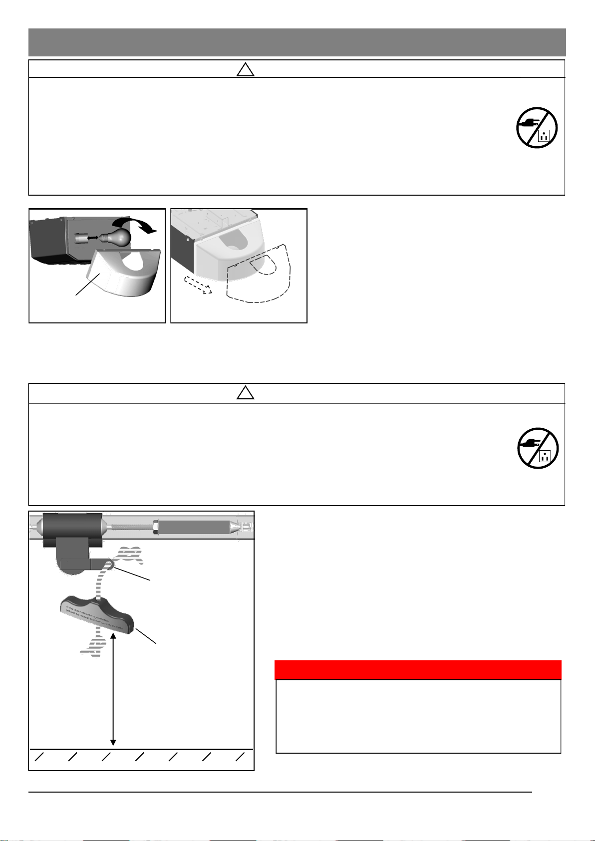
To attach the Emergency Release Knob:
1. Thread one end of the rope through the hole of the
Emergency Release Knob and secure with an overhand
knot.
2. Thread the other end of the rope through the hole in the
Trolley lever.
3. Measure the rope length so that the knob is 6 feet (183cm)
above the floor and is clear from the top of your vehicle.
Secure with a overhand knot.
Fig. 1
Fig. 2
!
WARNING
To prevent SERIOUS INJURY or DEATH from a falling garage door:
- In case of power failure or door obstruction, PULL EMERGENCY HANDLE to release door from Open-
er.
- When Emergency Release is in the released position, the door can be operated manually.
- To reconnect, flip the lever on the Trolley towards Opener, back to Connect position, it will reconnect
automatically upon pressing Push Button or remote control.
- DO NOT use Emergency handle to pull the door open or closed.
Lever
Emergency Release Knob
11
Lamp Dome
* VERY IMPORTANT! *
Emergency Release Knob must clear all vehicles. An
Emergency Release Knob set too low may get caught by
the vehicle and cause damage to the opener. Measure
from the floor to the top of your vehicle and set the
Emergency Release Knob above this measurement.
Fig. 2
To install Light Bulb and Lamp Dome, see Fig. 1:
1. Install a standard A19 (E26) 100 watt maximum
Light Bulb (sold separately).
2. Attach Lamp Dome to the front of the Opener.
To replace Light Bulb and install Light Dome, see
Fig. 2:
1. Pull the Lamp Dome from the top and detach it
from the Opener.
2. Replace Light Bulb (sold separately) and
re-attach the lamp dome.
Notice
When replacing the light bulb, make sure the bulb on
the Opener has cooled down to prevent injury.
Wiring Instructions
12
Photo Eye Safety System
Wires to the terminals on the Opener
Terminals
In the following section, the Photo Eye Safety System and
Push Button will be connected to the Opener. Please read
and understand the wiring instructions before connecting
wires.
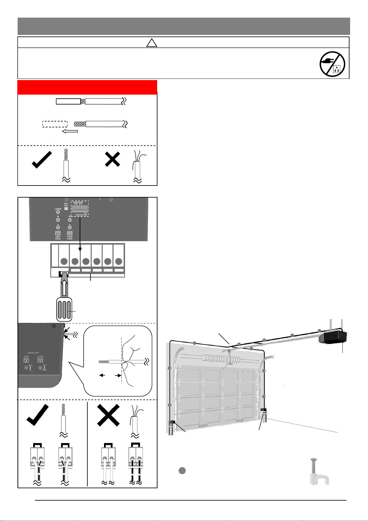
1. Remove the pre-cut skin on the open end of wire from
accessories. Wires MUST NOT be frayed. Wires must be
connected as shown in Fig.1.
2. To connect a wire to an assigned terminal, use a small “flat
head” screwdriver to push in the orange tab on the Wire
Terminal as shown in Fig.2.
3. Insert approximately 1/2” (13mm) of the wire into the
terminal while pushing in the tab as shown in Fig.2.
Release the orange tab to lock wire in place.
4. Each accessory requires a pair of terminals. Each pair of
terminals MUST be connected with one white wire and one
striped wire (non-polarized) from the SAME accessory as
shown in Fig.2.
5. Check for proper connection by gently pulling on the wire.
The wire should not come out of the terminal. NO exposed
part of the wire should be visible outside of the terminal.
6. Use the insulated staples provided to secure the wires to
the wall and/or ceiling. Be careful not to damage the wires
while securing the staples.
!
WARNING
To prevent SERIOUS INJURY or DEATH from electrocution:
- Power MUST NOT be connected until instructed.
- NO exposed part of the wire should be visible outside of the terminal for proper connection.
Suggested placement of insulated staples
Fig. 2
Fig. 1
Wire from accessories
Remove and discard pre-cut skin
Right
Wrong
* VERY IMPORTANT! *
Screwdriver or similar tool
Wire Terminals
Open
Insert into unit Outside
Wire shown in actual size
1/2”
Push In
Connecting Photo Eye Safety System
13
About the Photo Eye Safety System
The Photo Eye Safety System provides protection against
entrapment while the door is closing. When properly connected
and aligned, the Emitter Photo Eye emits an invisible infrared
light beam while the Sensor Photo Eye monitors that beam.
If the beam is obstructed during door-closing, the entrapment
protection will be triggered and the door will stop and reverse to
the open position. The courtesy light will flash for 30 seconds
indicating an obstruction.
Installing The Photo Eye Safety System
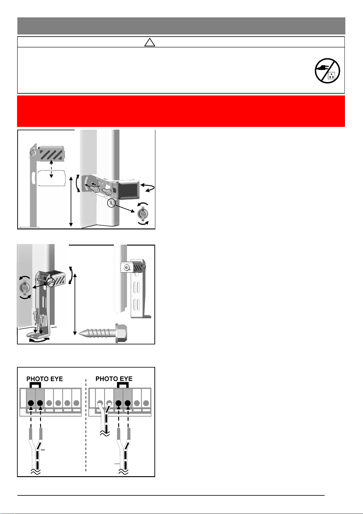
Wall-Mounting
1. Place the Photo Eyes facing each other on each side of
the garage door. Position the sensors so they are no
higher than 6” (15cm) above the floor, as shown in Fig.1.
2. Drill 3/16” holes using the mounting holes on the Bracket
as a template. Secure with #12 x 1” Lag Screws
(provided).
3. Be sure brackets, when mounted, are NOT in contact with
the door track.
4. If necessary use the Optional Wall-mount Position (Fig.1)
to better fit your door-track and improve obstacle
avoidance. To adjust the position, loosen the wing nut,
disassemble the Bracket and move the Photo Eye to the
lower position on the holder.
5. If necessary, align the Photo Eyes by loosening the wing
nut . (This step may be further required in Aligning the
Photo Eye Safety System on page 16.)
Alternative Floor-Mounting
1. Place the Photo Eyes facing each other on each side of
the garage door, as shown in Fig.2.
2. If attaching to concrete, secure the Photo Eyes using
concrete anchors and bolts (not provided).
3. Be sure brackets, when mounted, are NOT in contact with
the door track.
4. If necessary, align the Photo Eyes by loosening the wing
nut. (This step may be further required in Aligning the
Photo Eye Safety System on page 16.)
To Connect Photo Eye Safety System
1. Connect a pair of wires from either one of the Photo Eyes
to a pair of “PHOTO EYE” terminals on the rear of the
Opener as shown in Fig. 3. Refer to Wiring Instructions
on page 13 for proper connections.
2. Repeat step above to connect the other Photo Eye.
3. Refer to Wiring Instructions on page 12 to ensure wires
are connected properly.
!
WARNING
To prevent SERIOUS INJURY or DEATH from electrocution:
- Power MUST NOT be connected BEFORE Photo Eye Safety system is connected and aligned.
- The Opener will not operate until the Photo Eye Safety System is properly connected and aligned.
- Install the Photo Eyes NO higher than 6” (15cm) above the floor.
No part of garage door or other objects should obstruct the Photo Eye Safety System during door-closing.
Fig. 1 (Wall-Mount)
Fig. 3
6” max.
Optional
wall mount
position
Inside
Garage
From one of
the Photo Eye
From the
other one
NOTICE: The opener will not close until the photo eyes are installed. Photo eyes are required by
federal law to be installed on all openers. The opener will not work properly using photo
eyes from another brand of opener and may disable the safety system.
Fig. 2 (Floor-Mount)
#12 x 1”
Lag Screw
Loosen
Inside
Garage
Door Track
Door Track
Inside
Garage
6” max. above floor
Alignment
Alignment
Polarity of photo eye
wire does not matter.
Connecting Push Button
14
!
WARNING
To prevent SERIOUS INJURY or DEATH from electrocution:
- Power MUST NOT be connected until instructed.
To prevent SERIOUS INJURY or DEATH from using the Push Button and a closing door:
- Install the Push Button within sight of the door at a minimum height of 5 feet (1.5m) above the floor.
Make sure it is out of the reach of children and moving parts of door and hardware.
- NEVER permit children to access the Push Button or remote Transmitters.
- Operate the door ONLY when it is adjusted properly with no obstructions present and is in clear sight.
- ALWAYS keep a moving door in sight until it’s completely closed.
- NEVER cross the path of a moving door.
NOTICE: Use Performax brand push button only. Use of other brands of push buttons or buttons
may cause issues or damage to your opener.
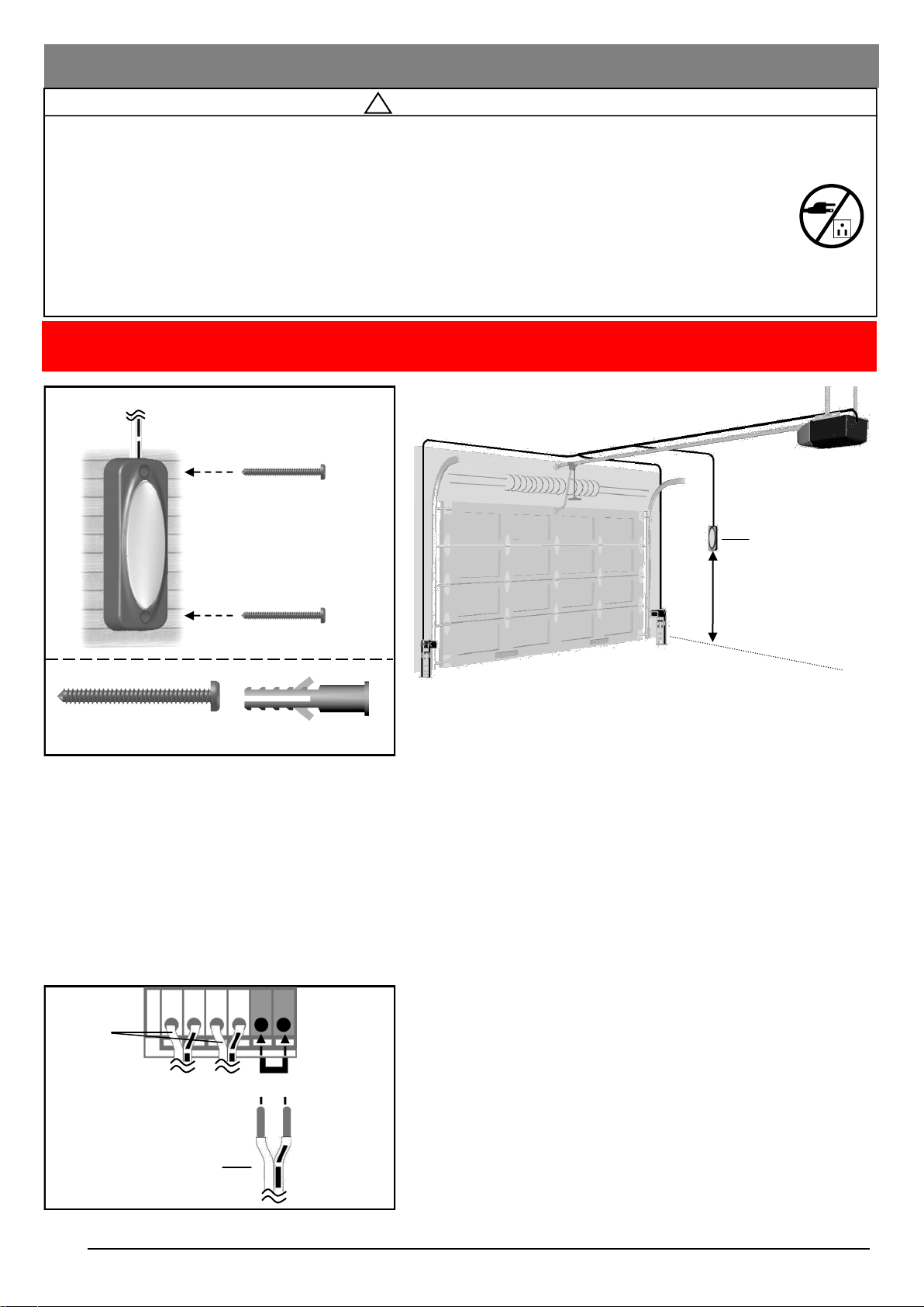
To Connect the Push Button to the Opener
Connect the pair of wires from the Push Button to the pair of
“PUSH BUTTON” terminals on the rear of the Opener. Refer to
Wiring Instructions on page 12 to ensure wires are properly
connected.
The Push Button is a wired, illuminated door control placed
inside your garage.
To install the Push Button:
1. Inside your garage, install the Push Button within sight of
the door at a minimum height of 5 feet (1.5m) off the
ground. Ensure it is installed out of the reach of children
and free from the moving parts of the door and hardware.
2. With the “Bell” icon on the rear cover facing you, securely
fasten it to a solid surface with 1” screws. If attaching to
drywall or other hollow surface, drill 3/16” holes and use
the provided Drywall Anchors.
Push Button
Min. 5 feet (1.5m)
above floor
From Push Button
PUSH BUTTON PHOTO EYES
From
Photo
Eyes
Drywall Anchor
Screw #6 x1-3/8”
Polarity of photo eye
wire does not matter.
Connecting Power
15
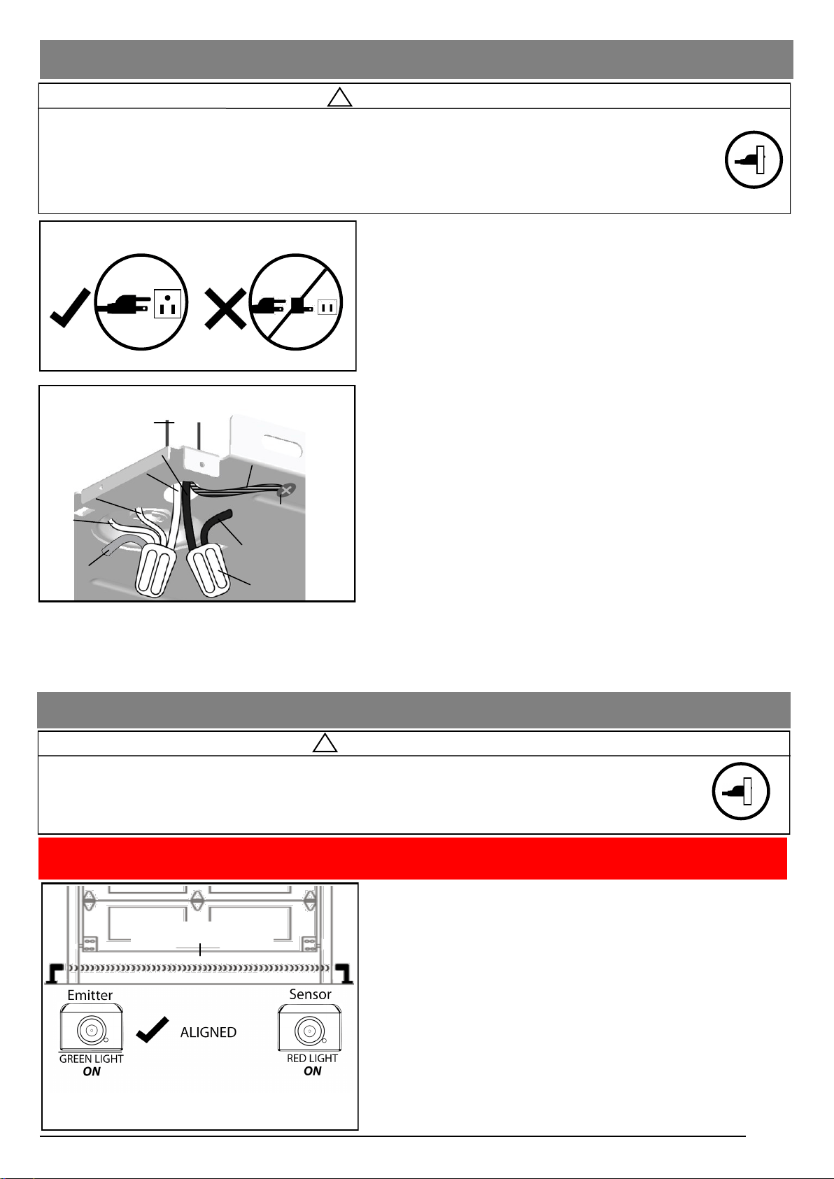
Aligning the Photo Eye Safety System:
1. When power is supplied, the Green photo eye (Emitter) will flash
until it is aligned with the Red photo eye (Sensor). The Red
Photo Eye will not light until it is aligned with the green eye.
2. When the Photo Eye System is properly aligned the Green
Photo Eye (Emitter) will emit a steady green light and the Red
Photo Eye (Sensor) will emit a steady red light.
3. If either of the Photo Eye lights are unsteady, flash or dim, check
for an obstruction and carefully adjust the position of the Photo
Eyes until they give a steady green light and steady red light.
Note: The path of the invisible light beam MUST NOT be
obstructed. No part of the garage door or any hardware
should interfere or block either sensor.
!
Aligning the Photo Eye Safety System
!
WARNING
To prevent SERIOUS INJURY or DEATH from electrocution or fire:
- Power MUST be DISCONNECTED BEFORE proceeding with permanent wiring procedures.
- Garage Door Opener installation and wiring MUST be in compliance with all local electrical and building
codes. Make sure the Opener is ALWAYS grounded.
- NEVER use an extension cord, 2-wire adapter or modify the power plug in any way to make it fit the outlet.
Ordinary Power Connection
WARNING
To prevent SERIOUS INJURY or DEATH from a closing garage door:
- The Photo Eye Safety System MUST be installed BEFORE connecting power.
- The Photo Eye Safety System MUST be properly connected and aligned BEFORE operating the Opener.
NOTICE: The opener will not close until the photo eyes are installed. Photo eyes are required by federal law to
be installed on all openers. Use Performax Brand photo eye only.
Invisible Light Beam
The emitter
generates the
invisible light
beam
The sensor
receives the
invisible light
beam
Steady Red &
Green light
For Permanent Wiring ONLY
Conduit with wire
Yellow (from Motor)
White (from Light)
Neutral (White)
Wire nut (Not provided)
White
(from Logic Board)
Line (Black )
Ground (Green/Yellow)
Black (from Logic Board)
Ground Screw (Green)
DO NOT OPERATE OPENER AT THIS TIME.
To Connect Power
Plug the Opener into a grounded outlet ONLY. If there is no
grounded outlet present, call a qualified electrician to replace the
outlet. Use of a surge protector is highly recommended (page 4).
Permanent Wiring (If Required by Local Code)
1. Remove the enclosure by removing the 6 screws located
on the sides and rear of the Opener.
2. Cut the two cable pressure connectors connecting line
(black) and neutral (white) wire from the power cord.
3. Remove the grounding screw connecting the green wire.
4. Remove the power cord.
5. Group neutral (white) wires from power source with 2 white
wires from light cable, and logic board, and yellow wire
from motor, inside the Opener. Connect them with a wire
nut.
6. Group line (black) wires from power source with another
black wires from logic board inside the Opener. Connect
them with a wire nut.
7. Secure the ground (green or bare) wire from the power
source with a grounding screw.
8. Reinstall the enclosure.
9. Turn on power supply. If the wiring is properly connected, a
“click” should be heard and the light will illuminate (if a bulb
is installed). If there is no response from the Opener, check
power source and wiring.
Travel Limit Adjustment
!
WARNING
To prevent SERIOUS INJURY or DEATH from improper Force Adjustment:
- Improper adjustment of travel limits will cause operation of safety reversal mechanism.
- If Travel limit adjustment is made, Force Adjustment may also be needed.
- After ANY adjustments, the Safety Reverse Test MUST be performed to ensure the door reverses on
contact with a 1-1/2” thick object (2x4* laid flat). *For larger or heavier doors the 2x4 may need to be laid
high side up (3-1/2").
If the door reverses unintentionally
during closing, check below symptoms:
1. The Photo Eye System may be improperly
connected, misaligned or obstructed. The
courtesy light will flash continuously for 30
seconds. Refer to Troubleshooting on P.22.
2. Binding door — Disconnect the door from the
Opener by using the Emergency Release
Handle. Open and close the door manually
and check the following steps.
2.1 If the door is balanced, refer to “Force
Adjustment” to adjust Close force.
2.2 If the door is unbalanced, binding or
jammed, call a trained service person to
adjust the door.
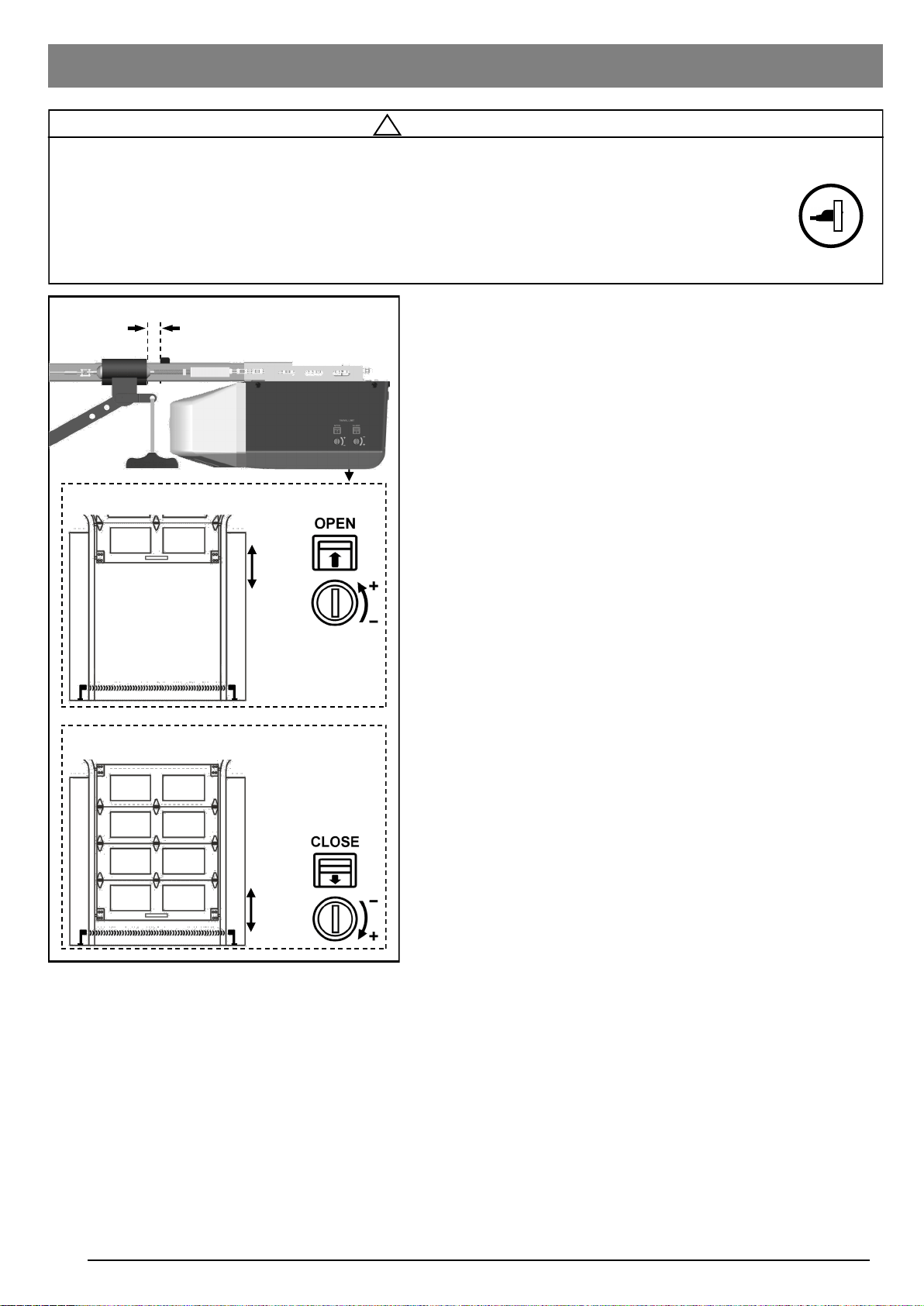
Adjusting Open (Up) Travel Limit
Adjusting Close (Down) Travel Limit
Stop Bolt Trolley
Minimum 2” (5cm) clearance
Open
+
-
Close
-
+
16
About Travel Limits
Limit Adjustments regulate the position at which the door will
stop when opening and closing.
BEFORE making any adjustments, operate the door by using
the push button or Transmitter. Run the Opener through a
complete cycle.
If the door opens and closes completely without unintended
reversing upon closing — NO adjustment is necessary.
If the door does not open or close at desired positions, proceed
with the instructions below to adjust the travel limits.
Adjusting Travel Limits
Open and Close Limits can be increased (+) or decreased (-) by
turning the corresponding screws on the Opener. Use a “flat
head” screwdriver to make adjustments. One full turn of the
screw is about 2” (5cm) of actual travel.
NOTE: The Opener motor includes an automatic thermal
protection system which will shut down the motor in an overheat
situation. The thermal protector will reset itself once the motor
cools down. Opening and closing the Opener multiple times (in
a short period of time) may cause the motor to overheat and
shut down. If this happens, wait about 15 minutes for the motor
to cool and retry operation.
Setting OPEN (UP) Travel Limit
1. CLOSE the garage door by using either the Transmitter or
Push Button.
2. Adjust the OPEN Limit Screw.
3. OPEN garage door and check for proper adjustment.
4. Repeat steps 1-3 until the door opens to the desired
position. When the door is in the open position, make sure
there is enough clearance for your vehicle(s), and there is
a minimum 2“ (5cm) gap between Trolley and Stop Bolt.
5. Perform Safety Reverse Test on page 18.
If the door does not open past 5 feet (1.5m), follow Force
Adjustment on page 17 to adjust the Open Force.
Setting CLOSE (DOWN) Travel Limit
1. OPEN the garage door by using either the Transmitter or
Push Button.
2. Adjust the CLOSE Limit Screw.
3. CLOSE the garage door and check for proper adjustment.
4. Repeat steps 1-3 until door closes to the desired position.
5. Perform Safety Reverse Test on page 18.
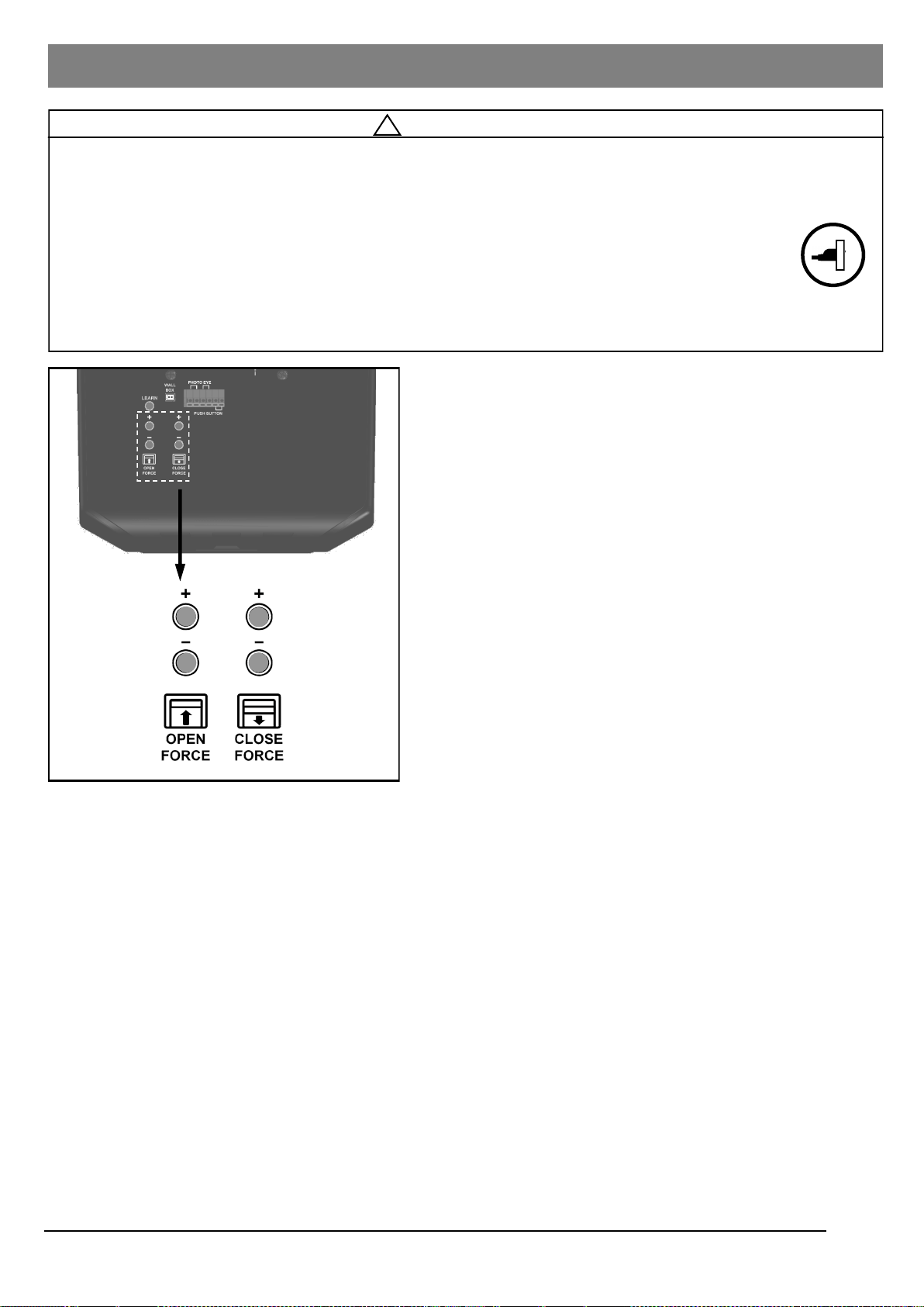
Adjusting Force
1. Force Adjustment controls are located on the rear panel of
the Opener. The force adjustments regulate the amount of
force required to open or close the door.
2. Force Adjustment is applied only to compensate for the minor
resistance caused by weather or other means.
Note: Force is preset at level 6 for both Open and Close
adjustments. The size and operating conditions of the
garage door will determine the correct level of Force/
Sensitivity. Weather conditions may also affect the operation
of the door requiring further adjustments as needed.
Note: If the close force is set too light the Opener will reverse
the door during closing. If the open force is set too light the
Opener will stop the door during opening.
Note: There are 12 levels for open and close force settings.
When either the maximum or minimum level is reached, the
light will flash 6 times.
Never adjust the force setting by more than 1 level (1 press)
at a time.
Setting Force
Setting Close Force
1. If the door completes a full close cycle without reversing,
decrease (-) the Close Force by 1 level at a time until the
door reverses. If the door reverses during closing, increase
(+) Close Force by 1 increment. The Close Force is now
properly adjusted.
2. During the ”door-close” cycle, the Opener will reverse if the
force required to close the door is exceeded.
Setting Open Force
1. If the door completes a full open cycle without stopping,
decrease (-) the amount of force by 1 level until the door
stops during the opening. Once the door stops during
opening, increase (+) Open Force by 1 increment. The Close
Force is now properly adjusted.
2. During the “door-open” cycle the Opener will stop if the force
required to open the door is exceeded.
Force Adjustment
!
WARNING
To prevent SERIOUS INJURY or DEATH from improper Force Adjustment:
- DO NOT adjust force to compensate for binding or sticking of the garage door. Call a qualified garage door service
technician to make necessary adjustments in case of binding.
- DO NOT increase the force beyond minimum force required for closing the door. Too much force will
cause improper operation of safety reversal mechanism.
- If either the Force or Travel limit adjustment is made, the other adjustment may also be needed.
- After ANY adjustments, the Safety Reverse Test MUST be performed to ensure the door reverses on
contact with a 1-1/2” thick object (2x4* laid flat). *For larger or heavier doors the 2x4 may need to be laid high side
up (3-1/2").
For safe operation, the force setting should
always be set at the MINIMUM FORCE
required to run the door.
17
Final Adjustments and Testing
!
WARNING
To prevent SERIOUS INJURY or DEATH from a closing garage door:
- The Safety Reversal Test MUST be conducted ONCE A MONTH.
- NO ONE should cross the path of moving door during operation and/or testing.
- If either Force or Travel limit adjustment is made, the other adjustment may also be needed.
- After ANY adjustments, the Safety Reverse Test MUST be performed to ensure the door reverses on contact
with a 1-1/2” thick object (2x4* laid flat). *For larger or heavier doors the 2x4 may need to be laid high side up (3-1/2").
- The Photo Eye Safety System MUST be properly aligned, and tested regularly.
1-1/2” (3.8cm) thick solid object (or 2x4 laid flat)
30
seconds
18
30
seconds
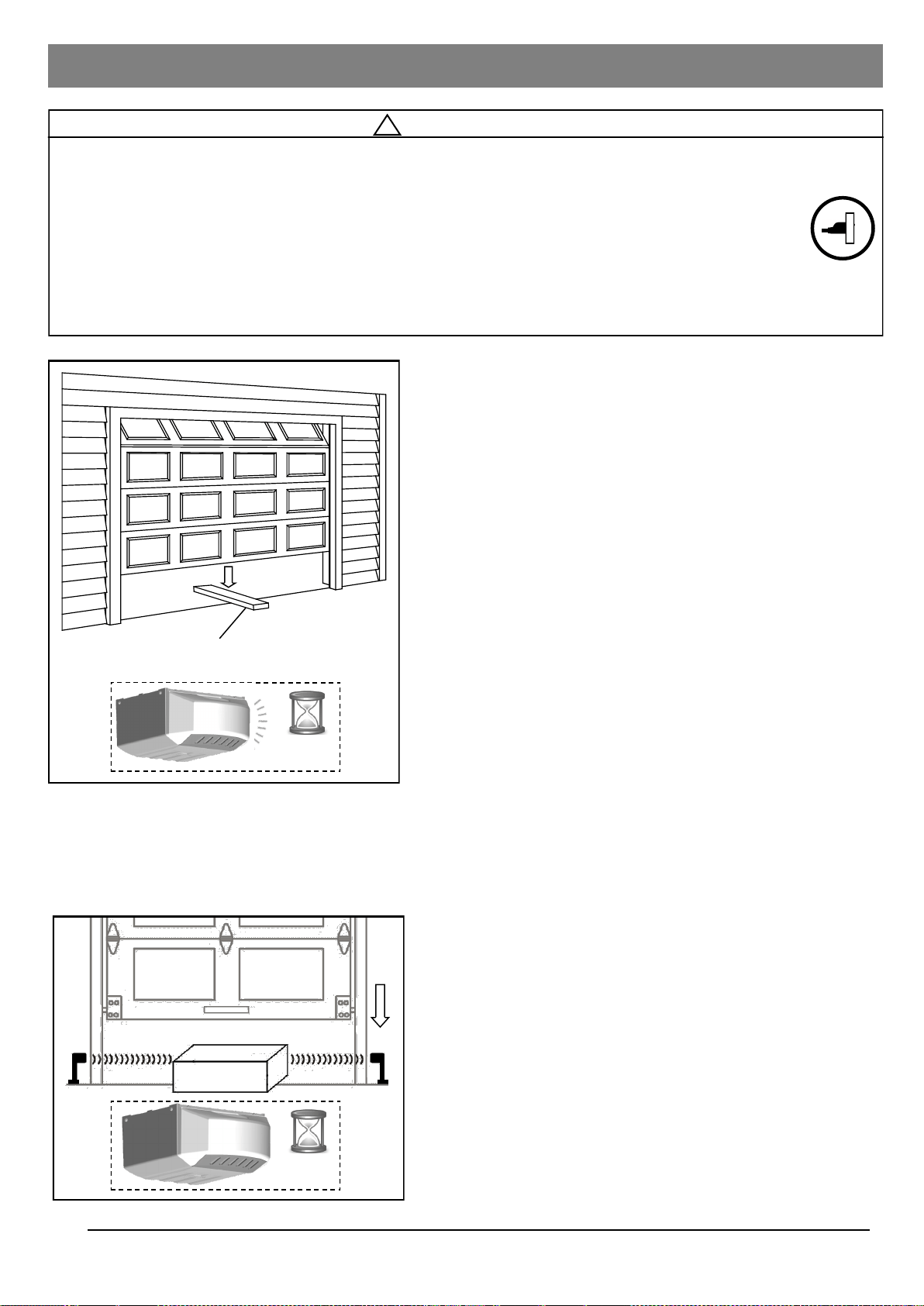
Testing the Safety Reverse System
The Safety Reverse System prevents the door from closing
when an obstruction is present.
1. Open the door by using the Push Button or Transmitter.
2. Place a 1-1/2” (3.8cm) thick solid object (or 2x4* laid flat) on
floor under the center of garage door. *For larger or heavier
doors the 2x4 may need to be laid high side up (3-1/2").
3. Keeping the door in sight, use the Push Button or
Transmitter to close the door.
4. The door MUST REVERSE upon striking the object within
1.5 seconds, and stop at the fully opened position.
5. The courtesy light will start flashing for 30 seconds upon
triggering the Safety Reverse System.
If the door just stops on the object, adjust the Opener as
follows:
The close travel maybe inadequate, Increase Close travel limit
by 1/4 turn (See Limit Adjustment on page 16).
Conduct the test again. If the door reverses on contact, remove
the object and run at least 3 COMPLETE travel cycles to ensure
proper adjustment.
If the door still does not reverse on the object, decrease the
Close Force (see Force Adjustment on page 17) and repeat
the test.
If the Opener still fails the Safety reverse Test, call a qualified
technician for door adjustment.
Testing the Photo Eye Safety System
1. Open the door by using the Push Button or Transmitter
2. Make sure both Photo Eyes steadily emit the green and red
indicator lights. (If not, check alignment)
3. Place an object under the door about 8” (20cm) high by
12” (30cm) wide (the Opener carton can be used).
4. The red indicator light on the sensor eye should be dimmed.
5. Keep the door in sight and use the Push Button or
Transmitter to try to close the door.
6. The door should NOT move more than 1” (2.5cm) and the
courtesy light should flash for 30 seconds.
Programming Hand-held Transmitter
!
WARNING
To Prevent SERIOUS INJURY or DEATH:
- Keep Transmitter and battery out of reach of children.
- NEVER permit children to access the Push Button nor remote Transmitters.
- Operate the door ONLY when it is properly adjusted, and there are no obstructions present.
- ALWAYS keep a moving door in sight until completely closed. NEVER cross the path of a moving door.
To reduce risk of fire, explosion or electric shock:
- DO NOT short circuit, recharge, dissemble or heat the battery.
- Replace with 23AE 12 Volt batteries ONLY. Dispose of batteries properly.
19
Fig.1
Fig.3
Visor Clip
+
-
Fig.2
LEARN
1
2
23AE 12 Volt
Alkaline Battery
3
This device complies FCC Rules for HOME OR OFFICE USE. Operation is subject to the following two conditions: (1) this device may not cause
harmful interference, and (2) this device must accept any interference received, including interference that may cause undesired operation.
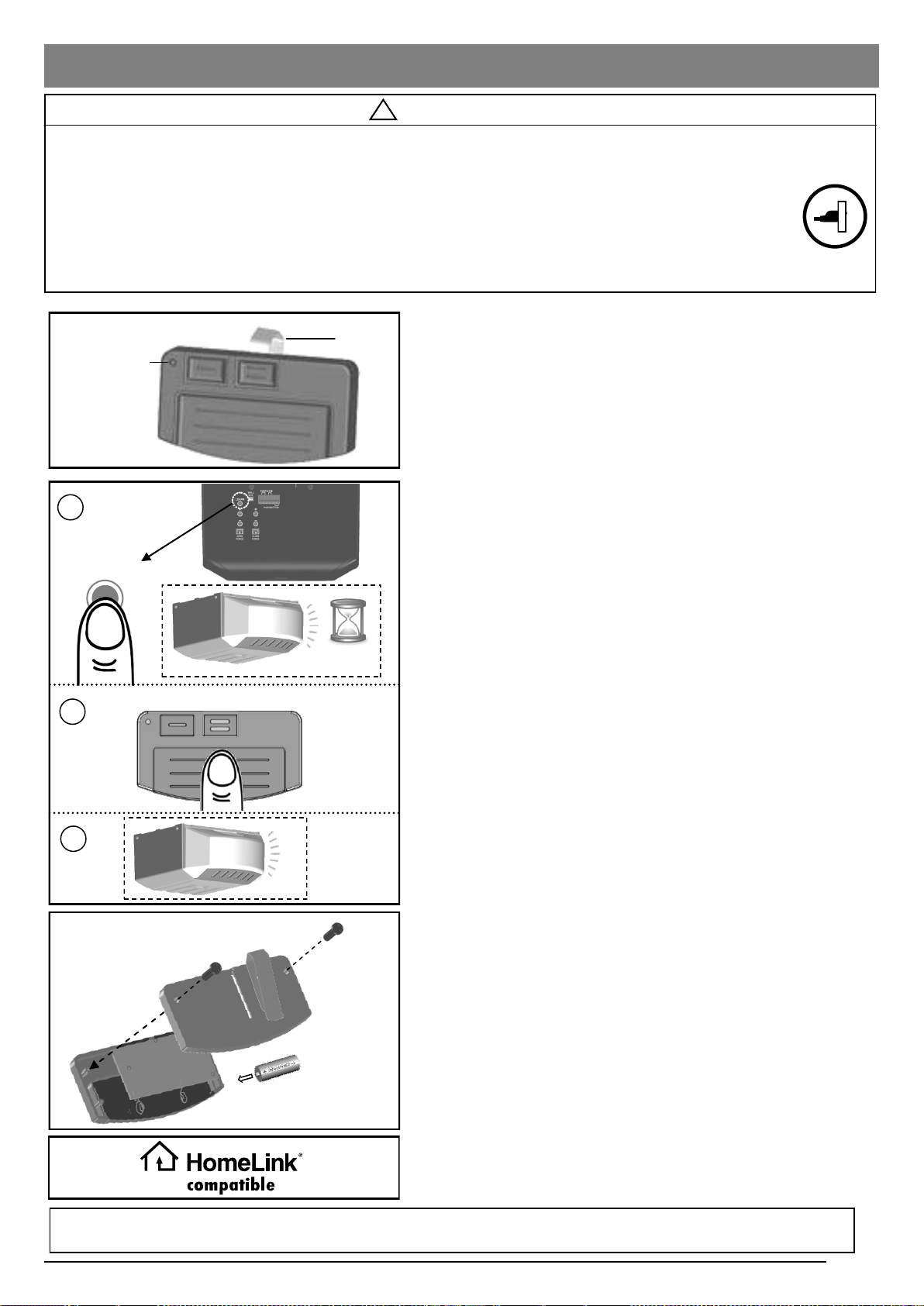
HomeLink® Compatible
This opener is compatible with HomeLink® in-vehicle systems.
Consult your vehicles owner’s manual for correct programming
instructions. NOTE: For all other in-vehicle remote systems, contact the
vehicle manufacturer for correct programming instructions.
To Program Transmitter(s):
1. Press/release the “LEARN” button on the rear control panel of
the Opener. The courtesy light will illuminate with an audible
click*. The unit is now ready to accept a transmitter in the
next 30 seconds as shown in Fig.1.
2. Press/release the large grey button on the Transmitter.
(2 additional buttons at the top of the remote can be
programmed to open other Performax openers. Press learn
button once, then press additional button at the top of the
remote to complete programming for another opener.)
3. The courtesy light will flash twice indicating Transmitter has
been stored successfully**.
Up to 20 Transmitters (including wireless keypad codes) can be
added to the unit by repeating the above procedures.
If more than 20 Transmitters are stored, the first stored
Transmitter will be replaced. (i.e. the 21st Transmitter replaces the
1st stored Transmitter.)
* If the courtesy light is already on, it will flash once and stay
illuminated for 30 seconds.
** If a Transmitter is not accepted, the courtesy light will stay on for
30 seconds, flash 4 times and then stay on for 2-1/2
minutes. Retry programming the Transmitter by repeating the steps
above.
Removing ALL Transmitters:
To remove ALL Transmitters from memory, press and hold the
“LEARN” button for 5 seconds. The courtesy light will flash 7 times
indicating ALL Transmitters have been removed from memory.
x2
Signal and Battery
Indicator
30
seconds
Replacing Transmitter Battery:
When the battery of the hand held Transmitter is low, the
indicator light will become dim and/or the range of the
Transmitter will decrease. To replace the battery, remove the
battery cover from the Transmitter as shown in Fig 3. Replace
with a 23AE 12 volt alkaline battery with polarity shown in Fig.3.
Operating the Opener
!
WARNING
To Prevent SERIOUS INJURY or DEATH:
- READ AND FOLLOW ALL INSTRUCTIONS AND WARNINGS IN THE OWNER’S MANUAL AND LABELS
- Keep Transmitter and battery out of reach of children.
- NEVER permit children to access the Push Button or remote transmitters.
- Operate the door ONLY when it is properly adjusted, and there are no obstructions and is in clear sight.
- ALWAYS keep a moving door in sight until completely closed. NEVER cross the path of a moving door.
- If Travel limit adjustment is made, Force Adjustment may also be needed.
- After ANY adjustments, the Safety Reverse Test MUST be performed to ensure the door reverses on contact with a 1-
1/2” thick object (2x4* laid flat). *For larger or heavier doors the 2x4 may need to be laid high side up (3-1/2").
- ALWAYS ensure that your door is balanced and in good working condition.
20
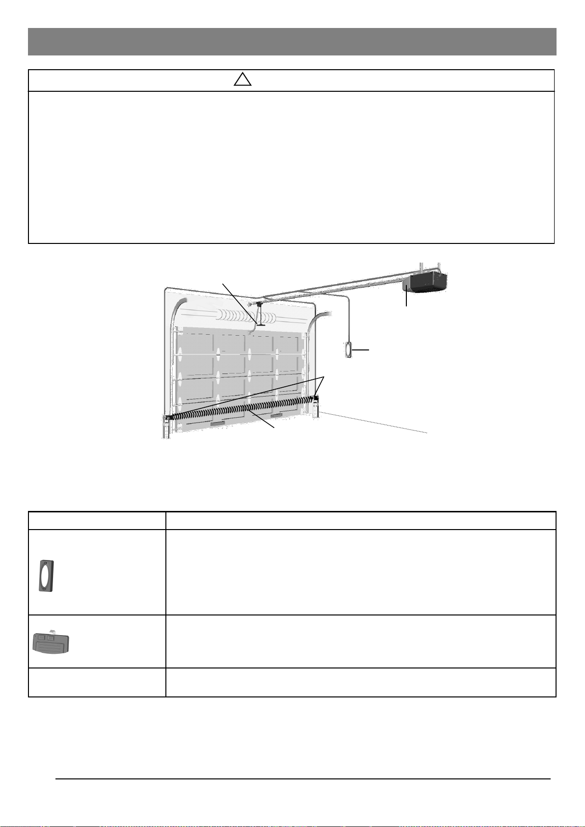
Emergency Release Knob
Photo Eye Safety System
Invisible Light Beam
Push Button
Courtesy Light
Actual Operating Scenario
Controls Operation
Push Button (Indoor)
Press and release the Push Button, the door starts to move, and controls as follows:
- Open or close the door.
- Reverse the door while it is closing.
- Stops the door while it is opening.
Press and hold the Push Button (Not Recommended)
- Close the door when the Photo Eye Safety System is not installed, misaligned or
obstructed INTENTIONALLY.
Hand-Held
Transmitter
Same functions* as the Push Button with remote distance up to 100ft. in open field.
*For safety concerns, the Hand-Held Transmitter WON’T work if the Photo Eye Safety
System is not properly installed and aligned.
Keyless Entry
(Sold Separately)
Program the Keyless Entry pad accordingly and access the door using the PIN code.
Activating the Opener
!
WARNING
To Prevent SERIOUS INJURY or DEATH:
- Use Emergency Release to disconnect Trolley ONLY when the door is CLOSED to prevent unexpected rapid falling in
case of a unbalanced / poor-conditioned door.
- Use Emergency Release ONLY when doorway is clear of persons and obstructions.
- DO NOT use Emergency Release to pull the door open or closed.
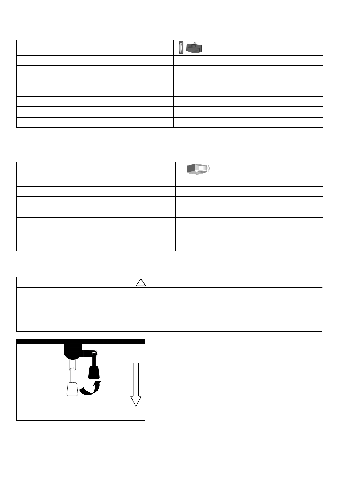
In case of a power failure or door obstruction, PULL
EMERGENCY Knob to release door from Opener.
To Disconnect Trolley for Manual Operation
With the door closed, pull down the emergency release knob to
the DISCONNECT position. The door can be raised / lowered
manually.
To Re-connect Trolley
Pull the knob toward the Opener so that the lever will flip up to
the CONNECT position. The Trolley will reconnect itself when
the Opener is activated or when the door is manually opened/
closed.
Lever
CONNECT
DISCONNECT
Pull to Disconnect
Flip to reconnect
Operation / Condition Courtesy Light Response
Opener is initially plugged-in / Power restored Flashes five times
Upon Opener activation Turns on for 3-1/2 minutes and turns off automatically
“LEARN” button is pressed Turns on for 30 seconds
Remote Transmitter / Keyless Entry PIN code accepted Flashes / Clicks twice
The Photo Eye System is obstructed during door-closing or
door is obstructed during opening
Flashes / Clicks for 30 seconds (Re-align and clear ob-
struction)
Opener motor overheat (Thermal Protection)
Flashes / Clicks 5 times (Wait about 15 minutes to cool
down)
Courtesy Light Responses
Manual Operation
Door status Activation using Push Button / transmitter
Door at fully open / close position Door will move to fully close / open position
Door is closing Door will reverse
Door is opening Door will stop
Door is stopped as intended in partially open position Close
Door is obstructed while closing Door will reverse while flashing courtesy light
Door is obstructed while opening Door will stop
Door is fully opened and Photo Eye System is obstructed Door will not close
Door Status vs. Activation
21

Troubleshooting
Problem Possible Cause / Solution
Opener does not close and light flashes
The Photo Eye may be obstructed, not properly aligned or installed,
check connection and alignment referring to pages 13 & 15.
Opener does not respond to Transmitter
- Refer page 19 to reprogram Transmitter.
- Check Transmitter battery.
Opener stops before reaching full open / close
position
Either the Travel Limit or Force is not properly adjusted, check
adjustment referring to pages 16-17. Conduct Safety Reverse Test
after ANY adjustment.
The door reverses unintentionally
Make sure the Photo Eye Safety System is aligned and clear of
obstructions.
- Refer to page 4 to check the door balance.
- Refer to page 17 to re-adjust the force.
The door reverses upon touching the floor and
the courtesy light flashes
Refer to page 16 to decrease Close Limit by 1/4 turn until door stops
as intended at the fully closed position. Conduct Safety Reverse Test
after ANY adjustment.
The courtesy light flashes 5 times and the
Opener does not start
Opener motor overheat, please wait about 15 minutes and retry.
The Opener does not close the door and the
indicator on one of the Photo Eyes flashes
The Photo Eye Safety System is misaligned or obstructed, refer to
page14 for proper alignment.
The Opener is working properly but the courtesy
light does not turn on
Replace light bulb (A19 incandescent Max.100W).
The courtesy light does not turn off Defective Logic Board.
The Opener hums as the Trolley hits the Trolley
Stop Bolt in open travel
1. Make sure the Trolley is towards the Trolley Stop Bolt.
2. Disconnect the Trolley by using the Emergency Release.
3. Close the door manually.
4. Relieve the chain tension by loosening both the Chain-to-Cable
Connector and the Flange Nut (see page 6).
5. Operate the Opener so the Trolley Shaft travels towards the door
(Trolley should be kept disconnected).
6. Refer to page 16 to decrease Open Travel Limit by 2 full turns.
7. Refer to page 6 to re-tighten the chain until it is 1/4” (6mm) above
the base of rail (reference the figure shown on page 6).
8. Repeat the above steps if the Trolley still hits the Stop Bolt.
Schedule Maintenance
Once a month
Door balance test, refer to page 4.
Safety reverse test, refer to page 18.
Twice a year Check chain tension ( refer to page 6 for adjustment if necessary).
Once a year
- Limit and Force adjustment may be necessary due to weather conditions.
Refer to pages 16-17 for adjustment. Conduct Safety Reverse Test after ANY
adjustments.
- Lubricate door rollers, bearings and hinges. The Opener is permanently
lubricated, DO NOT lubricate or grease the Opener, rail or door tracks.
Maintenance
22
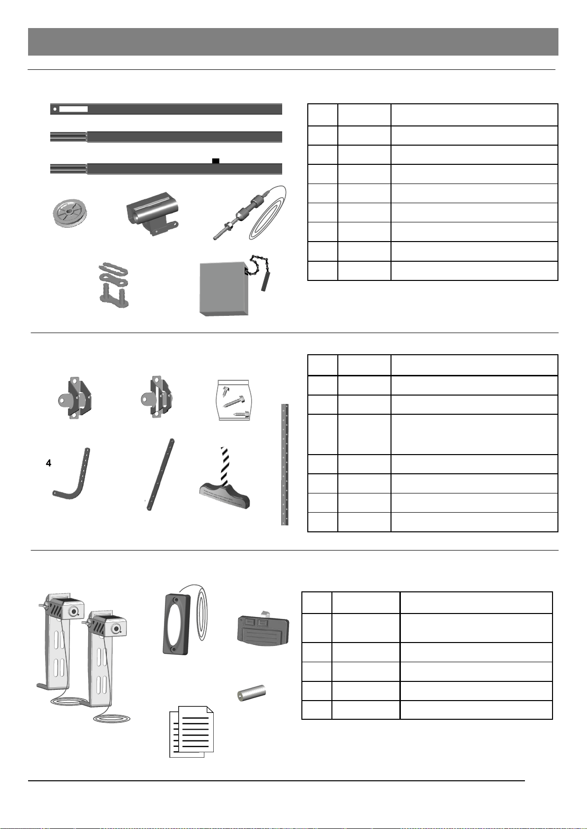
Repair Parts
Installation Parts
Rail Assembly Parts
Accessories
Part No. Name / Description Item
24911 Rail—Header Segment 1
24982 Rail—Middle segment 2
24984 Rail—End segment with Stop Bolt 3
24929 Pulley 4
24927 Trolley 5
24928 Trolley Shaft and Cable 6
24907 Master Link Set 7
8 24908 Chain
Item Part No. Name / Description
1 24919 Header Bracket
2 24917 Door Bracket
3 24925
Hardware Bag
(Installation hardware shown on P.3)
4 24921 Straight Door Arm
5 24923 Curved Door Arm
6 24924 Emergency Release Knob & Rope
7 24941 Hanging Bracket
1
2
3
4 5 6
7 8
1
2
3
4 5 6 7
1
2
5
23
Item Part No. Name / Description
1 24913
Photo Eye Safety System
(Emitter + Sensor with Brackets)
2 24915 Push Button
3 24127 Hand-held Transmitter
4 24939 12V alkaline battery
5 24000-M Owner’s manual
3
4
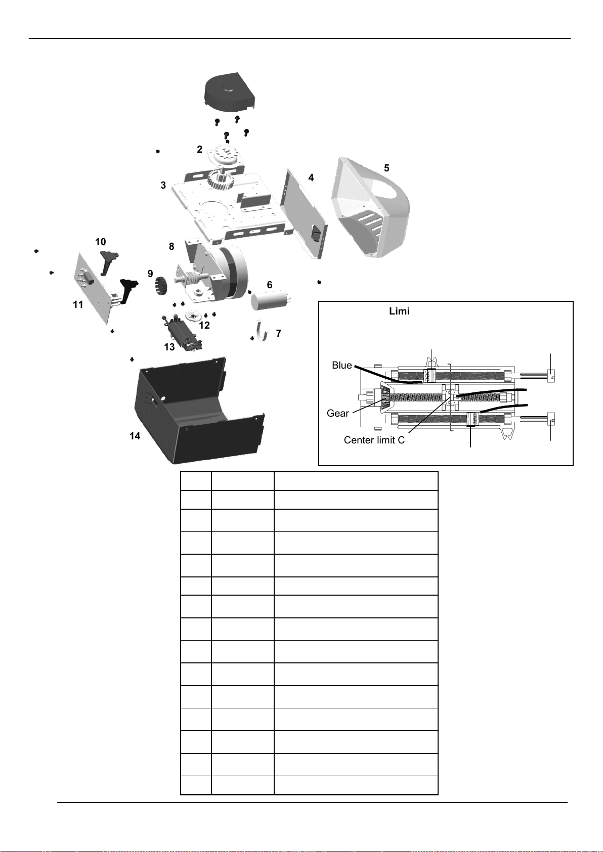
Part No. Name / Description Item
24935 Sprocket Cover 1
24934 Sprocket and gear assembly 2
*
Chassis 3
*
Lamp plate 4
24805 Lamp Dome 5
*
Capacitor 6
*
Capacitor holder 7
8
*
Motor assembly
9 24933 RPM wheel
10
*
Logic Board holder
11 24931 Logic Board
12
*
Limit system driving gear
13 24936 Limit system assembly
14 24937 Opener cover
Green
Screw
Gear
Close limit Contact
Open limit Contact
Center limit Contact
Red
Screw
Orange
Blue
Green
Limit System Assembly
1
2
3
4
5
6
7
8
9
11
10
12
13
14
Opener Assembly Parts
* Should be replaced by qualified technician only
24

Customer First Name:
Customer Last Name:
Customer Address:
Phone Number:
Email Address:
Place of Purchase:
Date of Purchase:
Serial Number:
Model Number:
Commercial Application: Yes No
Did purchaser install the product: Yes No
If no, who installed the product?:
REGISTRATION CARD
City:
Zip Code:
State:
LIMITED WARRANTY AND LIMITATION OF LIABILITY
Notice: This product is not warranted for commercial use
Decko Products warrants this product, to the original purchaser, for the initial residence in which it is installed (upon verification that it is installed correctly) to be free from
defects in materials and or workmanship for a period of 1 YEAR from the date of purchase. The motor is warranted to be free from defects in materials and or workmanship
for 10 YEARS from the date of purchase. With the exception that certain components wear out upon normal use are excluded from this warranty. Examples of such
components are as follows but not limited to; chain, cable, logic board, wall panel, photo eyes, trolley and trolley system, sprocket, position encoder and brush & gear. As the
sole and exclusive remedy for a breach of this limited warranty, if the product is found to be defective by Decko Products, Decko Products, at its option, will repair the product
or replace it with an equivalent product.
LABOR, ETC. COSTS: Decko Products shall IN NO EVENT be responsible or liable for the cost of field labor or other charges incurred by any customer in removing and/or
affixing any product, part, or component thereof.
PRODUCT IMPROVEMENTS: Decko Products reserves the right to change or improve its products or any portions thereof without being obligated to provide such a
change or improvement for units sold and/or shipped prior to such change or improvement.
If this product should fail during the limited warranty period call 1-877-GDO-4402 toll free before removing product from installation. If the product is deemed by Decko
Products to contain a manufacturer’s defect covered by this limited warranty and if it is determined it cannot be fixed at the original address of installation.
Call 1-877-GDO-4402 for a RGA # and then send product post paid to:
Decko Products,
ATTN: Warranty Dept.,
2301 Traffic Street NE
Minneapolis, MN 55413
Please include a brief description of the problem and a dated proof-of-purchase receipt with any product returned for warranty repair. Defective product will be repaired or
replaced with new or factory-rebuilt parts at manufacturer’s sole option. Any costs to un-install or re-install the product are not covered by this Limited Warranty, and you are
solely responsible for any such costs which you may incur.
In order to ACTIVATE YOUR WARRANTY, the original purchaser must register the product using the form below or online at www.gdohelp.com within 30 days of
purchase. A copy of the original receipt must accompany warranty registration.
ANY ABUSE, MODIFICATION OR DISSASSEMBLY OF THIS PRODUCT VOIDS THIS LIMITED WARRANTY.
DECKO DISCLAIMS ALL OTHER EXPRESS OR IMPLIED WARRANTIES INCLUDING WARRANTIES OF MERCHANTABILITY OR FITNESS FOR A
PARTICULAR PURPOSE.
THIS LIMITED WARRANTY DOES NOT COVER ANY PROBLEMS RELATED TO THE INSTALLATION OF THE GARAGE DOOR OR GARAGE DOOR
HARDWARE. THIS INCLUDES BUT IS NOT LIMITED TO THE DOOR SPRINGS, DOOR ROLLERS, DOOR ALIGNMENT OR DOOR HINGES.
DECKO PRODUCTS SHALL NOT BE LIABLE FOR CONSEQUENTIAL OR INCIDENTAL DAMAGES THAT ARISE IN CONNECTION WITH USE, OR INABILITY
TO USE THIS PRODUCT.
This warranty shall not apply to damage due to acts of God, normal wear and tear, normal maintenance services and the parts used in connection with such
service, lightning or conditions beyond the control of Decko Products, have been subject to negligence, abuse, accident, misapplication, tampering, alteration;
nor due to improper installation, operation, maintenance, or storage; nor to excess of recommended maximums as set forth in the instructions.
Any oral statements about the product made by the seller, Decko Products, the representatives, or any other parties do not constitute warranties, shall not be
relied upon by the user, and are not part of the contract for sale. Sellers’ and Decko Products only obligation, and the buyer’s only remedy, shall be the
replacement and/or repair by Decko Products of the product as described above. Neither seller nor Decko Products shall be liable for any injury, loss or
damage, direct or incidental or consequential (including but not limited to incidental or consequential damages for lost profits, lost sales, injury to person or
property, or any other incidental or consequential loss arising our of the use or the inability to use the product, and the user agrees that no other remedy shall be
available to it. Before using the user shall determine the suitability of the product for his/her intended use and user assumes all risk and liability whatsoever in
connection therewith.
The warranty and remedy in this limited warranty is an exclusive warranty and remedy and is in lieu of any other warranty or remedy, expressed or implied,
which other warranties and remedies are hereby expressly excluded, including but not limited to any implied warranty of merchantability or fitness for a
particular purpose, to the extent either applies to a product shall be limited in duration to the periods of the expressed warranties given above
Some states do not allow the exclusion or limitation of consequential or incidental damages, so the above limitation or exclusion may not apply to you.
This limited warranty gives you specific legal rights, and you may also have other rights which vary from state to state.
Cut along dotted line and mail card to:
Decko Products,
ATTN: Warranty Dept.,
2301 Traffic Street NE
Minneapolis, MN 55413
OR REGISTER AT WWW.GDOHELP.COM

NOTES

NOTES