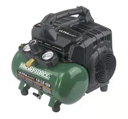
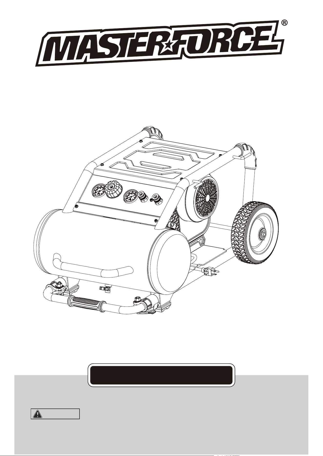
5 Gallon Air Compressor
To Reduce The Risk Of Injury, User Must Read And
Understand Operator’s Manual. Save These Instructions For Future Reference.
OPERATOR’S MANUAL
CAUTION:
Toll Free Helpline:
1-888-899-0146
E-Mail:
info@altonindustries.com

TABLE OF CONTENTS
Safety Symbols .............................................................................................................................
Safety Instructions ........................................................................................................................
Overview / Specifications ..............................................................................................................
Assembly Instructions ...................................................................................................................
Important Information ...................................................................................................................
Operating Instructions ..................................................................................................................
Maintenance .................................................................................................................................
Troubleshooting ............................................................................................................................
Exploded View ..............................................................................................................................
Parts List .......................................................................................................................................
Page 3
Table Of Contents........................................................................................................................ Page 2
Page 4-6
Page 7
Page 10
Page 9
Tool Compatibility Chart ..............................................................................................................
Page 8
Page 11-12
Page 13
Page 14-15
Page 16
Page 17
NOTES
.........................................................................................................................................
Page 18
Page 2
Page 3
SAFETY SYMBOLS
This Symbol Designates That This Tool Is Listed By Underwriters
Laboratories, To United States And Canadian Standards
This Symbol Designates That This Tool Is Listed By The Canadian
Standards Association, To United States And Canadian Standards
This Symbol Dsignates That This Tool Is Listed By The Intertek
Testing Services, To United States And Canadian Standards
This Symbol Designates That This Tool Is
Listed By Underwriters Laboratories
This Symbol Designates That This Tool Is Listed
By The Canadian Standards Association
A
Hz
W
~
n
0
lbs
.../min
Symbol
Amperes
Hertz
Watts
Alternating current
Direct current
No-load speed
Pounds
Per minute
Class II construction
Read the operator’s
Manual
Wear safety glasses
Wear hearing
Protection
Warning symbol
Name
V Volts Voltage
Current
Frequency (cycles per second)
Power
Type of current
Type or characteristic of current
Rotational speed, at no load
Weight
Revolutions, strokes, surface speed orbits,
etc. Per minute
Double-insulated construction
To reduce the risk of injury, read
and understand operator’s manual
Operation of power tool can result in
foreign objects being thrown into eyes
Wear respiratory
Protection
Use of this tool can generate dust
which may cause respiratory injury
Noise from this product
can contribute to hearing loss
Wear gloves Wear gloves to reduce risk of injury
Alerts user to warning messages
Designation / Explanation
Some of the following symbols may be used on your tool. Please study them and learn
their meaning. Proper interpretation of these symbols will allow you to operate the tool
better and safer.
SAFETY INSTRUCTIONS
The pur
pose o
f safety symbo
ls is to
attract your at
tention
to possible da
ngers.
The safety
symbo
ls, and
the explanatio
ns with
them, deserv
e your
careful attentio
n and
understanding
.
The sym
bol warnings
do not b
y themselve
s elimina
te any dang
er. The in
structions a
nd
warnings
th
ey
give are no sub
stit
ut
es for propper ac
ci
de
nt prevention me
as
ur
es.
SAFETY
A
LERT SYMB
O
L:
In
dicates DA
NGER,
WARNING
, OR CA
UTION.
May b
e use
d in conjunc
tion with
other sym
bols or p
ictographs
Be sure to rea
d and
understand all
safety
insructions in
this
manual,
includ
ing all safety a
lert sy
mbols such as
“DANG
ER”, “WARNI
NG” an
d
“CAUTI
ON”,
before using thi
s pow
er tool. Failure t
o follo
w all instruction
s list
ed
below m
ay result in e
lectric sh
ock, fire and
/or serio
us personal
injury.
SYMBO
L M
EANING
Failure
to obey
this safet
y warning
CAN res
ult in death
or
se
rious inju
ry to your
self or to o
thers. A
lways follow
the sa
fety precaut
ions to
reduce
the risk
of fir
e, electr
ic sho
ck and person
al in
jury
.
WA
RN
ING:
F
ailure to obe
y this
safety warnin
g MAY
result in per
sona
l
injury to
yourse
lf or others
or prop
erty damage
.
Alway
s f
ollow th
e safety
precauti
o
ns
to reduce the ri
sk o
f fire, electric s
hock
and personal
injury
.
CAUTION:
Failure t
o obey th
is warnin
g WILL re
sult in de
ath or seri
ous
in
jury to you
rself or t
o others
. Always
f
ol
low the saf
ety prec
autions to r
educe t
he
risk of fi
re, ele
ctric shock an
d pe
rsonal injury.
D
ANGE
R:
WARNIN
G:
Page 4
This product can expose you to chemicals including lead
which is known to the State of California to cause cancer and birth
defects or
other
reproductive
harm.Wash hands after handling. For more information go
to www.P65Warnings.ca.gov/products.
WARNIN
G:

WORK AREA SAFETY
1. Keep your work area clean and well lit.
Cluttered workbenches and dark areas invite
accidents.
2. Do not operate power tools in explosive
atmospheres, such as in the presence of
flammable liquids, gases, or dust. Power tools
create sparks which may ignite the dust or
fumes.
3. Keep bystanders, children and visitors
away while operating a power tool.
Distractions can cause you to lose control.
4. Make your workshop childproof with padlocks
and master switches. Lock tools away when not
in use.
5. Make sure the work area has ample lighting
so you can see the work and that there are no
obstructions that will interfere with safe
operation before using your power tool.
PERSONAL SAFETY
SAFETY INSTRUCTIONS
1. Know your power tool. Read the operator’s
manual carefully. Learn the power tools
applications and limitations, as well as the
specific potential hazards related to this tool.
2. Stay alert, watch what you are doing and
use common sense when operating a power
tool.
3. Do not use tool while tired or under the
influence of drugs, alcohol or medication. A
moment of inattention while operating power
tools may result in serious personal injury.
4. Dress properly. Do not wear loose clothing
or jewelry. Pull back long hair. Keep your hair,
clothing, and gloves away from moving parts.
Air vents often cover moving parts and should
also be avoided. Loose clothing, jewelry or
long hair can be caught in moving parts.
5. Avoid accidental starting. Be sure switch is
in “OFF” position before plugging in. Do not
carry tools with your finger on the switch.
Carrying tools with your finger on the switch or
plugging in tools that have the switch in the
“ON” position invites accidents.
6. Remove adjusting keys or wrenches
before turning the tool “ON”. A wrench that is
left attached to a rotating part of the tool may
result in personal injury.
7. Do no overreach. Keep proper footing
and balance at all times. Proper footing and
balance enables better control of the tool in
unexpected situations.
8. Always secure your work. Use clamps or a
vise to hold work when practical. It is safer
than using your hand and frees both hands to
operate tool.
9. Use safety equipment. Always wear eye
protection. Dust mask, non-skid safety shoes,
hard hat or hearing protection must be used
for appropriate conditions.
10. Do not use on a ladder or unstable
support. Stable footing on a solid surface
enables better control of the tool in
unexpected situations.
TOOL USE AND CARE SAFETY
1. Always use clamps or other practical ways
to secure and support the work piece to a
stable platform. Holding the work by hand or
against your body is unstable and may lead to
loss of control.
2. Do not force the tool. Use the correct tool
and blade for your application. The correct tool
and blade will do the job better and safer at
the rate for which it is designed.
3. Do not use the tool if switch does not turn
it “ON” or “OFF”. Any tool that cannot be
controlled with the switch is dangerous and
must be repaired.
4. Disconnect the plug from the power source
before making any adjustments, changing
accessories or storing the tool. Such
preventive safety measures reduce the risk of
starting the tool accidentally.
5. Never leave the tool running. Always turn it
off. Do not leave the tool until it comes to a
complete stop.
6. Store idle tools out of the reach of children
and other untrained persons. Tools are
dangerous in the hands of untrained users.
7. Maintain tools with care. Keep cutting tools
sharp and clean. Properly maintained tools
with sharp cutting edges are less likely to bind
and are easier to control.
8. Check for misalignment or binding of
moving parts, breakage of parts, and any
other condition that may affect the tool’s
operation. If damaged, have the tool serviced
WARNING:
BE SURE to read
and understand all instruction before
operating this power tool. Failure to follow
all instructions listed below may result in
electric shock, fire and/or serious
personal injury.
Page 5
SAFETY INSTRUCTIONS
EXTENSION CORDS
WARNING:
Check extension cords
before each use. If damaged replace
immediately. Never use tool with a
damaged cord since toughing the
damaged area could cause electrical
shock, resulting in serious injury.
CAUTION:
Keep the extension
cord clear of the working area. Position the
cord so that it will not get caught on
lumber, tools or other obstructions while
you are working with a power tool.
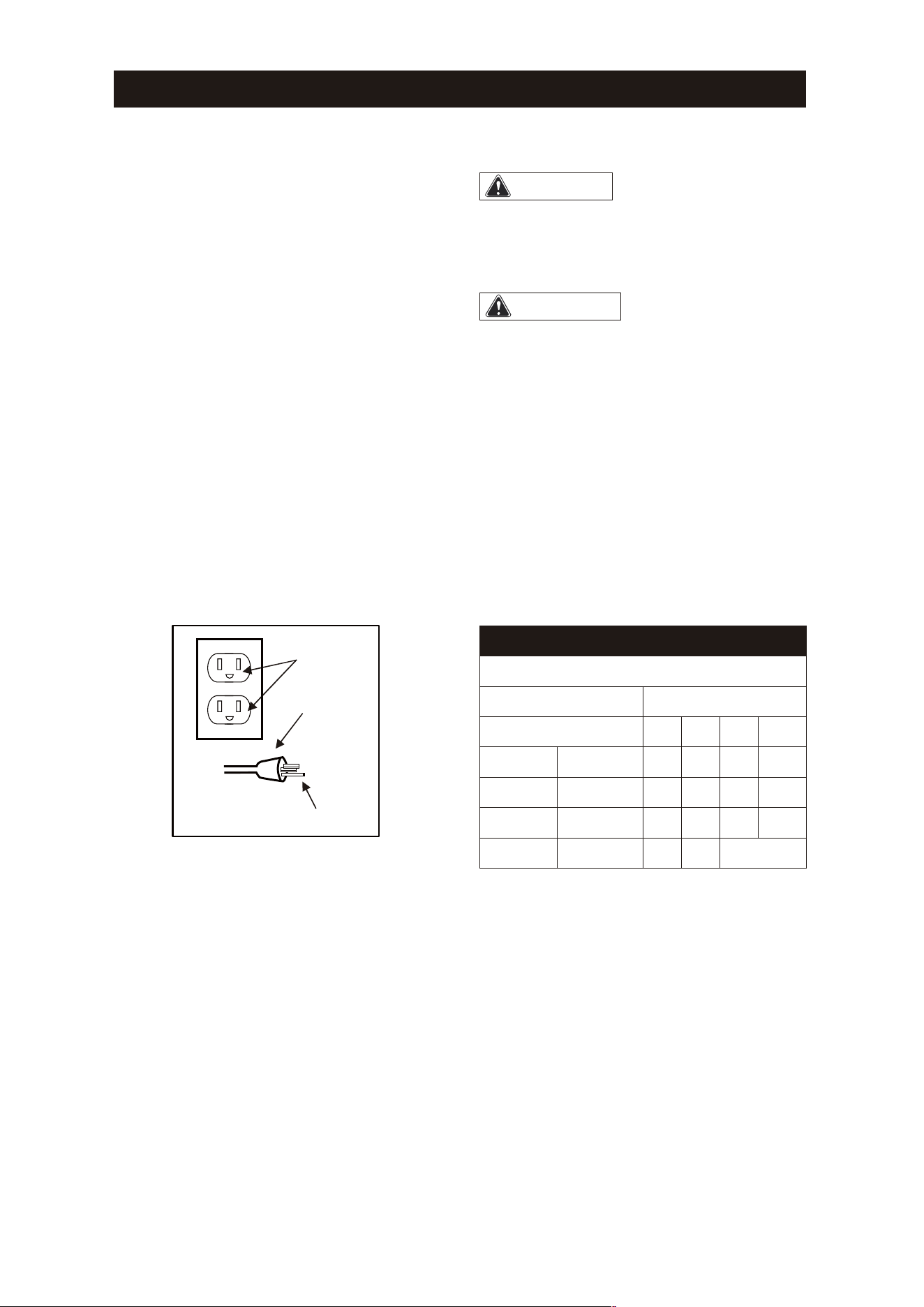
MINIMUM GAUGE FOR EXTENSION CORDS
Ampere Rating
Total Length Of Cord
(When using 120 volts only)
More Than< >Less Than
25ft. 50ft. 100ft. 150ft.
0 6 18 16 16 14
6 10 18 16 14 12
10 12 16 16 14 12
12 16 14 12
Not
Recommended
before using. Many accidents are caused by
poorly maintained tools.
9. Use only accessories that are recommended
for this tool. Accessories that may be suitable
for one tool may become hazardous when used
on another tool.
Use a proper extension cord. Only use cords
listed by Underwriters Laboratories (UL).
Other extension cords can cause a drop in
line voltage, resulting in a loss of power and
overheating of tool. When operating a power
tool outdoors, use an outdoor extension cord
marked “W-A” or “W”. These cords are rated
for outdoor use and reduce the risk of electric
shock.
Page 6
ELECTRICAL SAFETY
1. Avoid body contact with grounded surfaces
such as pipes,radiators, ranges, and
refrigerators. There is an increased risk of
electric shock if your body is grounded.
2. Do not expose power tools to rain or wet
conditions. Water entering a power tool will
increase the risk of electric shock.
3. Do not abuse the cord. Never use the cord
to carry the tool or pull the plug from an outlet.
Keep the cord away from heat, oil, sharp
edges, and moving parts.
4. Replace damaged cords immediately.
Damaged cords increase the risk of electric
shock.
Grounded
outlet
Grounding Pin
Plug
This compressor should be used on a
nominal 120V grounded circuit. Use a power
cord that is equipped with a grounding plug.
Verify that the compressor is plugged into an
outlet that has the same configuration as the
plug. Do not use an adaptor with this
compressor.
Note
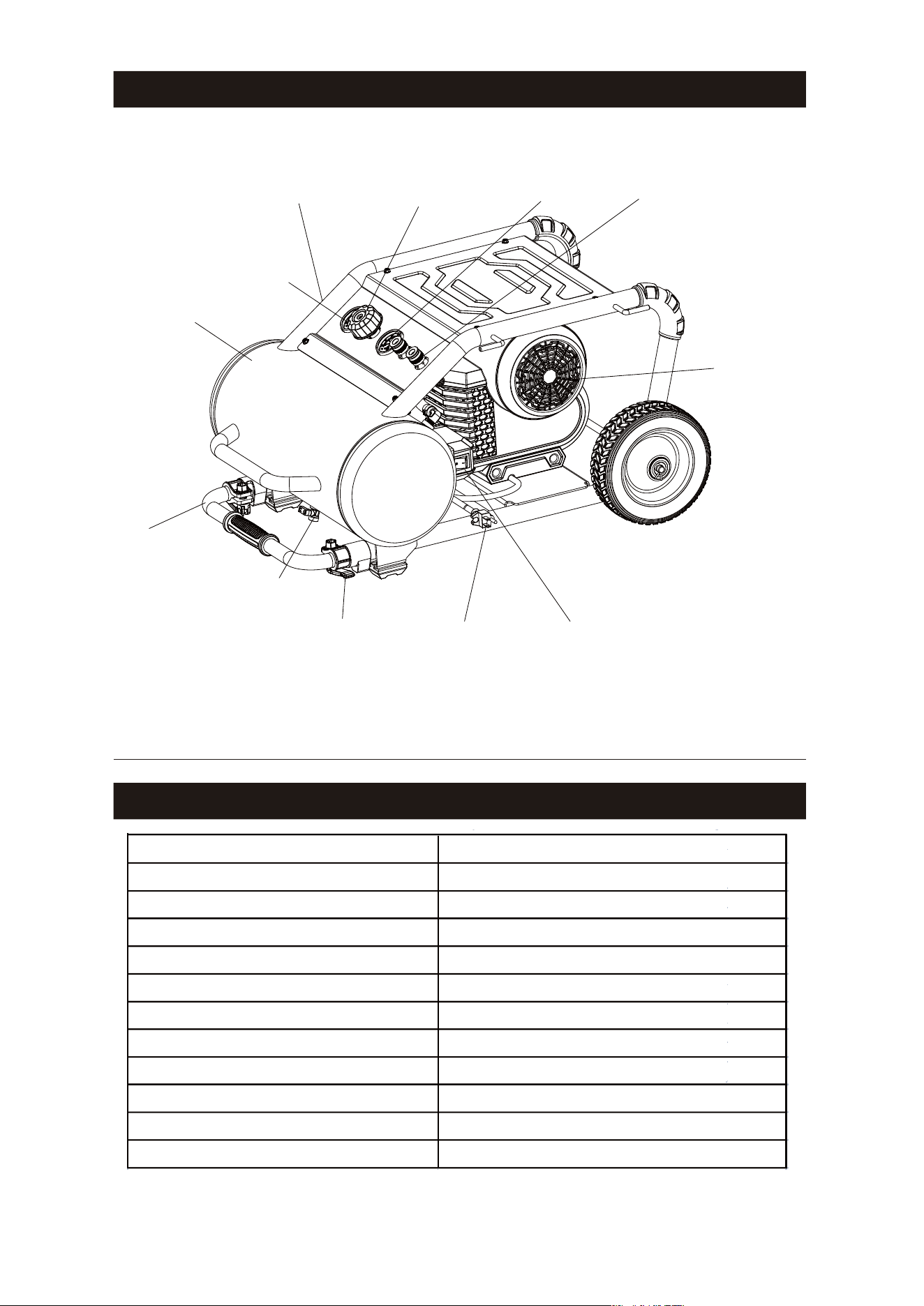
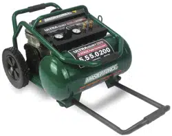
OVERVIEW
SPECIFICATIONS
Page 7
Item#:
Motor: 120 V, 60 Hz, Universal
Running Horsepower: 2.0 HP
Amperes: 15 A
Tank Size: 5.0 U.S. gallons
Air Delivery (CFM*)@40 PSI: 6.5
Air Delivery (CFM*)@90 PSI: 5.2
Cut-in Pressure(PSI): 180
Cut-out Pressure(PSI): 225
Pump Design: Oil-free, Direct Drive
Power Cord: SJ 14AWG × 12 ft
Weight:
Sliding Handle
Motor & Pump
Ball Valve
Cam Locks
Power Cord Power Switch
Regulator
Safety Valve (Not Visible)
Tank
Quick CouplersTool Gauge
207-1502
Tank Gauge
81.1 lbs
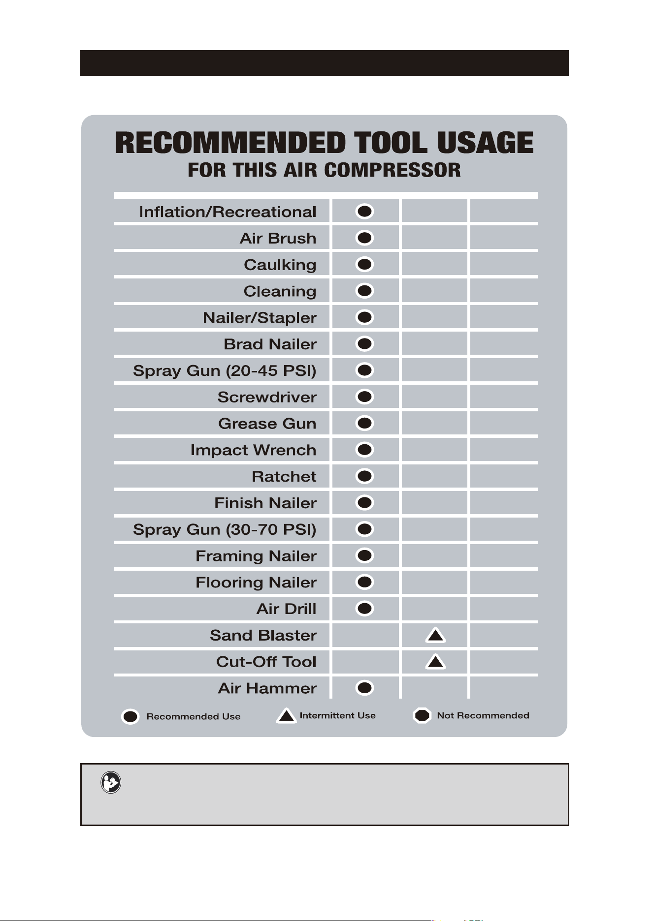
Tool Compatibility Chart
SAVE THESE INSTRUCTIONS
This manual contains important safety and operating instructions.
Read all instructions and follow them with use of this product.
Page 8

Always ensure the use of appropriately matched air tools with your Air Compressor. Be
sure that the air compressor being used can supply the appropriate volume, pressure and
delivery rate of air to the tool(s) without running continuously. Using tools or combinations
of tools that, together or separately, require more than the air compressor can deliver will
void the air compressor guarantee/warranty.
Compatible compressor and air tool - proper usage and operation
Important Information
Page 9
PRODUCT FEATURES
Electric Motor
The motor is used to power the pump. It is equipped with a thermal overload protector.
If the motor overheats for any reason, the thermal overload protector will shut it down in
order to prevent the motor from being damaged.
Air Compressor Pump
The pump compresses the air and discharges it into the tank via the piston that moves up
and down in the cylinder.
Safety Valve
This valve is used to prevent the compressor from building too much pressure. If the
pressure reaches the preset level of the motor, it will automatically pop open. You can also
pull the ring on the valve to open manually.
Power Switch
This switch turns the compressor on and off manually. ALWAYS set this switch to the OFF
position when the compressor is not being used and before unplugging.
Air Pressure Regulator
The regulator is used to adjust the pressure inside the line to the tool that is being used.
Turn the knob clockwise to increase the pressure and counter-clockwise to decrease the
pressure.
Tank Pressure Gauge
The gauge measures the pressure level of the air that is stored in the tank. It cannot be
adjusted by the operator and it does not indicate the pressure inside the line.
Tool Pressure Gauge
The gauge measures the regulated outlet pressure.
Air Outlet (Universal Coupler)
The outlet is connected to the 1/4” (6.4 mm) NPT air hose.
Air Tank Ball Valve
The ball valve is used to remove moisture from the air tank after the compressor is shut off.
Air Tank
The tank is where the compressed air is stored.
Power Cord
This compressor should be used on a nominal 120V grounded circuit. Use a power cord
that is equipped with a grounding plug. Verify that the compressor is plugged into an
outlet that has the same configuration as the plug. Do not use an adaptor with this
compressor.
This air compressor is ideal for a wide range of jobsite applications. The 5 gallon design
provides optimum pressure. It features a 2.0 HP universal motor and oil-free pump.
The procedures described in this manual are solely for this 5 gallon air compressor
at a maximum pressure of 225 PSI.
Product Features
DESCRIPTION
Air compressor
Owner’s manual
QTY ILLUSTRATION
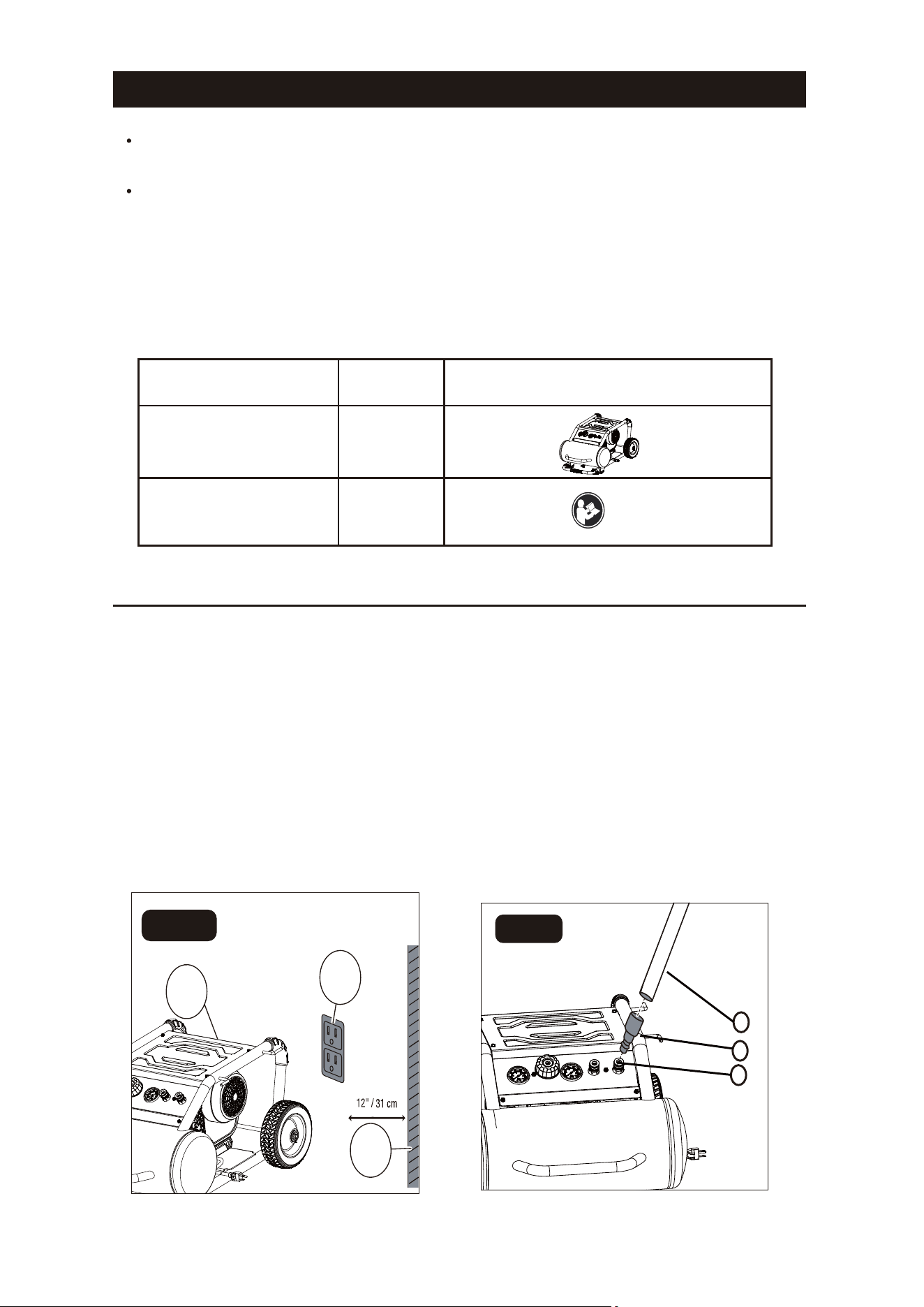
Positioning of the air compressor
1
1
2
3
1
Assembly Instructions
1
2
3
FIG. A
FIG. B
1. Position the air compressor (1) near an
electrical outlet (2)(FIG. A).
2. The compressor must be at least
12”(31cm) from any wall (3) or abstruction,
in a clean, well-ventilated area to ensure
sufficient air flow and cooling(FIG. A).
3. Place the air compressor on the floor or
a hard, level surface.
4. Connect the air hose (1) to the
compressor’s air outlet (universal coupler) (2)
with the universal quick plug (3) (FIG. B).
Note: Attach air hose and accessories
(not provided). Apply plumber’s tape on
all the threads to prevent air leakage.
Unpack the air compressor unit. Inspect the unit for damage. If the unit has been damaged,
contact the retailer immediately.
Check the air compressor’s identification label to ensure that you have purchased the
intended model and that it has the required pressure rating for its intended use.
Page 10
Operating Instructions
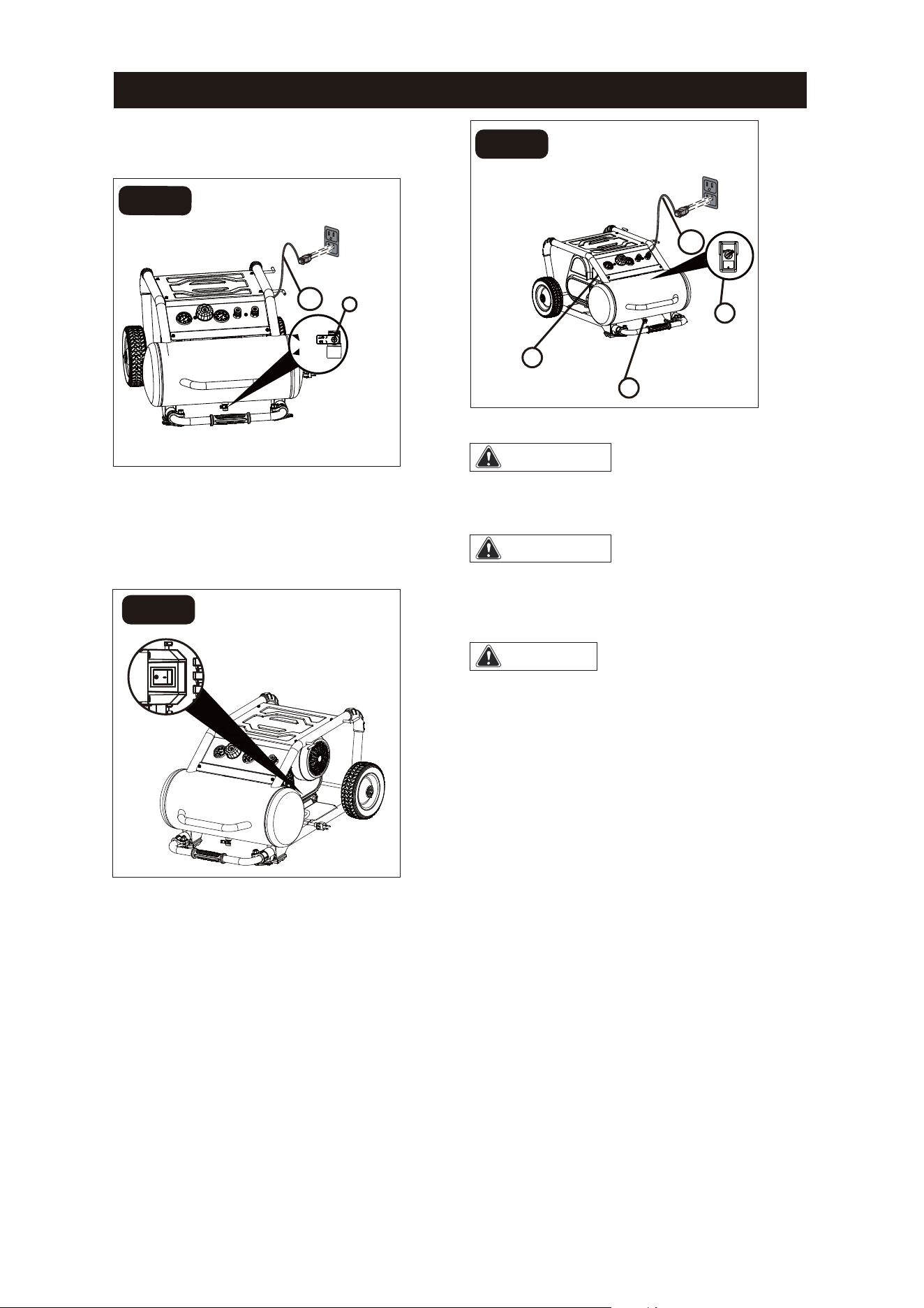
1. Set the power switch to the OFF
position (Fig. D).
FIG. D
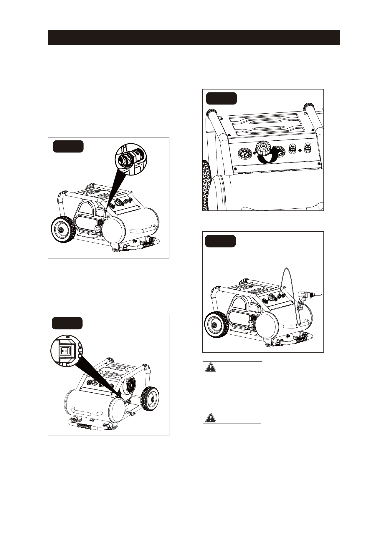
FIG. C
2. Turn the air pressure regulator knob
counter-clockwise until it stops(Fig. E).
3. Attach hose and accessories (FIG. F).
FIG. F
Hot compressor
surfaces could result in serious injury.
Allow compressor to cool before
touching.
High pressure air
could result in death or serious injury.
Never operate above maximum
operating pressure of the spray
gun or tool.
WARNING:
WARNING:
Notice
If the pump has been transported or
turned upside down (even partially),
allow the pump to sit in a normal,
Check Safety Valve
Before starting compressor, pull the
ring on the safety valve to make sure
that the safety valve operates freely.
If the valve is stuck or does not
operate smoothly, contact a trained
service technician(Fig. C).
Page 11
FIG. E
OFF
upright position (FIG. A) for
approximately 10 minutes before starting.
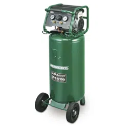
Notice
Risk of property damage. Do not
operate in vertical position! Vertical
position is for storage only!
High pressure air could
result in death or serious injury. Shut off unit,
unplug and release air pressure prior to
servicing.
High pressure air
containning water condensation could
result in minor or moderate injury. Do
not spray at any person.
Risk of serious eye injury
from moisture and debris. Always wear ANSI
Z87.1 safety goggles when opening ball
valve.
Operating Instructions
WARNING:
WARNING:
CAUTION:
5. Set the power switch to the ON position
and allow the tank pressure to build. Motor
will stop when tank pressure reaches cut-out
pressure(Fig H).
Shut down
1. Set the power switch (1) to the OFF
position.
2. Unplug the power cord (2).
3. Reduce the pressure in the tank through
the outlet hose. Pulling the safety valve ring
(3) and keeping it open will also reduce the
pressure in the tank(fig. I).
4.Set tank ball valve(4) (fig. I) to OFF to
ensure tank is drained.
1
3
4
2
FIG. I
Drain the tank
1. Set the power switch to the O (OFF)
position.
2. Turn air pressure regulator knob
counter-clockwise to set the outlet pressure
to zero.
3. Pull and hold ring on safety valve, allowing
air to bleed from the tank until air pressure is
minimized.
4. Place a suitable container under the unit to
catch any water.
5. Slightly tilt unit and turn ball valve.
counter-clockwise to open.
6. After the water has been drained,close
the ball valve(clockwise). The air compressor
can now be stored.
4. Close the tank ball valve(1) . Plug-in
the power cord(2) (FIG. G).
2
1
O
FF
O
N
F
I
G.
G
FIG. H
Page 12
ONOFF
OFF
Page 13
Check that all connections are tight. Small leaks in the tank,
hoses,connections or transfer tubes will substantially reduce the
air compressor and tool performance. Spray a small amount of
soapy water around the area of suspected leaks with a spray
bottle. If bubbles appear, repair: replace or reseal the faulty
component. Do not over-tighten any connections.
Before storing the air compressor compressor:
Drain tank (page 12).
Use an air blow gun to clean all dust and debris from the
pressor.
Disconnect and wind up the power cord.
Clean the ventilation openings on the motor enclosure with
a damp cloth.
Drain all moisture from the tank.
Pull the pressure safety valve to release all pressure from the
tank.
Cover the entire unit to protect it from moisture and dust.
Store the air compressor in a clean and dry location.
In cold weather, store the compressor in a warm building when
it is not in use. This will reduce problems related to starting the
motor and the freezing of water condensation.
Pull/actiate the safety valve daily to ensure that it is operating
properly and to clear the valve of any possible obstructions.
DESCRIPTION / REASON
SERVICE
INTERVAL
ITEM
Through normal operation of your air compressor,
conndensation water will accumulate in the tank. To prevent
corrosion of the tank from the inside, condensation must be
drained at the end of every workday. Be sure to wear protective
goggles. Relieve the air pressure in the system then open the
ball valve on the bottom of the tank to drain. Under cold
conditions it is especially important to drain the tank after each
use to reduce the chance of problems resulting from the freezing
of condensation water.
NOTE: Refer to instructions on how to drain tank (page 12).
Drain the
tank
Check the
valve
Test for
leaks
Storage
Daily
Daily
Monthly
Prior to
storing
Maintenance
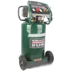
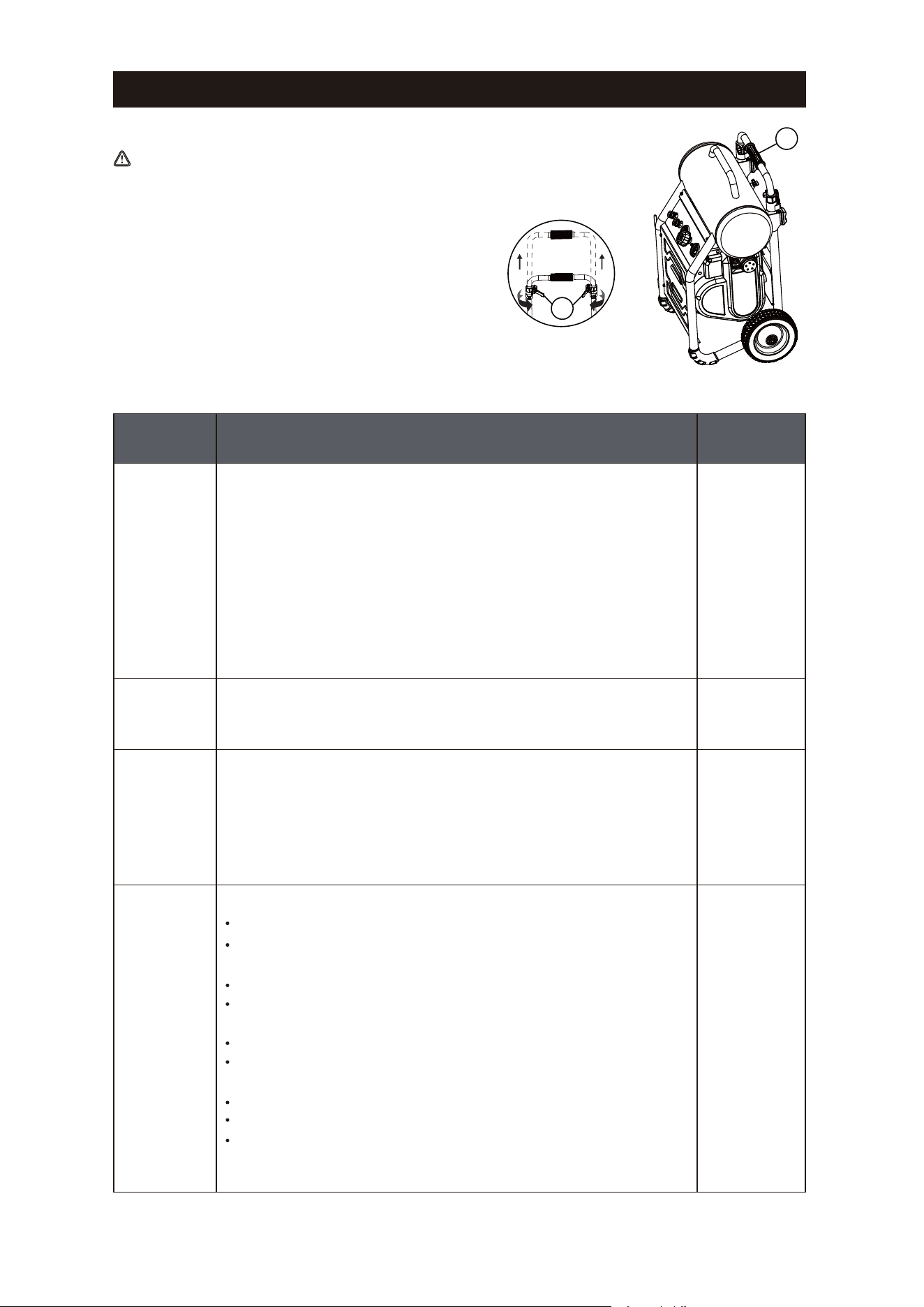
Storing and moving the Air Compressor
CAUTION
Unlock
2
For storage only
1
To avoid personal injury, DO NOT grab only the
sliding handle (1) to lift the whole unit. If you want
to lift the unit, please make sure you grab both the
tank and sliding handle (1). Use the following
instructions to use the sliding handle (1) and
wheels to move the unit.
a.Unlock the two cam locks (2) as shown in the
illustration.
b.Slide the handle (1) upward to the desired height.
c. Lock the two cam locks (2) in place.

Troubleshooting
The power cord is not plugged in.
The motor’s thermal overload
protection has tripped.
POSSIBLE CAUSE
PROBLEM
The motor will
not run or start
Plug the power cord into a grounded outlet.
Set the power switch to the ON position.The power switch is in the
O (OFF) position.
The extension cord is the wrong
wire gauge or is too long.
A fuse has blown or a circuit
breaker has been tripped.
The air tank pressure exceeds
the preset power switch limit.
The safety valve is stuck open.
Electrical connections are lose.
The motor, capacitor, or safety
valve is defective.
The motor runs
continuously
when the
power switch
is in the ON
position.
Check extension cord information (page 6)
for the proper wire gauge and cord length.
Turn the air compressor off, unplug the
power cord and wait until the motor has
cooled down. Plug in the power cord only
after the motor has cooled down, and wait
for at least 5 minutes to make sure the
thermal overload protector has recovered.
Replace the fuse or reset the circuit
breaker.
Verify that the fuse has the proper
amperage.
Check for low voltage conditions.
Disconnect any other electrical appliances
from the circuit or operate the compressor
on a dedicated circuit.
The motor will start automatically when the
tank pressure drops below the cut-in
pressure.
Clean or replace the safety valve.
Contact an authorized service center.
Contact an authorized service center.
Set the power switch to the OFF
position. If the motor does not shut off,
unplug the air compressor. If the power
switch is defective, replace it.
Check the air requirements of the
accessory that is being used. If it is higher
than the CFM (Cubic Feet per Minute )and
pressure supplied by the compressor
(page 7), a larger capacity air compressor
is needed. Most accessories are rated at
25% of actual CFM while running
continuously.
The prower switch does not
shut off the motor when the air
compressor reaches the cut-out
pressure and the safety valve
activates.
The compressor’s capacity is
not enough.
The regulator
does not
regulate the
pressure.
The regulator or its internal parts
are dirty or damaged.
Replace the regulator.
SOLUTIONS
Page 14

Troubleshooting
Prolonged excessive use of air.
POSSIBLE CAUSEPROBLEM
The pressure
is low or
there is not
enough air.
Close the ball valve.
Clean or replace the air filter element.
Check the fittings with soapy water. Tighten
or reseal leaking fittings (apply plumber’s
tape on threads). Do not over tighten.
SOLUTIONS
The tank ball valve is open.
There is a leak at one of the
fittings.
The air intake is restricted.
There is a hole in the air hose.
There is condensation in the air
tank caused by a high level of
atmospheric humidity or because
the air compressor has not been
running long enough.
The tank leaks.
The ventilation is inadequate.
Cooling surfaces are dirty.
There is
moisture in
the discharge
air.
Decrease the amount of air used.
Check the air hose and replace it if
necessary.
Replace the tank immediately. Do not
attempt to repair it.
Relocate the compressor to an area with
cool, dry and well-circulated air.
Clean all cooling surfaces on the pump
and the motor thoroughly.
Replace worn parts and reassemble using
new plumber's tape.
The
compressor
overheats.
Check for worn parts and replace them if
necessary.
Drain the air tank after each use. Drain the
air tank more often in humid weather and
use an air-line filter.
The valve is leaking.
The valve is leaking.
Page 15
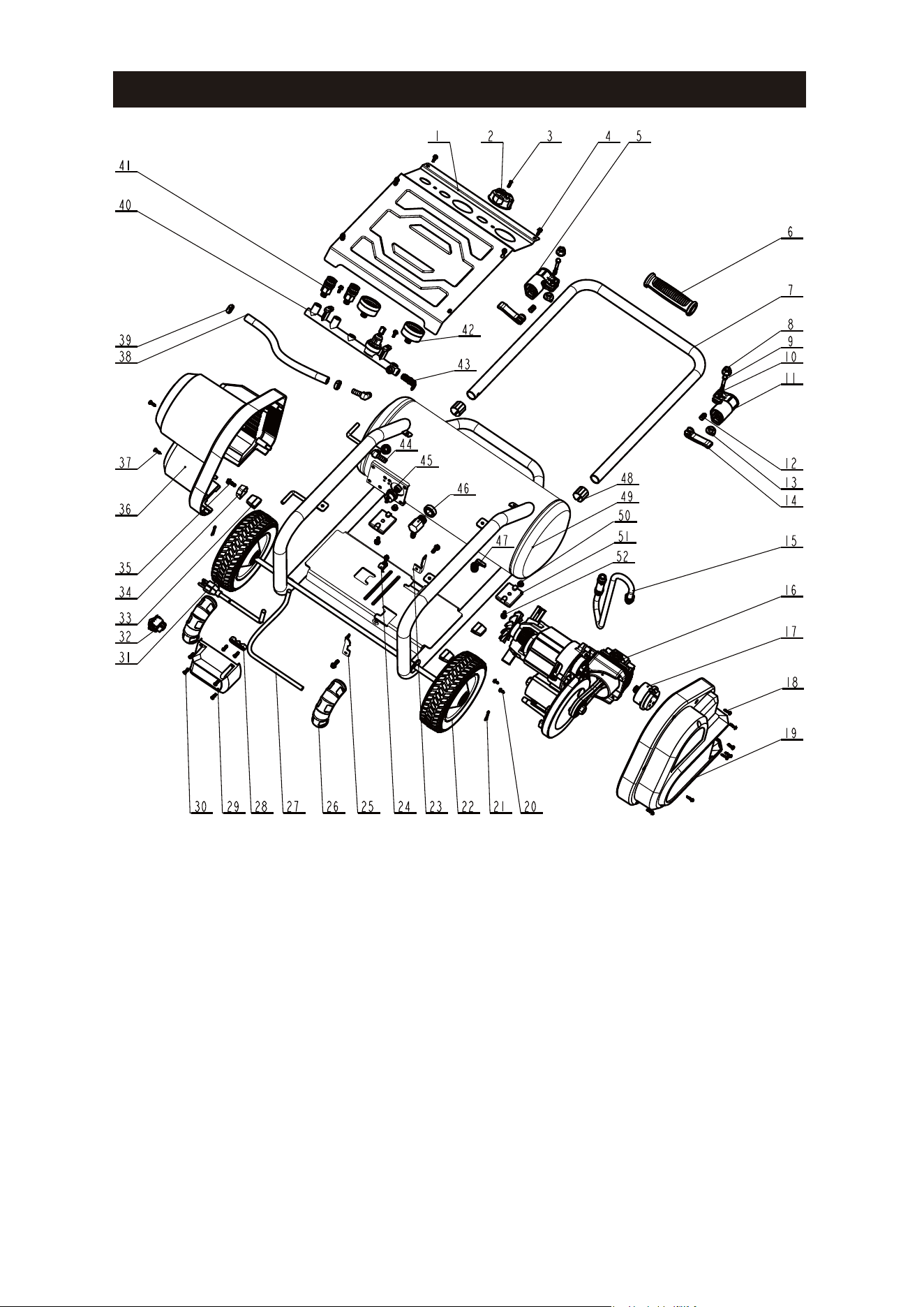
Exploded View
Page 16

Page 17
Parts List
Item# Part No. Description
1 X4561020199
2 J3264540042
3 J3894550069
4 J2020530033
5 Q3762988001
6 Q3766378001
7 J0200580003
8 Q3766398001
9 J0800470033
10 J0800500033
11 X4590590205
12 J0902530037
13 F1513700621
14 J0180380037
15 J3134560201
16 X0060590091
17 Q4474318001
18 J0994580201
19 J0801100033
20 J0024020201
21 F5013700623
22 J0782730032
23 Q4562111001
24 J2992050037
25 J0800960033
26 J3163780034
27 F9913700343
28 F3013700624
29 J6014570170
30 J3090980171
31 Q4594328001
32 A2830260480
33 J2022870040
34 X4596840206
35 D1015068139
36 D3005000067
37 J3122050032
38 F4813700643
39 J6500920028
40 J0807310040
41 Q3766408007
42 Q3766388001
43 J0780600033
Control Panel
Pressure Regulator Knob
Screw M4x10
Screw M5x12
Cam Lock (II)
Handgrip
Handle
Nut
Screw M6x34
Spring
Cam Lock (I)
Lock Nut
Plastic Washer
Lever
Rubber Hose
Motor Pump Assembly
Air Filter
Screw ST3.9x16F
Right Shroud
Bolt 8# X 9
pin
Wheel
Rear Motor Retaining Plate
Line Card
Before Motor Retaining Plate
Steel Pipe Sheath
Bleeding Tube
Clamp
Switch Box
Bolt M5x14
Power Cord
Power Switch
Cushion Pad
Retainer
Screw 1/4-20x19
Left Shroud
Screw 10#x15
Rubber Hose
Clamps
Pressure Regulator
Quick Coupler
Pressure Gauge
Safety Valve
44 D1015068139
45 D3005000067
46 J3122050032
47 F4813700643
48 J6500920028
49 J0807310040
50 Q3766408007
51 Q3766388001
52 J0780600033
Elbow Fitting
Pressure Switch
Check Valve
Ball Valve
Sliding Sleeve
Tank
Bolt M8x8
Rubber Foot
Bolt M6x16
Qty
1
1
1
9
1
1
1
2
2
2
1
2
2
2
1
1
1
6
1
3
2
2
1
1
1
2
1
1
1
6
1
1
3
1
3
1
3
1
2
1
2
2
1
2
1
1
1
2
1
2
2
2

NOTES
Page 18 Page 19

Page 18 Page 19
SAVE YOUR RECEIPTS
THIS WARRANTY IS VOID WITHOUT THEM
5 Gallon Air Compressor
WARRANTY
90-DAY MONEY BACK GUARANTEE:
This MASTERFORCE
®
brand power tool carries our 90-DAY Money Back
Guarantee. If you are not completely satisfied with your MASTERFORCE
®
brand
power tool for any reason within ninety (90) days from the date of purchase, return
the tool with your original receipt to any MENARDS
®
retail store, and we will provide
you a refund – no questions asked.
3-YEAR LIMITED WARRANTY:
This MASTERFORCE
®
brand power tool carries our famous No Hassle 3-Year
Limited Warranty to the original purchaser. If, during normal use, this
MASTERFORCE
®
power tool breaks or fails due to a defect in material or
workmanship within three (3) years from the date of original purchase, simply bring
this tool with the original sales receipt back to your nearest MENARDS
®
retail store.
At its discretion, MASTERFORCE
®
agrees to have the tool or any defective part(s)
repaired or replaced with the same or similar MASTERFORCE
®
product or part
free of charge, within the stated warranty period, when returned by the original
purchaser with original sales receipt. Not withstanding the foregoing, this limited
warranty does not cover any damage that has resulted from abuse or misuse of
the Merchandise. This warranty: (1) excludes expendable parts including but not
limited to blades, brushes, belts, bits, light bulbs, and/or batteries; (2) shall be void
if this tool is used for commercial and/or rental purposes; and (3) does not cover any
losses, injuries to persons/property or costs. This warranty does give you specific
legal rights and you may have other rights, which vary from state to state. Be
careful, tools are dangerous if improperly used or maintained. Seller’s employees
are not qualified to advise you on the use of this Merchandise. Any oral
representation(s) made will not be binding on seller or its employees. The rights
under this limited warranty are to the original purchaser of the Merchandise and
may not be transferred to any subsequent owner. This limited warranty is in lieu of all
warranties, expressed or implied including warranties or merchantability and fitness
for a particular purpose. Seller shall not be liable for any special, incidental, or
consequential damages. The sole exclusive remedy against the seller will be for the
replacement of any defects as provided herein, as long as the seller is willing or able
to replace this product or is willing to refund the purchase price as provided above.
For insurance purposes, seller is not allowed to demonstrate any of these power
tools for you.
For questions / comments, technical assistance or repair parts –
Please Call Toll Free:
1-888-899-0146
(M-F 8 am - 5 pm CT).

© 2019 Menard, Inc., Eau Claire, WI 54703 05/2019