Loading ...
Loading ...
Loading ...
5.0 optional blower installation
!
WARNING
• Risk of fire and electrical shock!
• Turn off the gas and electrical power before servicing this appliance.
• Use only Wolf Steel approved optional accessories and replacement parts with this appliance. Using
non-listed accessories (blowers, doors, louvres, trims, gas components, venting components, etc.) could
result in a safety hazard and will void the warranty and certification.
• Ensure that the fan’s power cord is not in contact with any surface of the appliance to prevent electrical
shock or fire damage. Do not run the power cord beneath the appliance.
• The wire harness provided in the blower kit is a universal harness. When installed, ensure that any excess
wire is contained, prevent it from making contact with moving or hot objects.
35.1
SPECIFIC BLOWER INSTALLATION
INSTRUCTIONS MUST BE ADDED HERE.
THIS TEMPLATE MUST BE USED WITH ANY
APPLIANCE THAT OFFERS THE BLOWER AS
AN OPTION OR COMES STANDARD WITH THE
APPLIANCE... AS PER THE STANDARD.
INSTALLATION TO BE DONE BY A QUALIFIED INSTALLER and must
be electrically connected and grounded in accordance with local codes.
In the absence of local codes, use the current ANSI / NFPA 70 National
Electrical Code.
If the appliance was not previously equipped with a blower: Route a
grounded 2-wire, 60hz power cable to the receptable / junction box. At
this point, it must be strain-relieved and insulated.
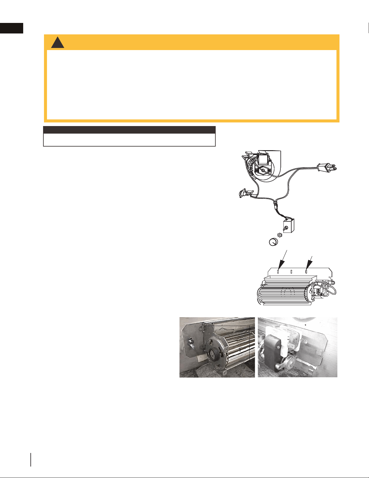
The three slots on the blower mounting bracket allow ease of adjust-
ment when attaching the blower. For a quiet running blower, do not
allow the assembly to sit on the firebox base. Slide the vibration reduc-
ing pad (A) into the clip (C) and up against the threaded stud (B) at the
other end. The blower must be able to be positioned entirely onto the
pad.
To ease installation of the blower, remove the hinge screen and valve
control door (lower louvres) from the base of the appliance.
Tilt the blower onto its side. Slide it past the controls and into the clip
(C). Secure to the threaded stud using the lock washer and wiring nut
provided. Ensure that the blower does not touch the appliance base or
the firebox.
Attach the connectors from the black and white
wires to the thermal switch and secure the thermal
switch bracket to the bottom left of the appliance
using the screws provided. Ensure that the thermal
switch touches the firebox wall.
Attach the connectors from the black and red wires
to the blower.
20
W415-0379 / E / 04.24.12
INSTALLATION TO BE DONE BY A QUALIFIED INSTALLER and must
be electrically connected and grounded in accordance with local codes.
In the absence of local codes, use the current ANSI / NFPA 70 National
Electrical Code.
If the appliance was not previously equipped with a blower:
Route a grounded 2-wire, 60hz power cable to the receptacle /
junction box. At this point, it must be strain relieved and insulated.
The three slots on the blower mounting bracket allow ease of
adjustment when attaching the blower. For a quiet running blower, do not allow the
assembly to sit on the firebox base. Slide the vibration reducing pad (A) into the
clip (C) and up against the threaded stud (B) at the other end. The blower must
be able to be positioned entirely onto the pad.
To ease installation of the blower, remove the hinge screen and valve control door
(lower louvres) from the base of the appliance.
Tilt the blower onto its side. Slide it past the controls and into the clip (C).
Secure to the threaded stud using the lock washer and wing nut provided.
Ensure that the blower does not touch the appliance base or the firebox.
Attach the connectors from the black and white
wires to the thermal switch and secure the
thermal switch bracket to the bottom left of the
unit using the screws provided. Ensure that the
thermal switch touches the firebox wall.
Attach the connectors from the black and red
wires to the blower.
black
white
red
VARIABLE
SPEED
SWITCH
BLOWER
THERMAL
SWITCH
SLOTS
ELONGATED
A
B
C
6.0 OPTIONAL BLOWER INSTALLATION
!
WARNING
RISK OF FIRE AND ELECTRICAL SHOCK.
TURN OFF THE GAS AND ELECTRICAL POWER BEFORE SERVICING THIS APPLIANCE.
USE ONLY WOLF STEEL APPROVED OPTIONAL ACCESSORIES AND REPLACEMENT PARTS WITH
THIS APPLIANCE. USING NON-LISTED ACCESSORIES (BLOWERS, DOORS, LOUVRES, TRIMS, GAS
COMPONENTS, VENTING COMPONENTS, ETC.) COULD RESULT IN A SAFETY HAZARD AND WILL
VOID THE WARRANTY AND CERTIFICATION.
ENSURE THAT THE FAN’S POWER CORD IS NOT IN CONTACT WITH ANY SURFACE OF THE
APPLIANCE TO PREVENT ELECTRICAL SHOCK OR FIRE DAMAGE. DO NOT RUN THE POWER
CORD BENEATH THE APPLIANCE.
THE WIRE HARNESS PROVIDED IN THE BLOWER KIT IS A UNIVERSAL HARNESS. WHEN
INSTALLED, ENSURE THAT ANY EXCESS WIRE IS CONTAINED, PREVENTING IT FROM MAKING
CONTACT WITH MOVING OR HOT OBJECTS.
51.5
Refer to blower leaflet for step-by-step installation instructions.
note:
W415-0379 / G / 08.23.18
EN
22
Loading ...
Loading ...
Loading ...