Loading ...
Loading ...
Loading ...
15.1
This appliance shall not be installed in a confined space or unusually tight construction unless provisions are provided for
adequate combustion and ventilation air.
The National Fuel Gas Code, ANSI Z223.1 / NFPA 54 defines a confined space as a space whose volume is less than 50
cubic feet per 1,000 Btu per hour (4.8 m3 per kw) of the aggregate input rating of all appliances installed in that space
and an unconfined space as a space whose volume is not less than 50 cubic feet per 1,000 Btu per hour (4.8 m3 per
kw) of the aggregate input rating of all appliances installed in that space. Rooms communicating directly with the space
in which the appliances are installed, through openings not furnished with doors are considered a part of the unconfined
space.
To determine the volume of the room where the appliance is to be installed, multiply the width x the length x the ceiling
height of that room measured in feet. If any adjoining rooms are connected by grilles or openings such as kitchen pass-
throughs, etc., the volume of those rooms may be added to the total.
Multiply the room volume by 1000 and divide this amount by 50 to determine the maximum BTU/hr that the space can
support with adequate combustion and ventilation air.
Add the Btu/hr of all fuel burning appliances located within the space such as gas furnace, gas water appliance, etc.
Do not include direct vent gas appliances which draw their input air from the outdoors and expel their exhaust to the
outdoors.
Unusually tight construction is defined as construction where:
A) Walls and ceilings exposed to the outside atmosphere have a continuous water vapour retarder with a rating of 1
perm (6 x 10-11 kg per pa-sec-m2) or less with openings gasketed or sealed
B) Weather stripping has been added on openable windows and doors
C) Caulking or sealants are applied to areas such as joints around window and door frames, between sole plates and
floors, between wall-ceiling joints, between wall panels, at penetrations for plumbing, electrical, and gas lines, and at
other openings.
An unvented room appliance is recommended for use as a secondary heat source rather than as a primary source. Gas
combustion produces water vapour which could occur at the rate of approximately one ounce of water for every 1,000
BTU/hr of gas input. During the cold weather season, indoor humidity levels tend to be low. Consequently, this water
vapour can enhance the living space. However if a problem should occur:
A) Ensure sufficient combustion and circulation air
B) Use a dehumidifier
C) Do not use the unvented room appliance as a primary heat
source. Without sufficient fresh air for proper operation, poor fuel
combustion can result. Carbon Monoxide is a result of poor fuel
combustion.
If additional fresh air is required, use one of the methods
described in the National Fuel Gas Code, ANSI Z223.1 / NFPA54
or the applicable local code.
Room Volume = Length x Width x Height
Max BTU/hr = Room Volume x 1000 / 50
If for example:
The length of the rooms is 5 feet (1.5m),
The width of Room 1 is 10 feet (3.1m),
The width of Room 2 is 15 feet (4.6m),
The height of the rooms is 8 feet (2.4m).
Volume of Room 1: 5x10x8 = 400 cubic feet (11.16 cubic meters)
Volume of Room 2: 5x15x8 = 600 cubic feet (16.56 cubic meters)
EXAMPLE 1:
In this example, because there is no door to the adjoining room, the volume of the adjoining room may be added to the
volume of the room with the heater to get a total unconfi ned space.
The total unconfi ned space: 400 ft
3
(11.3m
3
)+ 600 ft
3
(17m
3
) = 1000 cubic feet (28.3m
3
).
Maximum BTU/h: [(1000x1000) ÷ 50] = 20,000 BTU/h
EXAMPLE 2:
If in this example a solid door separates Room 1 from Room 2, the volume of Room 2 could not be used. In this case the
maximum BTU/h would be:
Maximum BTU/h: [(400x1000) ÷50] = 8,000 BTU/h
HEIGHT
ROOM 1
ROOM 2
WIDTH
LENGTH
• If the area in which the appliance may be operated is smaller than that defined as an unconfined space or if
the building is of unusually tight construction, provide adequate combustion and ventilation air by one of the
methods described in the National Fuel Gas Code ANSI Z223.1 / NFPA 54, air for combustion and ventilation,
or the applicable local code.
• If the area in which the appliance may be operated does not meet the required volume for indoor combustion
air, combustion and ventilation air shall be provided by one of the methods described in the ANSI Z223.1 /
NFPA 54, the International Fuel Gas Code, or applicable local codes.
!
WARNING
If there are no more fuel burning appliances within this space then the 30,000 BTU/h input of the appliance is suit-
able to be installed. This also assumes that the construction of this space is not unusually tight.
15.1
This appliance shall not be installed in a confined space or unusually tight construction unless provisions are provided for
adequate combustion and ventilation air.
The National Fuel Gas Code, ANSI Z223.1 / NFPA 54 defines a confined space as a space whose volume is less than 50
cubic feet per 1,000 Btu per hour (4.8 m3 per kw) of the aggregate input rating of all appliances installed in that space
and an unconfined space as a space whose volume is not less than 50 cubic feet per 1,000 Btu per hour (4.8 m3 per
kw) of the aggregate input rating of all appliances installed in that space. Rooms communicating directly with the space
in which the appliances are installed, through openings not furnished with doors are considered a part of the unconfined
space.
To determine the volume of the room where the appliance is to be installed, multiply the width x the length x the ceiling
height of that room measured in feet. If any adjoining rooms are connected by grilles or openings such as kitchen pass-
throughs, etc., the volume of those rooms may be added to the total.
Multiply the room volume by 1000 and divide this amount by 50 to determine the maximum BTU/hr that the space can
support with adequate combustion and ventilation air.
Add the Btu/hr of all fuel burning appliances located within the space such as gas furnace, gas water appliance, etc.
Do not include direct vent gas appliances which draw their input air from the outdoors and expel their exhaust to the
outdoors.
Unusually tight construction is defined as construction where:
A) Walls and ceilings exposed to the outside atmosphere have a continuous water vapour retarder with a rating of 1
perm (6 x 10-11 kg per pa-sec-m2) or less with openings gasketed or sealed
B) Weather stripping has been added on openable windows and doors
C) Caulking or sealants are applied to areas such as joints around window and door frames, between sole plates and
floors, between wall-ceiling joints, between wall panels, at penetrations for plumbing, electrical, and gas lines, and at
other openings.
An unvented room appliance is recommended for use as a secondary heat source rather than as a primary source. Gas
combustion produces water vapour which could occur at the rate of approximately one ounce of water for every 1,000
BTU/hr of gas input. During the cold weather season, indoor humidity levels tend to be low. Consequently, this water
vapour can enhance the living space. However if a problem should occur:
A) Ensure sufficient combustion and circulation air
B) Use a dehumidifier
C) Do not use the unvented room appliance as a primary heat
source. Without sufficient fresh air for proper operation, poor fuel
combustion can result. Carbon Monoxide is a result of poor fuel
combustion.
If additional fresh air is required, use one of the methods
described in the National Fuel Gas Code, ANSI Z223.1 / NFPA54
or the applicable local code.
Room Volume = Length x Width x Height
Max BTU/hr = Room Volume x 1000 / 50
If for example:
The length of the rooms is 5 feet (1.5m),
The width of Room 1 is 10 feet (3.1m),
The width of Room 2 is 15 feet (4.6m),
The height of the rooms is 8 feet (2.4m).
Volume of Room 1: 5x10x8 = 400 cubic feet (11.16 cubic meters)
Volume of Room 2: 5x15x8 = 600 cubic feet (16.56 cubic meters)
EXAMPLE 1:
In this example, because there is no door to the adjoining room, the volume of the adjoining room may be added to the
volume of the room with the heater to get a total unconfined space.
The total unconfined space: 400 ft
3
(11.3m
3
)+ 600 ft
3
(17m
3
) = 1000 cubic feet (28.3m
3
).
Maximum BTU/h: [(1000x1000) ÷ 50] = 20,000 BTU/h
EXAMPLE 2:
If in this example a solid door separates Room 1 from Room 2, the volume of Room 2 could not be used. In this case the
maximum BTU/h would be:
Maximum BTU/h: [(400x1000) ÷50] = 8,000 BTU/h
HEIGHT
ROOM 1
ROOM 2
WIDTH
LENGTH
• If the area in which the appliance may be operated is smaller than that defined as an unconfined space or if
the building is of unusually tight construction, provide adequate combustion and ventilation air by one of the
methods described in the National Fuel Gas Code ANSI Z223.1 / NFPA 54, air for combustion and ventilation,
or the applicable local code.
• If the area in which the appliance may be operated does not meet the required volume for indoor combustion
air, combustion and ventilation air shall be provided by one of the methods described in the ANSI Z223.1 /
NFPA 54, the International Fuel Gas Code, or applicable local codes.
!
WARNING
This would be considered a confined space since it can not support the 30,000 BTU/h input of the appliance and
it would be necessary to provide adequate combustion and ventilation air to Room 1.
2.1 gas installation
21.1
!
WARNING
• Risk of fi re, explosion, or asphyxiation. Ensure there are no ignition sources such as sparks or open fl ames.
• Support gas control when attaching gas supply pipe to prevent damaging gas line.
• Always light the pilot whether for the fi rst time or if the gas supply has run out with the glass door opened
or removed. Purging of the gas supply line should be performed by a qualifi ed service technician. Ensure
that a continuous gas fl ow is at the burner before closing the door. Ensure adequate ventilation. For gas and
electrical locations, see “dimensions” section.
• All gas connections must be contained within the appliance when complete (gas fi replaces only).
• High pressure will damage valve. Disconnect gas supply piping before testing gas line at test pressures above
1/2 PSIG.
• Valve settings have been factory set, do not change.
Installation and servicing to be done by a qualifi ed installer.
• Move the appliance into position and secure.
• If equipped with a fl ex connector, the appliance is designed to accept a 1/2” (13mm) gas supply. Without the
connector, it is designed to accept a 3/8” (9.5mm) gas supply. The appliance is equipped with a manual shut
off valve to turn off the gas supply to the appliance.
• Connect the gas supply in accordance to local codes. In the absence of local codes, install to the current
CAN/CSA-B149.1 Installation Code in Canada or to the current National Fuel Gas Code, ANSI Z223.1 / NFPA
54 in the United States.
• When fl exing any gas line, support the gas valve so that the lines are not bent or kinked.
• The gas line fl ex-connector should be installed to provide suffi cient movement for shifting the burner assembly
on its side to aid with servicing components.
• Check for gas leaks by brushing on a soap and water solution. Do not use open fl ame.
2.2 optional wall switch / thermostat
34.1
!
WARNING
• Do not connect either the wall switch, thermostat or gas valve directly to 110 volt electricity.
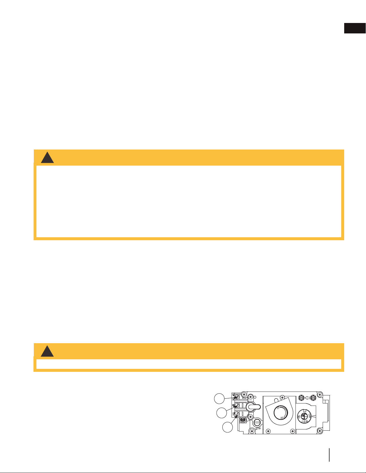
For ease of accessibility, an optional remote wall switch or millivolt thermostat may be installed in a convenient
location. Route a 2 strand, solid core millivolt wire from the valve to the wall switch or millivolt thermostat. The
recommended maximum lead length depends on wire size:
WIRE SIZE MAX. LENGTH
14 gauge (1.8mm) 100 feet (30.5m)
16 gauge (1.5mm) 60 feet (18.3m)
18 gauge (1.2mm) 40 feet (12.2m)
Disconnect the existing wires from terminals 1 and 3 (from the
ON/OFF switch) and replace with the leads from the wall switch / millivolt thermostat.
ADD IMAGE
HERE
3
1
2
SIT MILLIVOLT
ROBERT SHAW
P
I
L
O
T
3
1
2
W415-0379 / G / 08.23.18
EN
installation
11
Loading ...
Loading ...
Loading ...