
Loading ...
Loading ...
Loading ...
DFT Installation Instructions
Page: 10
“HALF OF CABLE” Marker
If the Half of Cable Marker appears BEFORE the Half-of-Area-Line previously marked on the floor, there
will likely be a cable shortage at the planned end of run�
For a cable shortage, consider the low trac areas and Border Dimension� Cable can be conserved
by avoiding placement in low trac areas or by increasing the border dimension� The border may be
increase to a maximum of 6" (150mm)� To do this, carefully unlace the cable from the strapping and
move the strapping away, but no further than 6" (150mm) from the wall; this will reduce cable usage�
Re-lace the cable according to the method outlined in the previous step� Do NOT increase cable spacing
by more than 3" as this will result in a cold floor!
If the “Half of Cable” Marker appears AFTER the Half-of-Heated-Area-Line previously marked on the
floor, there will likely be a cable surplus at the planned End of Run, the amount of which depends on
how far past the line the marker appears� Surplus cable may be used up by routing it into Low Trac
Areas� You may also reduce the cable spacing to 2" (2 tabs) between adjacent runs, provided there are
not more than six (6) consecutive runs
at this compressed spacing� Both methods will help to consume
the surplus cable�
!
WARNING - Do not cut cable if there is surplus cable.
Once the cable layout is complete, ensure all cable runs are suciently tight to prevent interference
during mortar troweling�
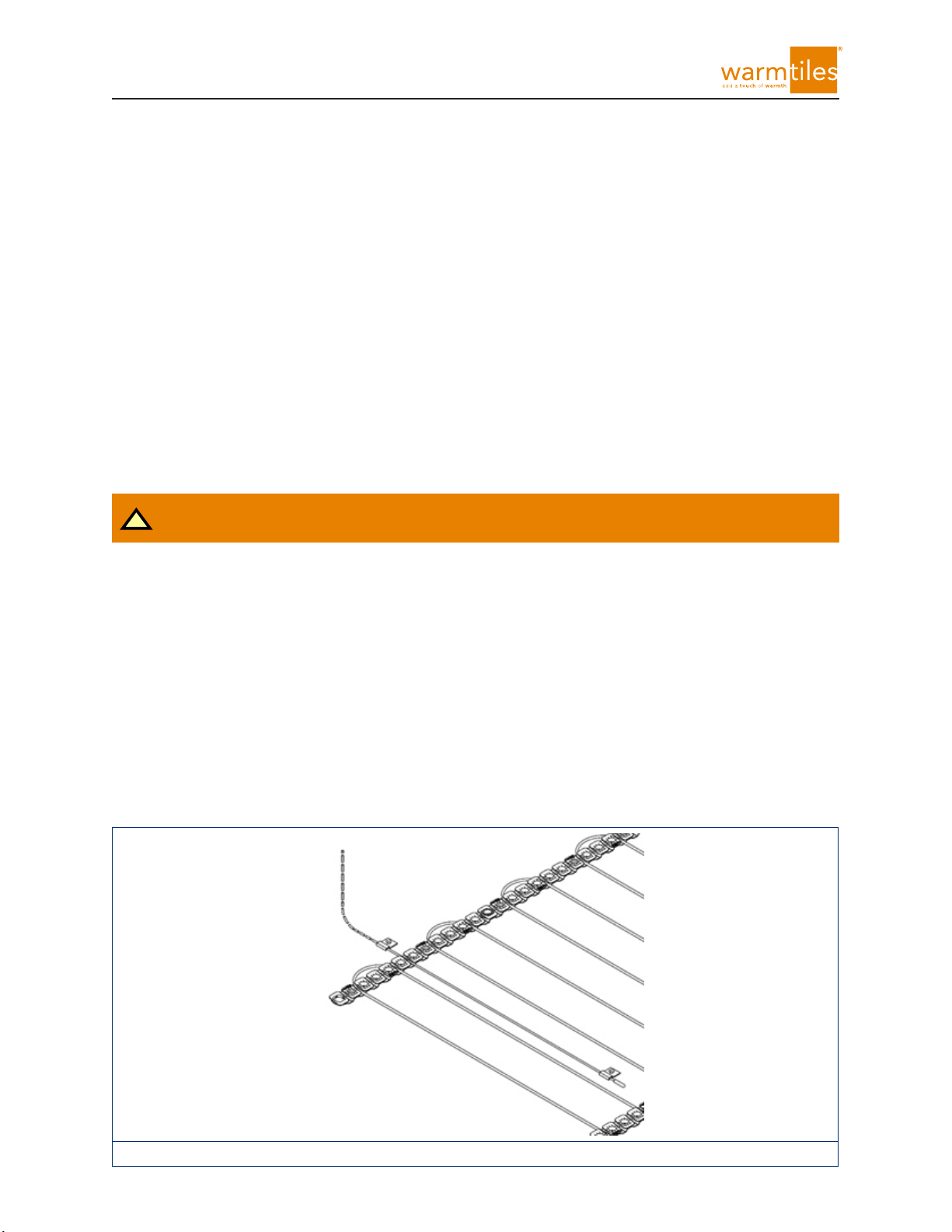
Installing Sensor Wire
The Sensor Wire must be installed midway between two adjacent Heating Cable runs� The sensor (bulb)
of the sensor wire should extend at least 6" (150mm) in from the Return Loop and lay not closer than
1/2" (13mm) to a heating cable�
If the diameter of the sensor bulb is larger than the height of the strapping, remove approximately
3/16" (5mm) of sub-floor material below the plastic clips in the same manner described for the Cold
Lead Splice� Remove all debris after this step to avoid cable damage (shown in Figure 16)�
After the cable is secured, repeat test of the system as per the section called “Verifying Resistance of
Heating Cable and Sensor�”
Figure 16
Loading ...
Loading ...
Loading ...