
Loading ...
Loading ...
Loading ...
Millbrook House, Grange Drive, Hedge End, Southampton, SO30 2DF
0844 879 3587
dimplex.co.uk | gdcgroup.co.uk
26
To open the heat pump, follow the procedure shown in gure 9;
1) Unscrew 2 screws (1) holding front bottom panel (2) using a PZ2 screwdriver
2) Pull the front bottom panel (2) down then out to remove
3) Unscrew 5 screws (3) holding the front cover (4) of the electrical box to open and then pull down
4) Remove 2 PZ2 screws (6) holding the door ap in place to access cable connections.
5) Cable access cover (7) only used on some models.
For model cable connection congurations for your heat pump model, please see gure(s) 11/12.
6) The cable access covers (5 and 7) can be opened by removing a screw to allow access to cables.
CAUTION: Ensure that cable access covers are closed correctly when not in use.
CAUTION: Follow steps in reverse order to close the heat pump. When closing the heat pump front
panel, ensure that the top and bottom panels are interlocked.
4.2.6 Electrical Connections - power and Modbus cable heat pump connections
The electrical connections to the heat pump may have one of two congurations, depending on the model.
Please see diagrams 11/12 for your conguration.
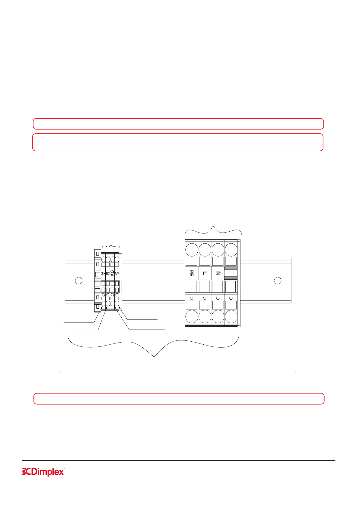
Figure 10: Heat pump electrical connections
NOTE: ‘S’ as shown in gure 10 above is the earth shield and must be connected during installation.
Controller Cable (RS485 MODBUS)
to be connected to S, OV, B, A
Mains power supply cable to
be connected to PE, L, N
Connections on this side are pre-wired
EARTH SHIELD
WHITE / Orange
BLUE / White
WHITE / Blue
Loading ...
Loading ...
Loading ...