241-0319
POWER SOURCE
For questions / comments, technical assistance or repair parts –
Please Call Toll Free: 1-866-917-4374. (M-F 8:30am-5:00pm Est.)
OPERATOR’S MANUAL
CAUTION:
To Reduce The Risk Of Injury, User Must Read And
Understand Operator’s Manual. Save These Instructions For Future
Reference.

TABLE OF CONTENTS
Safety Symbols ......................................................... Page 2
Safety Instructions ...................................................... Page 3
Overview/Specifications ................................................. Page 5
Assembly ............................................................. Page 6
Operation ............................................................. Page 7
Maintenance ........................................................... Page 8
Troubleshooting ........................................................ Page 8
Warranty ..............................................................Page10
Page 2
SAFETY SYMBOLS
Some of these following symbols may be used on this tool. Please study them and learn their
meaning. Proper interpretation of these symbols will allow you to operate the tool better and
more safely.
WARNING:
To ensure safety and reliability, all repairs should be performed by a
qualied service technician.
Symbol
Name
Designation / Explanation
V Volts Voltage
A Amperes Current
Hz Hertz Frequency (cycles per second)
W Watts Power
∿
Alternating current Type of current
�
Direct current Type or characteristic of current
n
o
No-load speed Rotational speed at no load
lbs Pounds Weight
Class II construction Double insulated construction
.../min
Per minute
Revolutions, strokes, surface speed
orbits, etc., per minute
Wear safety goggles
WARNING:
The operation of any
power tool can result in foreign objects
being thrown into your eyes, which can
result in severe eye damage. Before
beginning power tool operation, always
wear safety goggles or safety glasses
with side shields and a full-face shield
when needed. We recommend a Wide
Vision Safety Mask for use over eye-
glasses or standard safety glasses with
side shields. Always use eye protection
which is marked to comply with
ANSI Z87.1.
Page 3
The purpose of safety symbols is to attract your attention to possible dangers. The
safety symbols and the explanations with them deserve your careful attention and
understanding. The symbol warnings do not, by themselves, eliminate any danger. The
instructions and warnings they give are not substitutes for proper accident prevention
measures.
WARNING:
Be sure to read and understand all safety instructions in this manual,
including all safety alert symbols such as “DANGER,” “WARNING,” and “CAUTION”
before using this tool. Failure to follow all instructions listed below may result in electric
shock, re, and/or serious personal injury.
SYMBOL MEANING
SAFETY ALERT SYMBOL: Indicates DANGER, WARNING, OR CAUTION.
May be used in conjunction with other symbols or pictographs.
DANGER:
Indicates an imminently hazardous situation, which, if not avoided,
will result in death or serious injury.
WARNING:
Indicates a potentially hazardous situation, which, if not avoided,
could result in death or serious injury.
CAUTION:
Indicates a potentially hazardous situation, which, if not avoided,
could result in minor or moderate injury.
NOTICE:
(Without Safety Alert Symbol) Indicates a situation that may result in property
damage.
SAVE THESE INSTRUCTIONS!
SAFETY INSTRUCTIONS

Page 4
SAFETY INSTRUCTIONS
WARNING:
Read all safety
warnings and instructions!
Failure to follow the warnings and
instructions may result in electric shock,
re and / or serious injury. Save all
warnings and instructions for future
reference.
The term power tool in the warnings refers
to your mains-operated (corded) power tool
or battery-operated (cordless) power tool.
SAFETY RULES FOR POWER
SOURCE
1. Risk of re and electric shock. Dry
location use only. Do not expose the power
source to rain. Risk of injury.
2. Follow the manufacturer’s instructions
regarding operation and power for this
power source. Use of the power source
other than described in this manual could
result in a hazardous situation.
3. Maintain the power source. Check for
misalignment, breakage of parts and any
other condition that may affect the power
source operation. If damaged, have the
power source repaired before use. Use the
power source in accordance with these
instructions, taking into account the working
conditions and the work to be performed.
Use of the power source for operations
different from those intended could result in
a hazardous situation.
4. Keep the power source away from
other metal objects, such as paper clips,
coins, keys, nails, screws, or other small
metal objects that can make a connection
from one terminal to another. Shorting the
terminals together may cause burns or a
fire.
5. Your power source is rated for 12 V DC
only. Use only appropriate MASTERFORCE
battery packs. Use of any other battery
packs may create a risk of injury and fire.
6. Use only with the batteries and
chargers listed:
Battery Pack Charger
252-8016
252-8017
252-8018
252-8020
252-8021
7. To reduce the risk of electric shock,
always remove the battery pack before
cleaning or maintenance.
8 Dispose of a used battery promptly.
Keep away from children. Do not
disassemble and do not dispose of
in fire.
9. Maintain labels and nameplates. These
carry important information.
10. Follow instructions in the Maintenance
section of this manual. Use of unauthorized
parts or failure to follow Maintenance
instructions may create a risk of shock or
injury.
Page 5
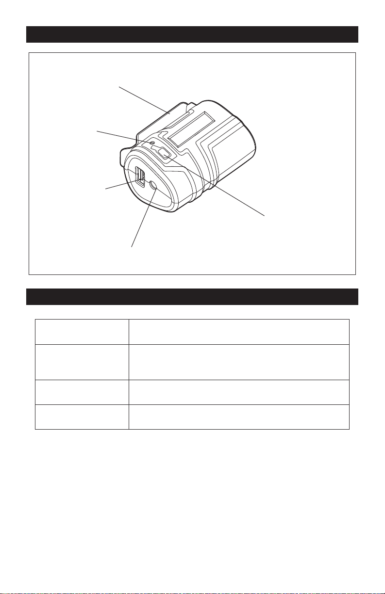
OVERVIEW
Belt clip
Fuel gauge
5V DC USB port
12V DC port
Fuel-gauge button
SPECIFICATIONS
Compatible Batteries 252-8016, 252-8017, 252-8018
12V DC Port Output
12V DC, Max. 1.1A
Suitable for Masterforce Heated Vest 241-0330, 241-0331,
241-0332, 241-0333.
5V DC USB Port Output 5V DC, Max. 1.0A
Weight 3.3 oz. (0.095kg)

Page 6
ASSEMBLY
WARNING:
If any part is broken
or missing, DO NOT attempt to attach the
battery pack until the broken or missing
part is replaced. Failure to do so could
result in possibly serious injury.
WARNING:
Do not attempt to
modify this power source or create
accessories not recommended for
use with this power source. Any such
alteration or modication is misuse and
could result in a hazardous condition
leading to possible serious injury.
CONTENTS
12V power source and instruction manual
UNPACKING
1. Carefully remove the power source and
any accessories from the carton. Make sure
that all items listed in the packing list are
included.
2. Inspect the power source carefully to
make sure that no breakage or damage
occurred during shipping.
3. Do not discard the packing material
until you have carefully inspected and
satisfactorily operated the power source.
Page 7
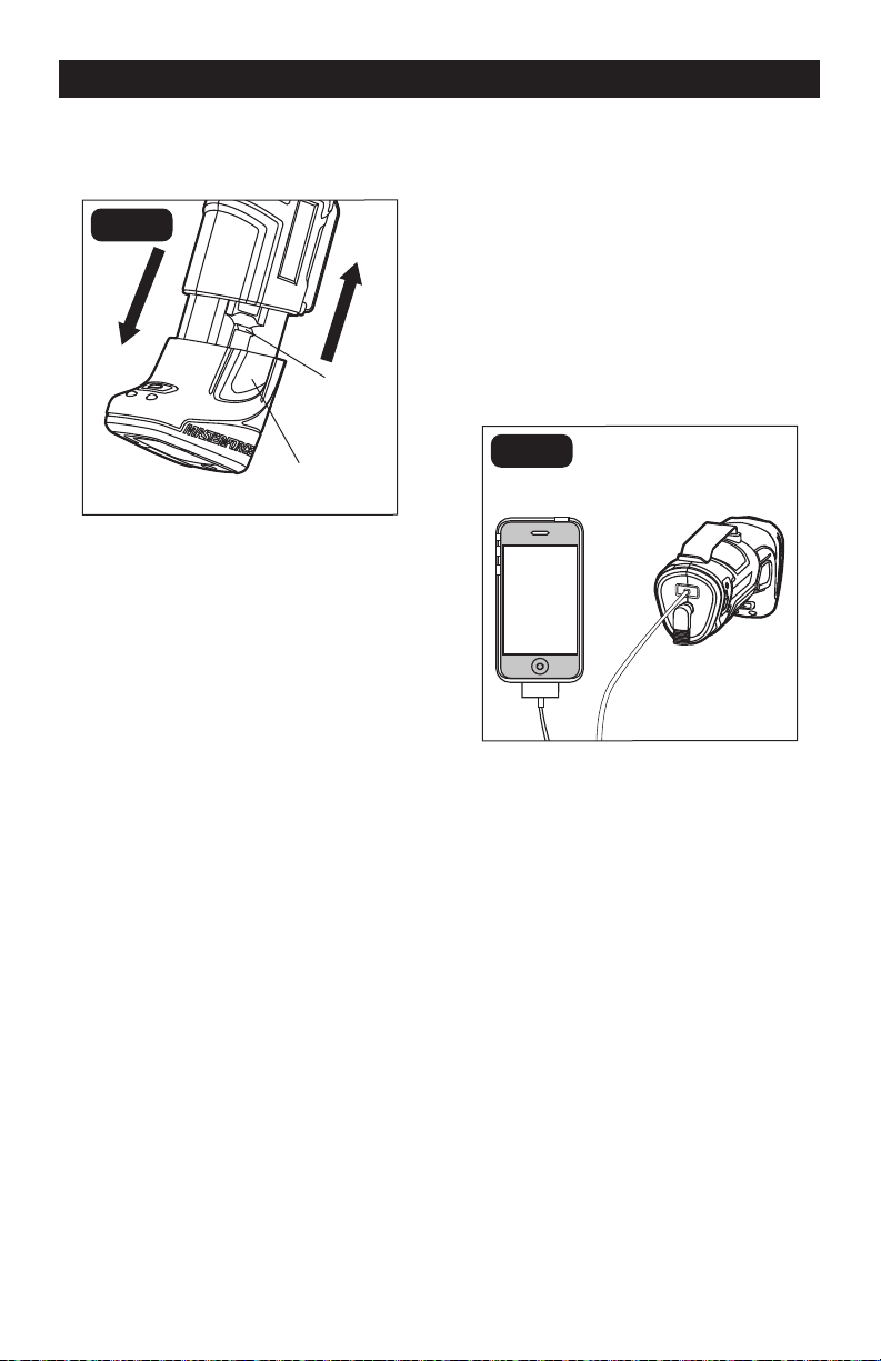
OPERATION
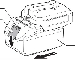
TO ATTACH BATTERY PACK
(FIG.2)
FIG. 2
Battery-release
button
Latch
Align the raised ribs on the battery pack with
the grooves of the power source, and then
attach the battery pack to the power source.
NOTICE: Make sure that the latch on the
battery pack snaps into place and the
battery pack is secured to the power
source before beginning operation.
Improper assembly of the battery
pack can cause damage to internal
components.
TO DETACH BATTERY PACK
(FIG.2)
1. Depress both battery-release buttons,
located on the sides of the battery pack, to
release the battery pack.
2. Pull the battery pack out and remove it
from the power source.
USING THE USB PORT (FIG. 3)
The 5V DC USB port can be used to charge
or power a cell phone or other personal
electronic device that uses less than 5V, 1A
of DC electric current. If the appliance draws
more than the rated output of the port, the
power source will shut off to protect the
battery pack. To restart the power port,
remove and reinstall the battery pack.
Use only appliances rated within the output
specifications for the USB port.
FIG. 3
FUEL GAUGE (FIG.4)
The power source is equipped with a fuel
gauge that indicates the battery pack’s
remaining power.
The fuel gauge will display automatically
for about 4-5 seconds when the battery
is inserted into the power source. During
operation, the fuel gauge will display when
the fuel gauge button is depressed, and will
turn off automatically about 4-5 seconds
later.
The green LED on the fuel gauge indicates
that the battery is fully charged. The orange
LED on the fuel gauge indicates that the
battery has used approximately one half of
its charge. The red LED on the fuel gauge
indicates the battery pack is depleted and
needs to be charged.

Page 8
MAINTENANCE
TROUBLESHOOTING
WARNING:
When servicing, use only identical replacement parts. Use of any
other parts may create a hazard or cause product damage. For more information, call
the toll-free helpline, at 1-866-917-4374.
PROBLEM CAUSE OF THE PROBLEM SOLUTION
The fuel gauge is not ON
when a battery pack has
been inserted.
The battery pack charge is
fully depleted.
Charge the battery pack
following the instructions
for your charger and battery
pack.
Weak contacts. Check the contacts of the
power source; make sure
they are clean and not
damaged.

Page 9
NOTES

SAVE YOUR RECEIPTS
THIS WARRANTY IS VOID WITHOUT THEM
POWER SOURCE
WARRANTY
90-DAY MONEY BACK GUARANTEE:
This MASTERFORCE
®
brand power tool carries our 90-DAY Money Back
Guarantee. If you are not completely satisfied with your MASTERFORCE
®
brand
power tool for any reason within ninety (90) days from the date of purchase, return
the tool with your original receipt to any MENARDS
®
retail store, and we will provide
you a refund – no questions asked.
3-YEAR LIMITED WARRANTY:
This MASTERFORCE
®
brand power tool carries our famous No Hassle 3-Year
Limited Warranty to the original purchaser. If, during normal use, this
MASTERFORCE
®
power tool breaks or fails due to a defect in material or
workmanship within three (3) years from the date of original purchase, simply bring
this tool with the original sales receipt back to your nearest MENARDS
®
retail store.
At its discretion, MASTERFORCE
®
agrees to have the tool or any defective part(s)
repaired or replaced with the same or similar MASTERFORCE
®
product or part
free of charge, within the stated warranty period, when returned by the original
purchaser with original sales receipt. Not withstanding the foregoing, this limited
warranty does not cover any damage that has resulted from abuse or misuse of the
Merchandise. This warranty: (1) excludes expendable parts including but not limited
to blades, brushes, belts, bits, light bulbs, and/or batteries; (2) shall be void if this
tool is used for commercial and/or rental purposes; and (3) does not cover any
losses, injuries to persons/property or costs. This warranty does give you specific
legal rights and you may have other rights, which vary from state to state. Be
careful, tools are dangerous if improperly used or maintained. Seller’s employees
are not qualified to advise you on the use of this Merchandise. Any oral
representation(s) made will not be binding on seller or its employees. The rights
under this limited warranty are to the original purchaser of the Merchandise and may
not be transferred to any subsequent owner. This limited warranty is in lieu of all
warranties, expressed or implied including warranties or merchantability and fitness
for a particular purpose. Seller shall not be liable for any special, incidental, or
consequential damages. The sole exclusive remedy against the seller will be for the
replacement of any defects as provided herein, as long as the seller is willing or
able to replace this product or is willing to refund the purchase price as provided
above. For insurance purposes, seller is not allowed to demonstrate any of these
power tools for you.
For questions / comments, technical assistance or repair parts – Please Call Toll
Free at: 1-866-917-4374. (M-F 8:30am-5:00pm Est.)

06/2015
© 2015 Menard, Inc., Eau Claire, WI 54703