Loading ...
Loading ...
Loading ...
3
English
GB
FR DE ES IT NL PT DK SE FI NO RU PL CZ HU RO LV LT EE HR SI SK GR TR
OPERATION
NOTE: The drill will not run unless the rotation selector is
pushed fully to the left or right.
Avoid running the drill at low speeds for extended periods
of time. Running at low speeds under constant usage
may cause the dr ill to become o verheated. If this occurs ,
cool the drill by running it without a load and at full speed.
INTERNAL SPINDLE LOCK
The inter nal spindle loc k allows the user single-handed
control of chuck adjustments and bit changes . Squeezing
the chuc k body stops the chuc k jaws from tur ning. For
bit changes and chuc k adjustments , squeeze the chuc k
body and turn.
KEYLESS CHUCK
The dr ill has a k eyless chuck to tighten or release dr ill
bits in the chuc k jaws. The arrows on the chuc k indicate
which direction to rotate the chuck body in order to LOCK
(tighten) or UNLOCK (release) the drill bit.
WARNING
Do not hold the chuck with one hand and use the
power of the drill to tighten the chuck jaws on the
drill bit. The chuck body could slip in y our hand,
or your hand could slip and come in contact with
the rotating drill bit. This could cause an accident
resulting in serious personal injury.
TWO-SPEED GEAR TRAIN (HI-LO)
The drill has a tw o-speed gear tr ain designed f or drilling
or dr iving at LO (1) or HI (2) speeds. A slide s witch is
located on top of the dr ill to select either LO (1) or HI (2)
speed. When using drill in the LO (1) speed range, speed
will decrease and unit will ha ve more po wer and torque .
When using dr ill in the HI (2) speed r ange, speed will
increase and unit will ha ve less po wer and torque . Use
LO (1) speed for high power and torque applications and
HI (2) speed for fast drilling or driving applications.
NOTE: If you ha ve difficulty changing from one gear
range to the other, turn the chuck by hand until the gears
engage.
See Figure 6.
CAUTION:
Never change gears while the tool is r unning.
Failure to obey this caution could result in serious
damage to the drill.
QUICK MODE SELECTOR
The Quic k Mode Selector allo ws y ou to quic kly switch
from drill mode to drive mode.
In gener al, dr ill mode should be used f or dr illing and
other hea vy duty applications . Dr ive mode should be
used for driving screws mode should be used
for impact drilling.
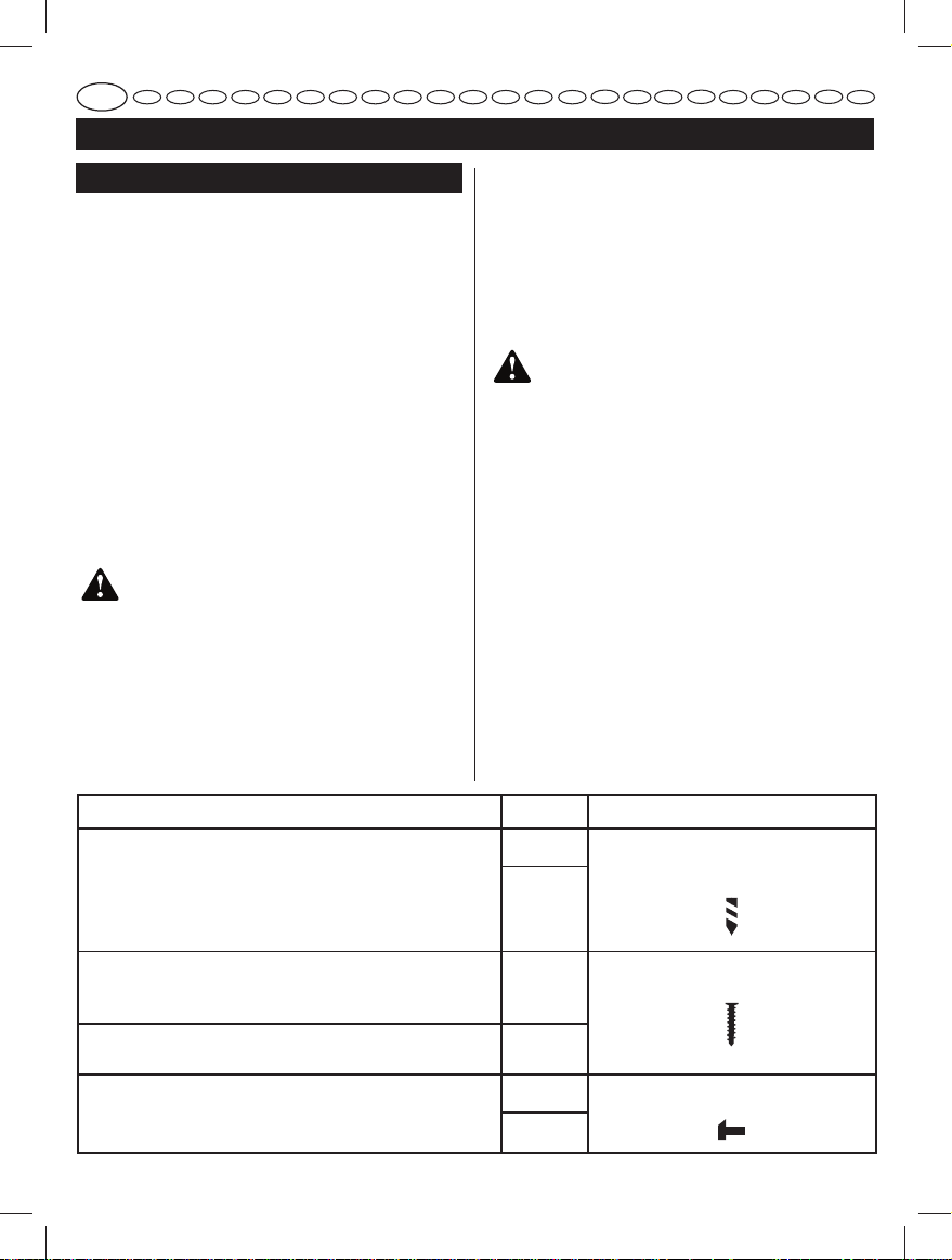
SELECTING DRIVE OR DRILL SETTING
See Figure
Using the char t below, choose correct speed and mode
the type of bit, fastener, and material you will be using.
■ Choose your APPLICATION
■ Choose the correct SPEED: (1/LOW or 2/HIGH)
■ Choose the correct MODE: (DRIVE, DRILL, OR
HAMMER)
. Hammer
5-6.
1. APPLICATION 2. SPEED 3. MODE
• Lag screws up to 9.5 mm dia. by 38.1 mm long
• Hole saw up to 50.8 mm
• Spade bits up to 38.1 mm
• Drill bits up to 12.7 mm
• Drilling into metal
• Concrete screws
1/LOW
DRILL MODE
(TORQUE ADJUSMENT NOT ACTIVE)
2/HIGH
• Drill bits up to 6.4 mm
• Deck or wood screws up to 76.2 mm long
• Self tapping screws
1/LOW
DRIVE MODE
• Deck or wood screws up to 76.2 mm long
• Small screws or delicate work that requires more control
2/HIGH
• Masonry bit up to 12.7 mm
1/LOW
HAMMER MODE
(TORQUE ADJUSMENT NOT ACTIVE)
2/HIGH
See Figure 4.
See Figure 5.
Loading ...
Loading ...