Home
Bookmarks
Home
Briggs & Stratton
Briggs & Stratton 1697439 User Manual
Page 4
Briggs & Stratton 1697439 24" 208cc Two-Stage Electric Start Gas Snow Blower
Operator's Manual - Page 4
For 1697439.
PDF File Manual
,
17 pages
,
Read Online
|
Download pdf file
More photos
General Information
Operator Safety
Features And Controls
Control Symbols And Meanings
Operation
Operating Area
Engine
Oil Recommendations
Check And Add Oil
Fuel Recommendations
Add Fuel
Start The Engine
Stop The Engine
Adjust The Discharge Chute And Deflector
Engage The Auger And Impeller
Engage The Drive Wheels
Clean A Clogged Discharge Chute
Headlight
Use The Wheel ReleaseLock Pins (if Equipped)
Maintenance And Adjustments
Maintenance Schedule
Emissions Control
Change The Engine Oil
Adjust The Skid Shoe Height
Lubricate The Control Lever Linkage
Lubricate The Discharge Chute, Deflector, And Wheel Axle
Lubricate The Auger Assembly
Lubricate The Hex Shaft And Gear
Adjusting The Auger And Traction Control Cables
Replace The Auger Shear Pins
Replace The Impeller Shear Bolts
Check The Tire Pressure
Storage
StorageFuel System
OffSeason Storage
Troubleshooting
Page 4/17
Page 1
Page 2
Page 3
Page 4
Page 5
Page 6
Page 7
Page 8
Page 9
Page 10
Page 11
Page 12
Page 13
Page 14
Page 15
Page 16
Page 17
Contents
Table of Contents
Search
Previous
Next
Troubleshooting
Bookmarks
Loading ...
Loading ...
Loading ...
4
Fea
tures
an
d
Contr
ols
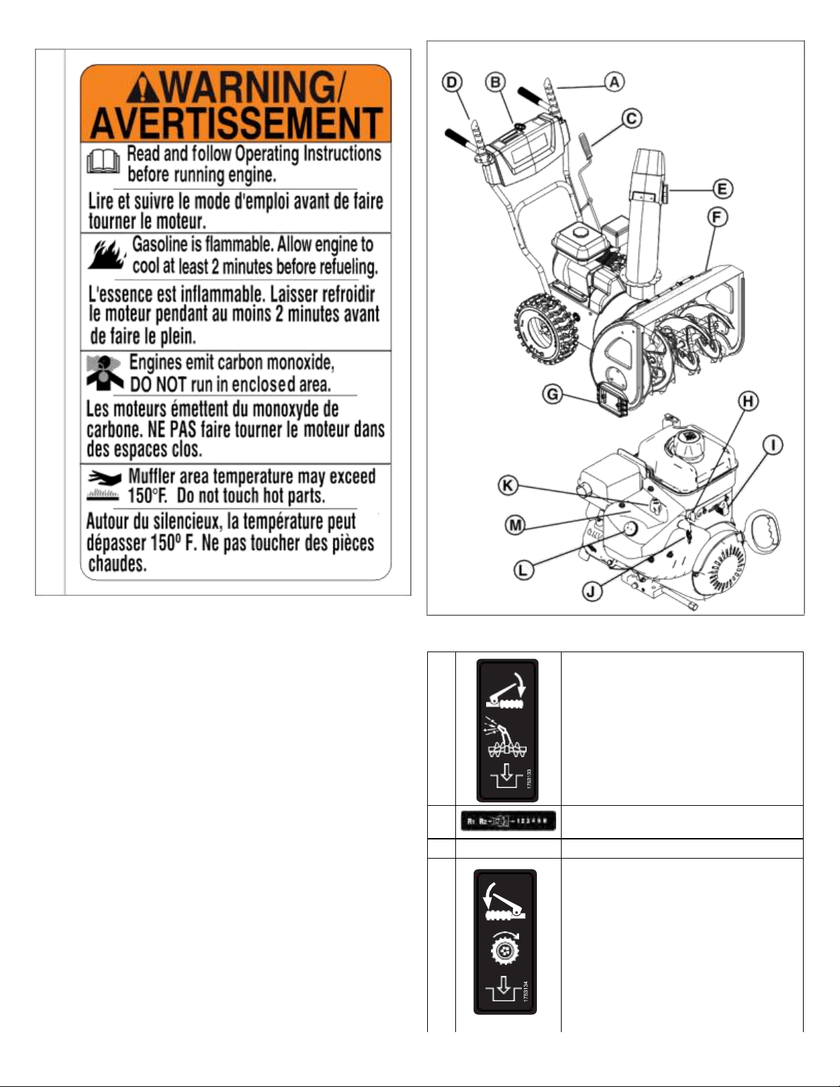
Make sure that the callout letters
in
Figure 2 agree with the
features and controls in t
he table that follows.
Cont
rol
Sym
bols
and
Me
anings
D
2
A
Auger
Control
Lever
B
Speed
Control
Lever
C
--
Chute
Rotation
Cr
ank
D
Traction Co
ntrol
Lever
Loading ...
Loading ...
Loading ...
File type: PDF
File name: 75486439_1697439.pdf
File size: 1.28 MB
File Language: English, French, Spanish
Pages: 17
Author: Briggs & Stratton
File created: 2021-08-16
Published: 2021-12-29
Updated: 2024-03-23
Verified by
Jaqueline Hayes
on 2024-03-23
Download File
Table of Contents
×
General Information
2
Operator Safety
2
Features And Controls
4
Control Symbols And Meanings
4
Operation
5
Operating Area
5
Engine
6
Oil Recommendations
6
Check And Add Oil
6
Fuel Recommendations
7
Add Fuel
7
Start The Engine
8
Stop The Engine
9
Adjust The Discharge Chute And Deflector
9
Engage The Auger And Impeller
9
Engage The Drive Wheels
10
Clean A Clogged Discharge Chute
10
Headlight
10
Use The Wheel ReleaseLock Pins (if Equipped)
10
Maintenance And Adjustments
11
Maintenance Schedule
11
Emissions Control
11
Change The Engine Oil
11
Adjust The Skid Shoe Height
12
Lubricate The Control Lever Linkage
13
Lubricate The Discharge Chute, Deflector, And Wheel Axle
13
Lubricate The Auger Assembly
13
Lubricate The Hex Shaft And Gear
13
Adjusting The Auger And Traction Control Cables
14
Replace The Auger Shear Pins
15
Replace The Impeller Shear Bolts
15
Check The Tire Pressure
16
Storage
16
StorageFuel System
16
OffSeason Storage
17
Troubleshooting
17
Search:
×
Search