Loading ...
Loading ...
Loading ...
W415-2757 / D / 11.05.20
EN
14
venting requirements
3.0 venting requirements
!
WARNING
• Risk of fi re. Maintain specifi ed air space clearances to vent pipe and appliance.
• The vent system must be supported every 3’(0.9m) for both vertical and horizontal runs. Use support ring assembly W010-
0067 or equivalent non-combustible strapping to maintain the minimum clearance to combustibles for both vertical and
horizontal runs. Spacers are attached to the inner pipe at predetermined intervals to maintain an even air gap to the outer
pipe. This gap is required for safe operation. A spacer is required at the start, middle, and end of each elbow to ensure this
gap is maintained. These spaces must not be removed.
This appliance uses a 4” (102mm) exhaust / 7” (178mm) air intake vent pipe system. Refer to the section applicable
to your installation.
For safe and proper operation of the appliance, follow the venting instructions exactly. Deviation from the minimum vertical
vent length can create diffi culty in burner start-up and/or carboning. Under extreme vent confi gurations, allow several minutes
(5-15) for the fl ame to stabilize after ignition. Although not a requirement, it is recommended for vent lengths that pass through
unheated spaces (attics, garages, crawl spaces) be insulated with the insulation wrapped in a protective sleeve to minimize
condensation. Provide a means for visually checking the vent connection to the appliance after the appliance is installed. Use a
fi restop, vent pipe shield or attic insulation shield when penetrating interior walls, fl oor or ceiling.
The vent terminal may be painted with a high temperature paint to match exterior colours. Use an outdoor paint suitable for
400°F (200°C). Application and performance of paint is the consumer’s responsibility. Spot testing is recommended.
Connections made by means of an adaptor at the appliance, as well as the connection at the vent terminal must be sealed.
RTV sealant may be used on both the inner exhaust and outer intake vent pipe joints of all other approved vent systems,
except for the exhaust vent pipe connection to the appliance fl ue collar which must be sealed using the black high temperature
sealant Mill Pac.
For all rigid vent systems is strongly recommend for all installations but required when power venting the appliance, that the
outer air intake joints are sealed using either high temperature silicone (RTV) or a suitable aluminum tape that covers each joint
in the vent system entirely around its circumference. This will ensure the best performance in every application and avoids
performance or condensation concerns that may occur in “tightly” constructed homes, particularly those in cold climates.
For optimum fl ame appearance and appliance performance, keep the vent length and number of elbows to a minimum.
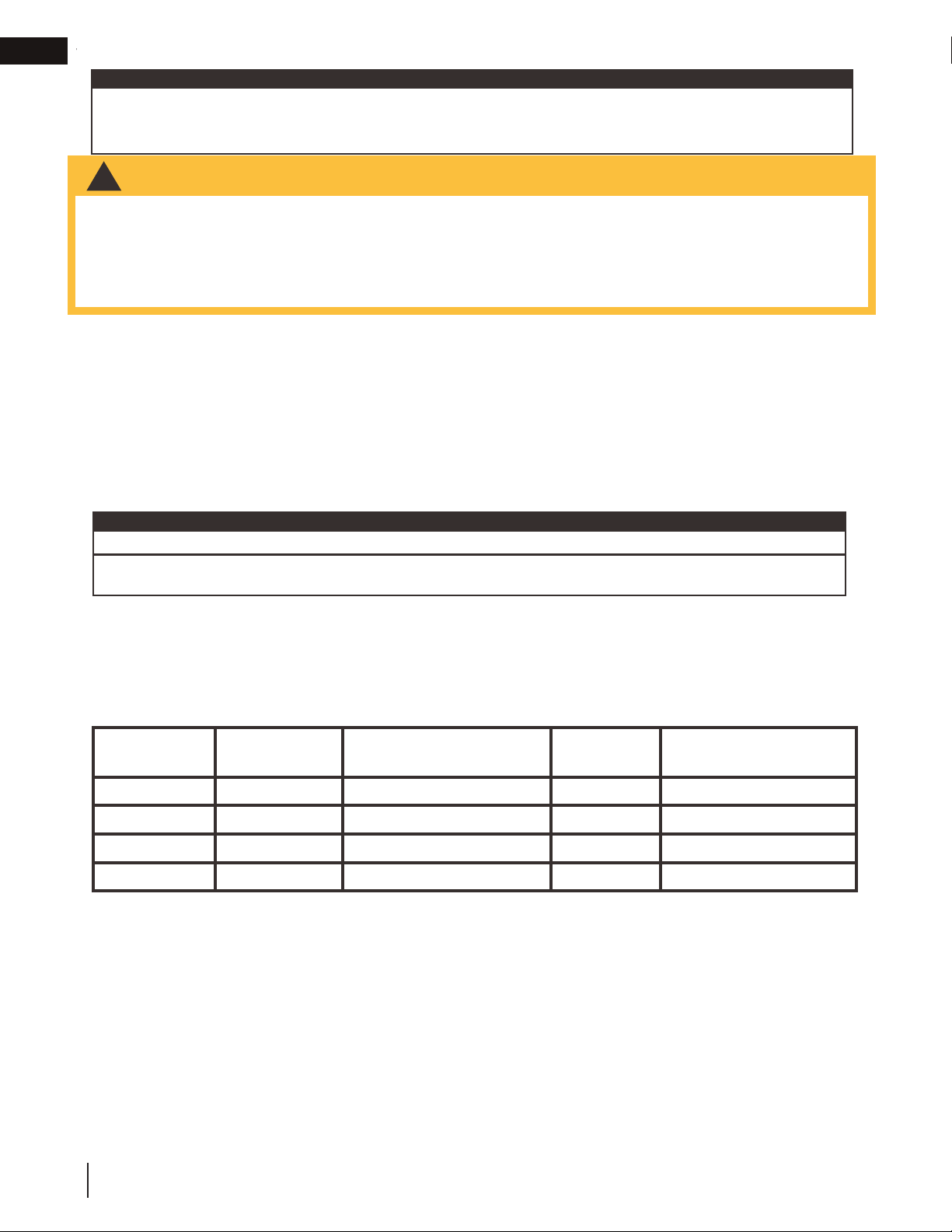
Venting System Manufacturer Starter Adapter Part Number Supplier Website
SureSeal Metal-Fab 4DNA Wolf Steel www.mtlfab.com
Direct Vent Pro Simpson DuraVent W175-0053 Wolf Steel www.duravent.com
Pro-Form BDM DVR6-STA7 BDM www.dalsinmfg.com
Direct Temp Selkirk 4DT-AAN Selkirk www.selkirkcorp.com
Use only Wolf Steel, Metal-Fab, BDM, Simpson Dura-Vent, or Selkirk Direct Temp venting components. Minimum and
maximum vent lengths, for both horizontal and vertical installations, clearances from vent pipes to combustibles and air
terminal locations as set out in this manual apply to all vent systems and must be adhered to. For Metal-Fab, BDM, Simpson
Dura-Vent, or Selkirk Direct Temp, follow the installation procedure provided with the venting components or on the website for
your venting supplier.
A starter adaptor must be used with the following vent systems and may be purchased through Wolf Steel or from the
corresponding supplier listed below:
note:
If for any reason the vent air intake system is disassembled, re-install per the instructions provided for the initial installation.
This appliance must be installed with a continuous connection of exhaust and air intake vent pipes. Utilizing alternate
constructions such as a chimney as part of the vent system is not permitted.
This template must be used in conjunction with templates 7.1.1 or 7.1.2, depending on
termination shape (i.e. round, or round and square). See appropriate templates folder.
The minimum clearances from the top of the horizontal vent pipe to combustible materials may be reduced from
3” (76mm) to 1” (25mm) in those installations with a minimum 38” (96.5cm) vertical vent rise made immediately
off the fi replace collar.
note:
When using Wolf Steel venting components, use only approved Wolf Steel rigid / fl exible components with the following
termination kits: wall terminal kit GD-222, GD-222R, ST47U or 1/12 to 7/12 pitch roof terminal kit GD-110, 8/12 to 12/12
roof terminal kit GD-111, fl at roof terminal kit GD-112 or periscope kit GD-201 (for wall penetration below grade). With fl exible
venting, in conjunction with the various terminations, use either the 5 foot (1.5m) vent kit GD-220 or the 10 foot (3.1m) vent kit
GD-330. For stoves only: wall terminal kit GD-175 (venting included).
Loading ...
Loading ...
Loading ...