attention has to be given where children and
vulnerable people are present.
If the mains lead is damaged, it must be replaced
by the manufacturer or its service agent or a
similarly qualied person in order to avoid a
hazard.
Electrical connection
WARNING – THIS APPLIANCE MUST BE EARTHED
The use of an extension lead or multi-plug adaptor is not advised when
connecting this product to the mains. Connection through these devices
could lead to a risk of overloading, overheating and even re at the extension
lead or adaptor due to inadequate connection quality.
This heater must be used on an ~ supply only and the voltage marked on
the heater must correspond to the supply voltage. This heater is tted with
a rewireable plug incorporating a 13 amp fuse. In the event of replacing
the fuse in the plug supplied, a 13 amp fuse approved by ASTA to BS 1362
must be used. If any other type of plug is used, a 15 amp fuse must be
tted in the plug, the adaptor, or at the distribution board.
IMPORTANT : If the plug is not suitable for your socket, the 13 amp plug
should be removed. Before wiring the appropriate plug, please note that
the wires in this mains lead are coloured in accordance with the following
code : GREEN AND YELLOW: EARTH
BLUE : NEUTRAL
BROWN : LIVE
Connect the GREEN AND YELLOW wire to the terminal marked ‘E’ or
by the earth symbol
, or coloured GREEN or GREEN AND YELLOW.
Connect the BROWN wire to the terminal marked ‘L’ or coloured RED.
Connect the BLUE wire to the terminal marked ‘N’ or coloured BLACK.
Using the heater
WARNING: DO NOT USE THE HEATER UNTIL THE FEET OR WALL
BRACKETS ARE FITTED CORRECTLY.
The product can be used as an installed or portable unit. Once the desired
application has been decided upon and the requirements below have been
met the product is ready to be used. Simply plug in and switch on at the
wall socket.
There are various control options available with various combinations
comprising of thermostat, switched, timer & indicating neons.
Please note – the element has been coated with a protective lm which
will burn off during the rst few minutes of use and may cause a small
amount of fuming. This is quite normal – the fumes are non-toxic and will
quickly disappear.
We recommend that you open a window to ventilate the room when using
the heater for the rst time.
Positioning the heater
Always ensure that the heater is stood on a rm, level base near to, but
not directly beneath, a suitable mains supply socket.
Ensure that curtains and furniture are not positioned close to the chosen
position, as this would create a potential re hazard.
We recommend that the heater should be wall-mounted in rooms where
children may be left unattended, see ‘Important Safety Advice’.
Important Safety Advice
WARNING: This appliance must not be used in
a bathroom.
WARNING: Do not use this heater in the
immediate surroundings of a bath, a shower or
a swimming pool.
WARNING: This heater must not be located
immediately below a xed socket outlet.
The heater carries a warning symbol to
alert the user to the risk of re that exists
if the heater is accidentally covered.
WARNING: In order to avoid a hazard due to
inadvertent resetting of the thermal cut-out,
this appliance must not be supplied through an
external switching device, such as a timer, or
connected to a circuit that is regularly switched
on and off by the utility.
This appliance can be used by children aged
from 8 years and above and persons with
reduced physical, sensory or mental capabilities
or lack of experience or knowledge if they have
been given supervision or instruction concerning
the use of the appliance in a safe way and
understand the hazards involved. Children shall
not play with the appliance. Cleaning and user
maintenance shall not be made by children
without supervision.
Children of less than 3 years should be kept
away unless continuously supervised. Children
aged from 3 years and less than 8 years shall
only switch on/off the appliance provided that
it has been placed or installed in its intended
normal operating position and they have been
given supervision or instruction concerning
the use of the appliance in a safe way and
understand the hazards involved. Children aged
from 3 years and less than 8 years shall not plug
in, regulate and clean the appliance or perform
user maintenance.
CAUTION: Some parts of this product can
become very hot and cause burns. Particular
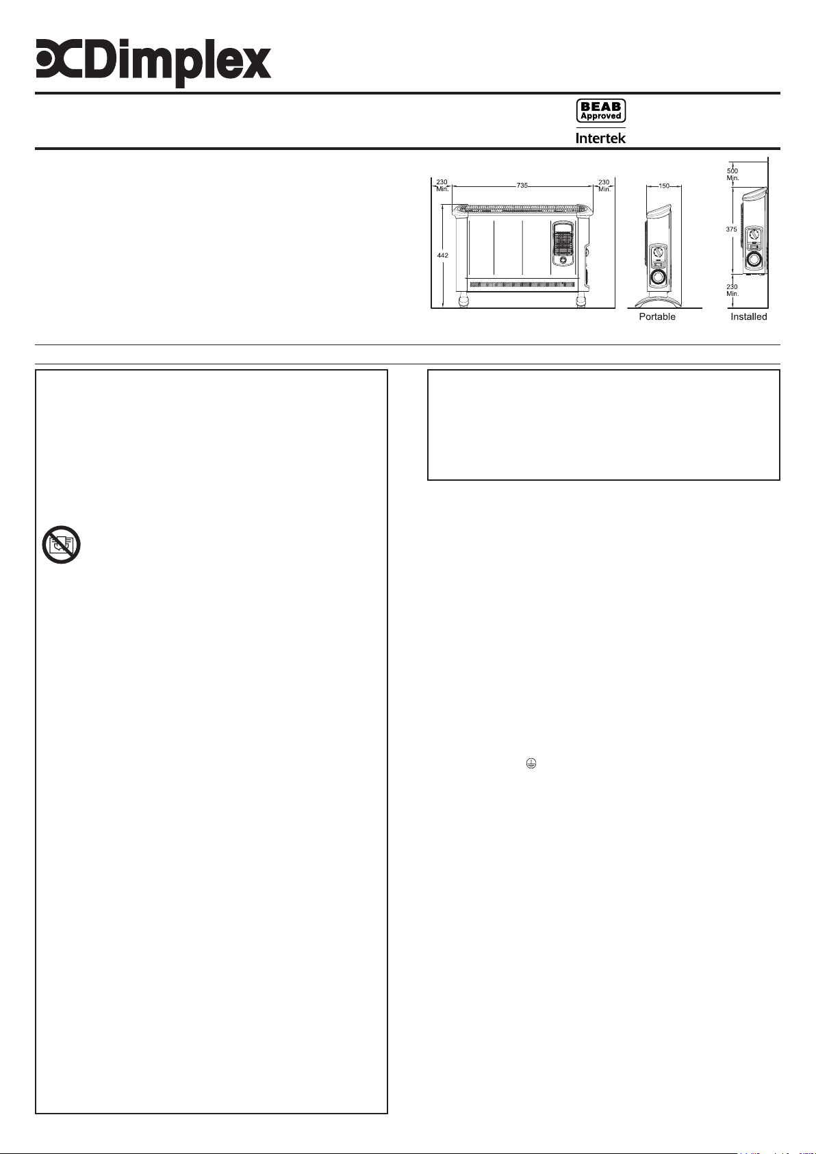
Dimensions
(Millimetres)
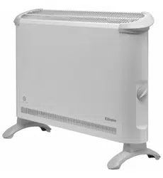
Installation and Operating Instructions
Dimplex Convector Heaters
Models :
403TS, 403TSF, 403TSTi & 403TSFTie
08/52754/1 Issue 1
Models Specication
403TS 3.0kw Thermostat & 2 heat settings & Neon.
403TSF 3.0kw Thermostat, 2 heat settings, Turbo & Neon.
403TSTi 3.0kw Thermostat, 2 heat settings, Timer & Neon.
403TSFTie 3.0kw Thermostat, 2 heat settings, Timer & Turbo.
IMPORTANT : THESE INSTRUCTIONS SHOULD BE READ CAREFULLY AND RETAINED FOR FUTURE REFERENCE
Fig. 1
Thermostat (all models)
The thermostat controls the heat output according to the room temperature.
This ensures that the heater will not produce heat unnecessarily when the
room is warm.
To set the temperature you require, gradually turn the thermostat knob
clockwise until the desired temperature is reached. Allow some time
between increments for the room temperature to stabilise.
Alternatively to heat a cold room quickly, turn the thermostat knob to the
Max position. When the room has reached the desired temperature, turn
the thermostat knob anti-clockwise until the thermostat clicks off. The heater
will then automatically maintain this room temperature.
The thermostat also has a frost protection setting marked ‘ ’. This setting is
useful in areas such as garages to prevent frost damage. If the thermostat is
set to its minimum setting ‘ ’, the heater will cycle ON and OFF to maintain
a temperature of approximately 5°C to help protect against frosty conditions.
Switches (selected models)
Some models are supplied with selector switches . There are two switch
types, one is an on/off switch and the other is a heat selection switch.
Depending on model either one or both switch may be included. The switch
operation is as follows.
On/ Off: O - Off
I - On
Heat selection I - Low heat
II - High heat
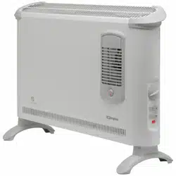
403TS Operation
This model contains an On/Off switch and a heat selection switch and
operates as follows.
When O/I switch is in position O the product is off regardless of any
other setting. When O/I switch is in position I and the I/II switch is in the
I position there is a 2kw output from the product. When O/I switch is
in position I and the I/II switch is in the II position there is a 3kW output
from the product. The indicator neon is always on when the product is
connected to the mains supply.
403TSTi Operation
This model contains a heat selection switch and an electro-mechanical
timer and operates as follows.
When the timer is switched to I and the I/II switch is in position I there is
a 2kW output from the product. When the timer is switched to I and the
I/II switch is in position II there is a 3kW output from the product. When
the timer is in the ‘ ’ position and the I/II switch is in position I there is a
2kW output from the product when the timer is set on. When the timer is
in the ‘ ’ position and the I/II switch is in position II there is a 3kW output
from the product when the timer is set on. The indicator neon is always
on when the product is connected to the mains supply.
Mechanical Timer (403TSTi)
9
8
6
5
7
15
2
21
22
20
19
18
16
17
3
4
24
23
1
11
12
10
13
14
O
I
Set the I - - slide switch on the timer (Fig.7) to:
Position
- Heating Off
Position I - Manual operation
This setting allows power to the heater
uninterrupted by the timer settings. The heat
selector switch will control the output (see
heater).
Position
- ‘Auto’ operation
DO NOT disconnect this heater from the mains
supply unless it is being taken out of use (e.g.
in summer or for storage), otherwise the timer
clock will stop.
9
8
I
10
O
Portable use
WARNING: THE HEATER SHOULD NEVER BE USED AS A PORTABLE
APPLIANCE WITHOUT THE FEET SECURELY FITTED.
WARNING: ONLY THE SCREWS SUPPLIED WITH THIS PRODUCT
SHOULD BE USED TO MOUNT THE FOOT. A MAXIMUM SCREW
LENGTH OF 10MM SHOULD BE USED.
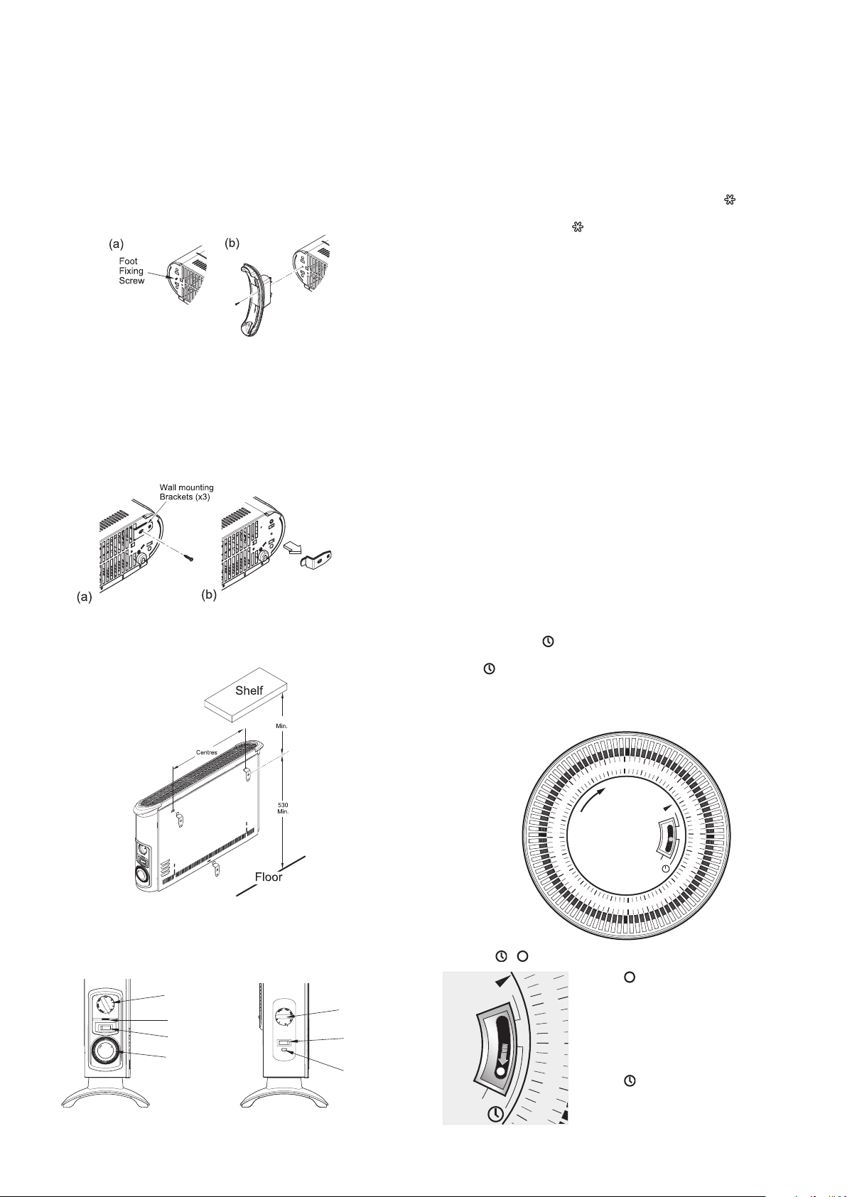
Lay the heater on its back and remove the wall mounting brackets - see
Wall mounting. Locate and remove the foot xing screw - see Fig. 2(a).
Clip the foot in place and secure using the foot xing screw.
NOTE – The wall mounting brackets must be removed before the foot
can be tted.
Wall Mounting (Installed)
Three identical wall mounting brackets are secured to the base of the heater
with a xing screw. To wall mount appliance, rst remove the brackets as
follows, lay the heater on its back and follow the sequence shown - see
Fig. 3. Identify and remove the xing screw securing the brackets located
beside mains cable as shown in (a), pull out brackets and rotate them to
disengage them from the slot and withdraw the brackets from the slot (b).
Select a suitable position, near to a mains power socket whilst ensuring
the minimum mounting clearances are maintained - see Fig. 1. Fix the
two top retaining brackets to the wall, using suitable xings – see Fig. 4.
478
574
Locate the heater on the top brackets and allow it to hang in place.
Fit the bottom bracket into the slot in the heater and then x it to the wall.
Test that the heater is now securely xed to the wall.
Controls
Model 403TSTi
Model 403TSF
Heat selector
switch
Thermostat
knob
Neon
Mechanical
Timer
Control
switch
Thermostat
knob
Neon
Fig. 6
Fig. 4
Fig. 5
Fig. 3
Fig. 2
Fig. 7
Setting the time of day
To set the time of day, rotate the timer dial clockwise (indicated by the arrow)
until the correct time of day is opposite the reference mark
(see Fig.
6). The 24-hour clock is used ; e.g. time shown for 3 pm is ‘15’ (15:00hrs).
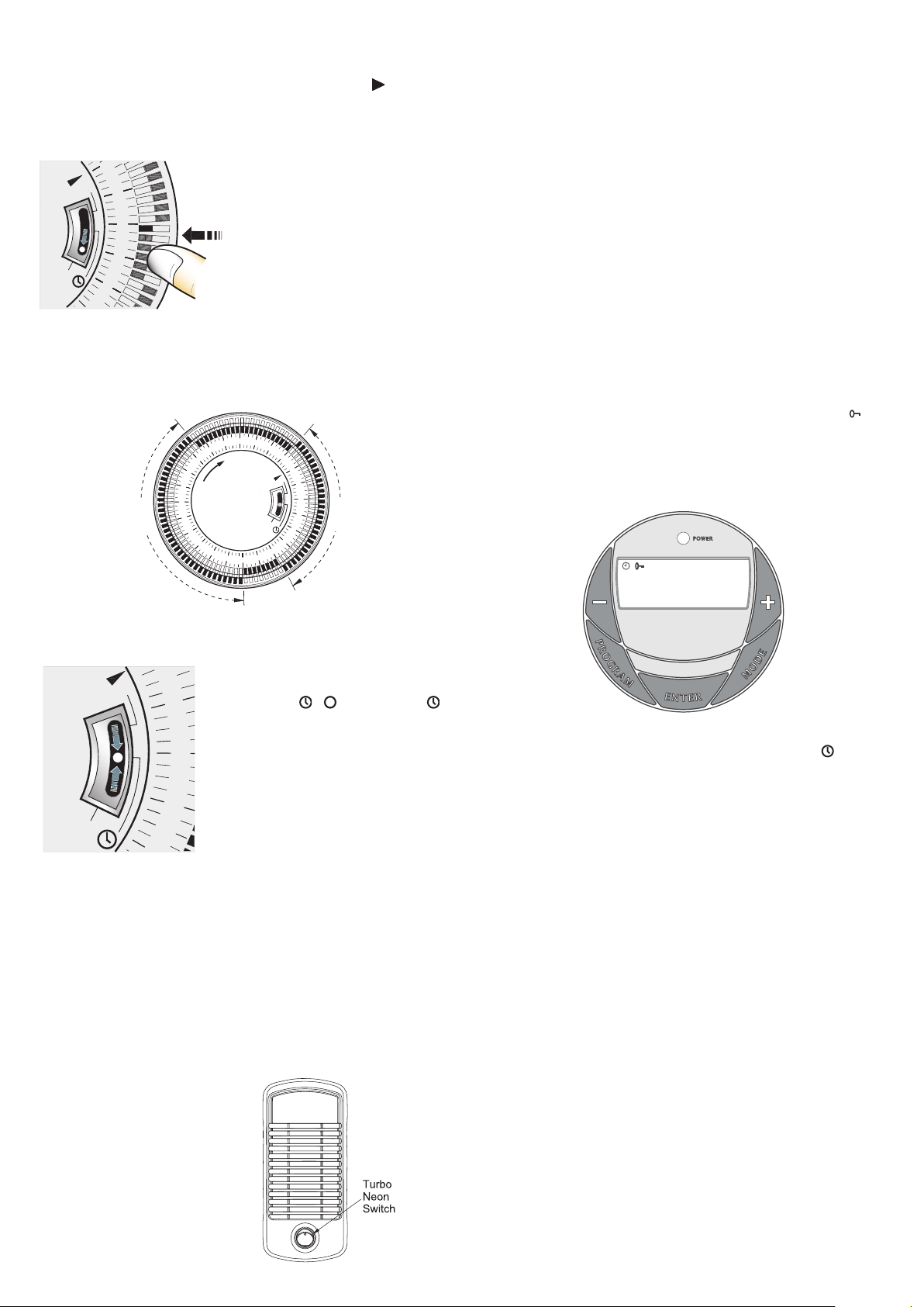
Setting the ‘Auto’ ON and OFF times
To set the timer :
1. Using your nger tip or the tip of a
pencil, push in as many segments as
necessary around the dial, according
to the times you don’t require heat –
see Fig. 8. Each segment pushed in
switches the heater OFF for that part of
the hour. All other segments will be ON.
For example, Fig. 9 shows the timer
set to switch the heater ON between
9.00am and 4.00pm and between
9.30pm and 7.00am.
2. You can select as many ON periods as you like, within the 24-hour day.
The settings will repeat every day until changed.
3. To change ON and OFF times, simply push in any ‘ON’ segments you
wish to cancel and pull out new ‘ON’ segments as required.
22
4
3
2
1
23
24
7
5
6
8
9
10
12
13
O
11
16
14
I
15
18
19
20
21
17
9.00 am -
4.00 pm
9.30 pm -
7.00 am
Switching to auto
Set the heat selector and thermostat for the
heat output required.
Check that the clock shows the correct time
of day. Set the I - - slide switch to
(see Fig. 10) - the heater will switch ON and
OFF according to the timer settings.
IMPORTANT NOTES
Remember to observe all safety warnings
when operating the heater on auto setting
unattended or attended .
If the mains supply to the heater is interrupted,
the timer clock will stop until power is
restored; reset the time of day to ensure
correct ON and OFF times.
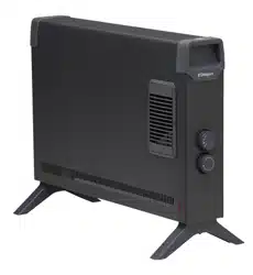
403TSF Operation
This model contains an On/Off switch and operates as follows.
When O/I switch is in position O the product is off regardless of any other
setting. When O/I switch is in position I and the turbo switch is Off there
is a 2kw output from the product. The turbo fan will be off.
When O/I switch is in position I and the turbo switch is On the heater
goes into 3kW fan boost mode. There is a 3kw output from the product.
The turbo fan will be running. The indicator neon is always on when the
product is connected to the mains supply.
Note: there is no cold blow operation on this model and all heat settings
and the turbo fan operate under the control of the thermostat
Turbo fan (Boost mode)
The turbo fan is used to boost
the airow around the room. This
circulates the heat better and
results in a reduced heat up time
and a more even heat distribution.
The turbo fan is controlled by the
neon switch on the front of the
product.
403TSFTie Operation
This model contains an On/Off switch and operates as follows.
When O/I switch is in position O the product is off regardless of any other
setting. The timer will continue to operate but cannot turn on the product
When O/I switch is in position I and the turbo switch is Off there is a 2kw
output from the product. The turbo fan will be off.
When O/I switch is in position I and the turbo switch is On the heater goes
into 3kW fan boost mode. There is a 3kw output from the product. The
turbo fan will be running. The neon indicator on the timer will only be on
when the timer is on an ‘On’ cycle.
Note: there is no cold blow operation on this model and all heat settings
and the turbo fan operate under the control of the thermostat
Digital Timer (403TSFTie) - see Fig. 12
IMPORTANT: Remember to observe all safety warnings when operating
the heater on auto setting, either attended or unattended.
The timer allows you to select ‘AUTO’ or ‘MAN ON’ by pressing the ‘MODE’
button until the required MODE appears at the bottom of the timer display.
‘AUTO’ MODE allows the heater to switch ON and OFF according to a set
24 Hour program period (see ‘Setting Programs’ section below).
‘MAN ON’ MODE allows power to the heater uninterrupted by the program
settings.
Key Lock:
If ‘ENTER’ and ‘MODE’ are pressed within 1 second, the keys will be
locked. The user will know the keys are locked as the lock symbol ‘ ’ will
be displayed on the top left hand corner of the screen. To unlock the keypad,
press ‘ENTER’ and then ‘MODE’ within 1 second.
Initial Operation
For initial use, plug the heater into a regular household power point and
turn the power on. The timer is now ready to be set up for use.
13 : 17
ON
OFF
ADVANCE
AUTO MAN ON
P1
Setting Current Time
1. Press the ‘PROGRAM’ button ONCE. The clock symbol appears
on the top left hand side of the screen. The user can now set the clock.
2. The hour digit will ash. To adjust the hour use the ‘-‘ & ‘+’ buttons.
Conrm the hour digit by pressing ‘ENTER’.
3. Once ‘ENTER’ has been pressed the minutes will ash. To adjust
the minutes use the ‘-‘&‘+’ buttons. Conrm the minute digit by pressing
‘ENTER’.
4. The timer now returns to the default display.
5. To reset incorrect time, repeat previous steps.
Once the correct time is set, a total of four ON/OFF time programs can be
set for operation. There are two program options.
Setting Programmes
Press the ‘PROGRAM’ key twice to set the programs.
You are now setting the programs starting with P1 ‘ON’.
SETTING P1 ON TIME:
1. To set the hour use the ‘-‘ & ‘+’ buttons. Conrm the hour digit by pressing
‘ENTER’.
2. To set the minutes use the ‘-‘ & ‘+’ buttons. Conrm the minute digit by
pressing ‘ENTER’.
Note: The minutes can only be set in 10 minute blocks in programme
‘MODE’.
SETTING P1 OFF TIME:
3. To set the hour use the ‘-‘ & ‘+’ buttons. Conrm the hour digit by pressing
‘ENTER’.
4. To set the minutes use the ‘-‘ & ‘+’ buttons. Conrm the minute digit by
pressing ‘ENTER’.
Repeat steps 1 to 4 to programme P2, P3 & P4. After programming P4
‘OFF’ you automatically exit to the default display.
At any time while programming the timer you can press the ‘PROGRAM’
button to exit to the default display.
Fig. 9
Fig. 12
11
5
13
12
14
I
O
Fig. 8
9
8
I
10
O
Fig. 10
Fig. 11

The product complies with the European Safety Standards EN60335-2-30 and the European Standard Electromagnetic Compatibility (EMC)
EN55014, EN60555-2 and EN60555-3. These cover the essential requirements of EEC Directives 2006/95/EC and 2004/108/EC
The Advance Function
When in ‘AUTO’ MODE, if the ‘+’ button is pressed for longer than 2
seconds the programme will ADVANCE to the next setting programmed
and will only revert back to the program when the subsequent programme
time is reached. When the ‘ADVANCE’ function is running the ‘ADVANCE’
segment will be displayed on the LCD screen. If the ‘-‘ button is pressed
when the ‘ADVANCE’ programme is running the ‘ADVANCE’ feature will
be automatically cancelled and the programme will run as normal.
Note - Timer Memory Back Up Batteries - Once the heater has been
left plugged in with the socket switched on for at least 72 hours the timer’s
memory back up batteries will be fully charged.
Once the timer batteries are fully charged, if there is a power cut or if the
heater is disconnected from the mains for less than six months, then the
timer will continue to keep time & the settings in the memory will remain
intact.
Safety – overheat protection
For your safety, this appliance is tted with a thermal cut-out. In the event
that the product overheats, the cut-out switches the heater off automatically.
To bring the heater back into operation, remove the cause of the overheating,
then unplug or turn off the electrical supply to the heater for a few minutes.
When the heater has cooled sufciently, re-connect and switch on the
heater.
Important Notes
Although this heater is manufactured to comply with the relevant safety
standards, certain types of carpets could become discoloured by the
temperatures under a portable heater. If you are concerned about this,
we recommend that you contact the carpet manufacturer for guidance.
Alternatively, either stand the heater on a suitable base to shield the carpet
or wall-mount it – call our Helpline for further advice.
You may notice some parts of the element appearing to be hotter from time
to time because of the variable airow through the heater. This does not
cause a safety hazard.
The heat outlet grille may become discoloured with use – this is caused by
airborne pollution and is not a fault.
Recycling
For electrical products sold within the European Community.
At the end of the electrical products useful life it should not be
disposed of with household waste.
Please recycle where facilities exist.
Check with your Local Authority or retailer for recycling advice
in your country.
Cleaning
WARNING: ALWAYS DISCONNECT FROM THE POWER SUPPLY
BEFORE CLEANING THE HEATER.
Before commencing cleaning, switch off the heater and allow it to cool.
Disconnect the electricity supply to the appliance.
The outside can be cleaned by wiping it over with a soft damp cloth and
then dried. Do not use abrasive cleaning powders or furniture polish, as
this can damage the surface nish.
To release the heater from the wall bracket for cleaning or redecoration,
depress latch on each bracket and hinge forward.
After Sales Service
Your product is guaranteed for three year from the date of purchase.
After sales information or assistance with this product can be found on
our website www.dimplex.co.uk/support.
Your rights under this guarantee are additional to your statutory rights,
which in turn are not affected by this guarantee.
Please do not return a faulty product to us as this may result in loss or
damage and delay in providing you with a satisfactory service.
If following these steps your product still does not operate you should
return it to your point of purchase.
Please retain your receipt as proof of purchase.