Loading ...
Loading ...
Loading ...
Installation and Maintenance
6. Electrical Wiring
6.1. Electrical Installation
·Before proceeding with electrical connections, ensure that power supply is as specified on the unit rating plate.
See unit wiring label for proper field high and low-voltage wiring. Make all electrical connections in accordance
with the NEC and any local codes or ordinances that may apply. Refer to the NEC(USA) or CSA (Canada) for
wire sizing. Use properly-sized copper wire only.
·Every installation must include an NEC(USA) or CSA (Canada) approved over-current protection device.
CAUTION
WARNING
Disconnect all power before servicing or installing this unit.
To avoid electrical shock, fully ensure that the air conditioner is properly grounded.
All routing of electrical wiring must be made through provided electrical knockouts. Do not cut, puncture, or
alter the cabinet for electrical wiring.
Knockouts are provided on the indoor unit top panel and sides of the cabinet to allow for entry of the supply
voltage conductors. If the knockouts on the cabinet sides are used for electrical conduit, an adapter ring must
be used in order to meet UL 1995 safety requirements. An MEC or CEC approved strain relief is to be used at
this entry point. Some codes/municipalities require the supply wire to be enclosed in conduit.
Consult your local codes for further details.
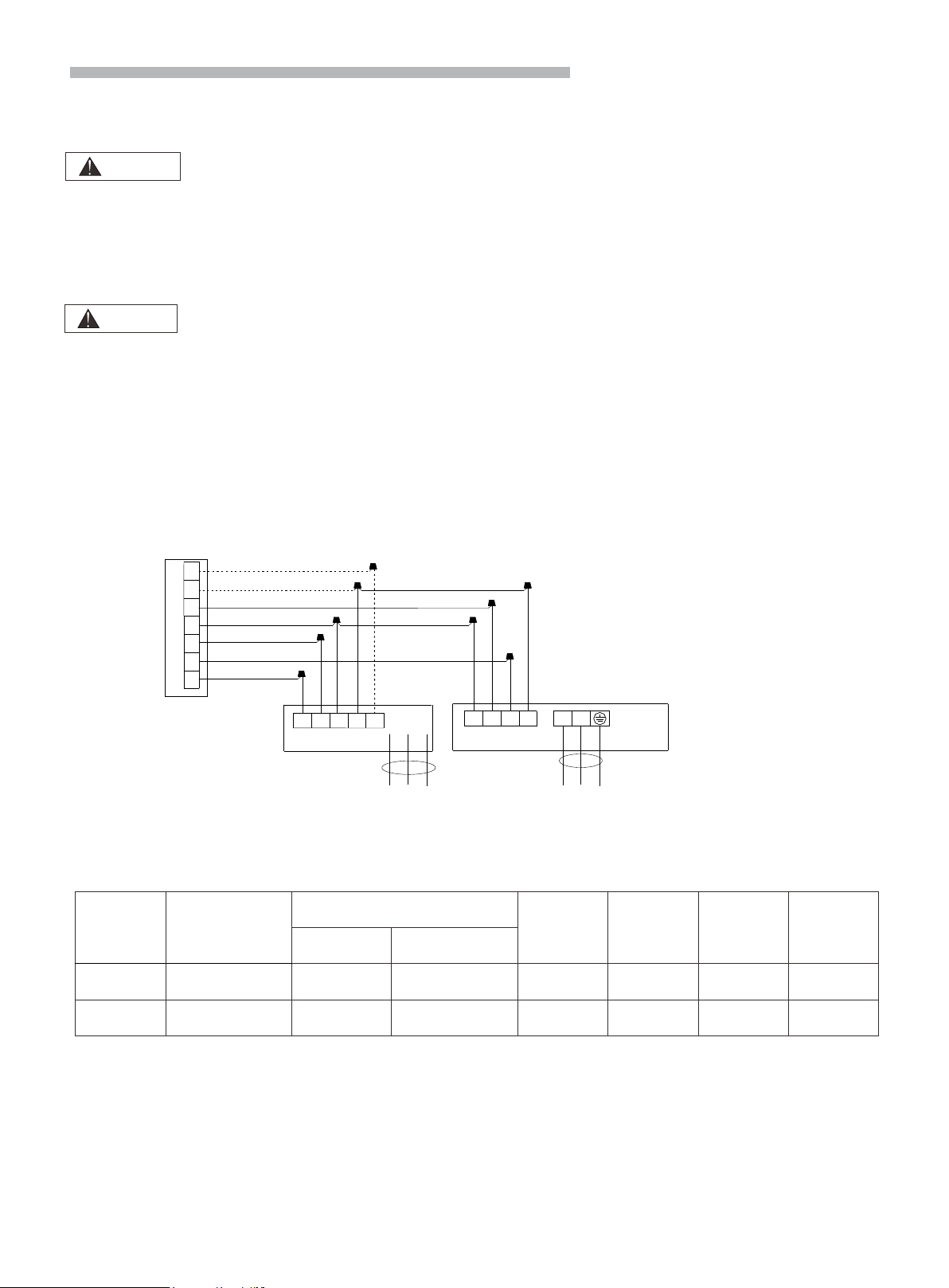
Wiring Diagram
8
L1 L2 PE
Power SupplyPower Supply
Thermostat
Indoor Unit Outdoor Unit
Power
Terminal
Panel
( )
(L2)
(L1)
W1
W2
B
C
R
Y
G
G
R
C
C B Y W
W1
W2
NOTE:
Donotconnect thedashedlinewhenthe electricheaterisnotused.
Wiringmustbeperformedaccordingtowiringdiagrampastedonindoorunit.
Electrical Data
Max. Running Current (A):
REFER TO NAMEPLATE
NOTE:
(1) Follow local codes and regulations when selecting field wires. All the above are the minimum wire sizes.
(2) When transmission cable length is longer than 262ft. (80m), a thicker wire size should be selected.
(3) Install main switch and ELB for each system separately. Select a high-response type ELB that activates within 0.1
second.
(4) If auxiliary heater is required and already installed on indoor unit, power source cable should be installed separately
and the size should be selected in accordance with UL standards.
Model
(Capacity)
Power Supply
ELB
Power
Source
Cable Size
Transmitting
Cable Size
Thermostat
Signal Size
Circuit
Breaker (A)
Rated Current
(A)
Nominal Sensitive
Current (mA)
24K/36K 208/230V ~/60Hz 10 30 3×16AWG 4×16AWG 5×18AWG 10
60K 208/230V ~/60Hz 15 30 3×16AWG 4×16AWG 5×18AWG 15
Loading ...
Loading ...
Loading ...