Maximum inlet supply pressure: 13 in wc (3.24KPa)
Minimum inlet supply pressure: 8 in wc (1.99 KPa)
INSTALLER: Leave this manual with the appliance.
CONSUMER: Retain this manual for future reference.
ANS Z21.97 CSA 2.41-2017
Outdoor Decorative Gas Appliances
01
WARNING: For Outdoor Use Only.
DANGER
FIRE OR EXPLOSION HAZARD
WARNING
Do not store or use gasoline, or other
flammable vapors and liquids,in the
vicinity of this or any other
appliance.
An LP-cylinder not connected for use
shall not be stored in the vicinity of
this or any other appliance.
Installation and service must be
performed by a qualified installer,
service agency, or the gas supplier.
DANGER
CARBON MONOXIDE HAZARD
This appliance can produce carbon monoxide which has no odor.
Using it in an enclosed space can kill you.
Never use this appliance in an enclosed space such as a camper,
tent, car or home.
WARNING:
If the information in this manual is not followed exactly, a fire or explosion may result causing
property damage, personal injury, or loss of life.
If you smell gas:
Shut off gas to the appliance.
Extinguish any open flame.
If odor continues, leave the area immediately.
After leaving the area, call your gas supplier or fire
department.
Failure to follow these instructions could result in
fire or explosion, which could cause property
damage, personal injury, or death.
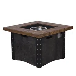
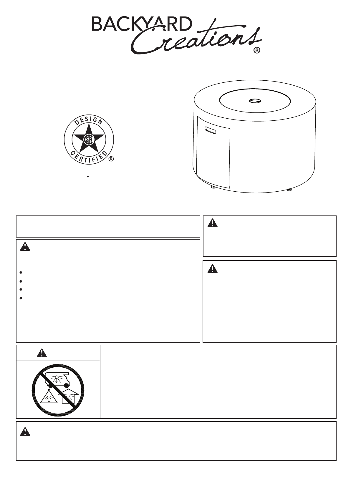
Timbercrest Fire Table
ITM./ART.#: 2595235
MODEL#: F200074-A1

02
IMPORTANT SAFETY INFORMATION
The installation must conform with local codes or, in the absence of local codes, with the National Fuel Gas
Code, ANSI Z223.1
●NFPA 54; National Fuel Gas Code; Natural Gas and Propane Installation Code, CSA
B149.1; or Propane Storage and Handling Code, CSA B149.2, as applicable.
The appliance must be isolated from the gas supply piping system by closing its individual manual shutoff
valve during any pressure testing of the gas supply piping system at test pressures equal to or less than 1/2
psi (3.5 kPa).
The maximum inlet gas supply pressure is 250 psi.
The appliance area must be kept clear and free from combustible materials, gasoline, and other flammable
vapors and liquids.
Do not use this appliance if any part has been under water. Immediately call a qualified service technician to
inspect the appliance and to replace any part of the control system and any gas control that has been under
water.
Children and adults should be alerted to the hazards of high surface temperatures and should stay
away to avoid burns or clothing ignition.
Young children should be carefully supervised when they are in the area of the appliance.
Clothing or other flammable materials should not be hung from the appliance or placed on or near the
appliance.
Any guard or other protective device removed for servicing the appliance shall be replaced prior to
operating the appliance.
Installation and repair should be done by a qualified service person. The appliance should be
inspected before use and at least annually by a qualified service person. More frequent cleaning may
be required as necessary. It is imperative that the control compartment, burners, and circulating air
passageways of the appliance are kept clean.
CAUTION: The propane gas pressure regulator provided with this appliance must be used. This regulator is
set for an outlet pressure of 11 inches water column.
DO NOT burn solid fuels in this appliance.
This outdoor gas appliance is for Outdoor Use ONLY.
This outdoor gas appliance is not intended to be installed in or on recreational vehicles and/or boats.
This outdoor appliance is not for use on wood decks or other flammable surface.
Before each use of this gas appliance, open the door and/or the LP (Liquid Propane) Tank Drawer and inspect
the hose. If there is evidence of excessive abrasion or wear or if the hose is damaged, the hose assembly
must be replaced prior to the appliance being put into operation. Use only the replacement hose assembly
specified in this manual. Make sure to leak test.
Before each use of this gas appliance, inspect the burner. The burner must be replaced prior to the appliance
being put into operation if it is evident that the burner is damaged. Use only the replacement burner specified
in this manual.
Make sure to properly locate the gas hose including locating the hose out of pathways where people may trip
over it or in areas where the hose may be subject to accidental damage.
Keep the fuel supply hose away from any heated surface.
Never use this appliance closer than 10 feet from anything flammable, including houses or overhead tree
branches.
Never use gasoline, kerosene, or any other liquid fuel to start a fire.
Always maintain a safe distance from the fire.
Always supervise children around the fire.
Never leave a fire unattended.
The appliance is hot during and after use, always allow ample cooling time before touching or moving.
1.
2.
3.
4.
5.
6.
7.
8.
9.
10.
11.
12.
13.
14.
15.
16.
17.
18.
19.
20.
21.
22.
23.
24.
25.
SPECIFICATIONS
Rated Heat Input (Liquid Propane & Natural Gas) 50,000 BTU/hr
nmuloc retaw sehcni 11 erusserP rotalugeR enaporP
nmuloc retaw sehcni 7 erusserP telnI saG larutaN
Clearance to combustible surfaces Sides: 24in. (610mm), Top: 72in. (1829mm)
03
IMPORTANT SAFETY INFORMATION ABOUT
PROPANE (LP) GAS
The LP-gas supply cylinder to be used must be constructed and marked in accordance with the U.S.
Deparment of Transportation (D.O.T.) Specifications for LP-Gas Cylinders, or the Standard for Cylinders,
Spheres and Tubes for Transportation of Dangerous Goods and Commission, CAN/CSA-B339, as applicable.
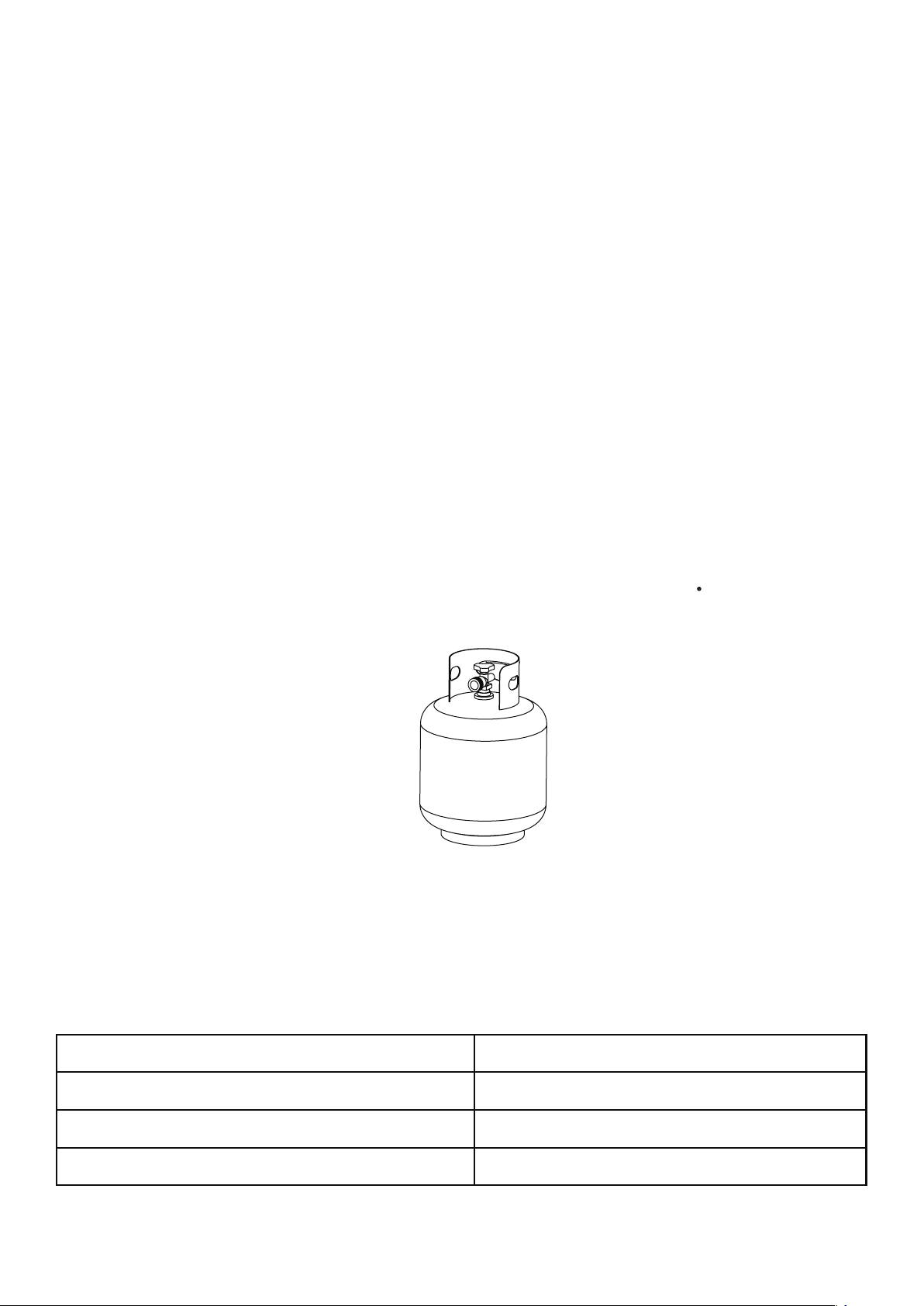
The LP-gas supply cylinder to be used must have a listed overfilling prevention device (See Figure 1).
The LP-gas supply cylinder to be used must have a cylinder connection device compatible with the
connection for the appliance.
A self-contained LP-gas cylinder for use with this appliance must have a capacity of 20 Ibs cylinder (Height
approximately 18 in., Tank Body approximately 12 in. diameter, Base approximately 8 in. diameter).
The cylinder supply system must be arranged for vapor withdrawl.
The cylinder used must include a collar to protect the cylinder valve.
This appliance shall be used only outdoors in a well-ventilated space and shall not be used in a building,
garage or any other enclosed space.
When this appliance is not in use, the gas must be turned off at the supply cylinder.
Storage of this appliance indoors is permissible only if the cylinder is disconnected and removed from the
appliance.
Cylinders must be stored outdoors in a well-ventilated area out of the reach of children.Disconnected
cylinders must have threaded valve plugs tightly installed and must not be stored in a building, garage or
anyother enclosed areas.
This appliance is certified by CSA (Canadian Standards Association) to ANS Z21.97 CSA 2.41-2017,
Outdoor Decorative Gas Appliances.
1.
2.
3.
4.
5.
6.
7.
8.
9.
10.
11.
Standard 20 Ib.tank
Figure 1
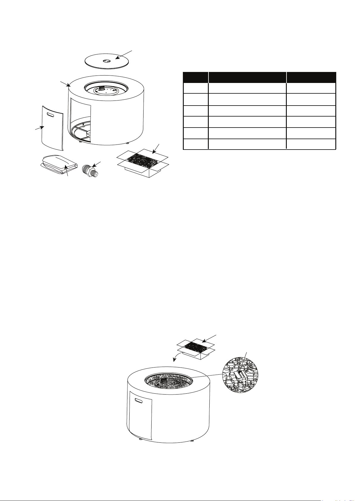
Figure 2
F
E
04
ASSEMBLY INSTRUCTIONS
1.
2.
Carefully unpack all parts from the box, compare parts with package content listed above, make sure all parts
are present before beginning assembly of product. If any part is missing or damaged, do not attempt to
assemble the product. Contact customer service for replacement parts.
Place the lava rocks (F) around the burner (See Figure 2). A gas fire pit requires 13.2 lbs lava rocks.
WARNING: keep children away during assembly, as this item contains lava rocks, which are small pieces and
can be swallowed by children.
NOTE: leave the pilot box uncovered by the lava rocks.
CAUTION: this fire pit is equipped with natural lava rock that may crackle or pop the first time it is used. Lava
rock has been pre-heat treated. How ever, in rare cases on first time use, lava rock may pop or burst causing
small pieces of hot rock to fly out of the fire pit. These hot pieces could strike somebody's face during the
process of lighting the fire pit, stay away from the fire pit for the first 20 minutes after igniting.
PART DESCRIPTION QUANTITY
A
1 pc
B
1 pc
C
1 pc
1 pc
D
1 pc
Lid
Fire Table
Door
Lava rock (13.2 Ibs)
Natural gas orifice
Weather cover
PACKAGE CONTENTS
1 box
C
A
D
B
F
F
pilot box
E
05
Figure 7
4.
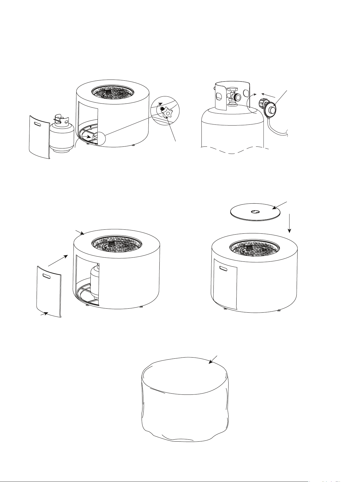
Attach the door (B) to fire table (A) tenderly (See Figure 5). Place the Lid (C) onto the fire bowl when not
in use to protect it from the elements or when fire pit is cool COMPLETELY after the use (See Figure 6).
5. Cover the fire pit with the outdoor Weather cover (D) when not in use to protect it from the elements or when
fire pit is cool COMPLETELY after the use (See Figure 7).
3.Place the gas cylinder into the cylinder holder. Secure the cylinder by tightening clockwise the retention
point found on the cylinder holder (See Figure 3), so that the cylinder cannot move from side to side or fall
down. Connect the regulator, screw the black handle clockwise to tighten (See Figure 4), turn the black
handle counterclockwise to remove. The hose must point down. The knob on the control panel is turned all
the way to the “OFF” position when the fire pit is NOT in use.
Figure 3
Figure 4
A
B
C
Figure 5 Figure 6
D
black handle
retention point
06
Natural gas conversion must be performed only by natural gas provider or service company.
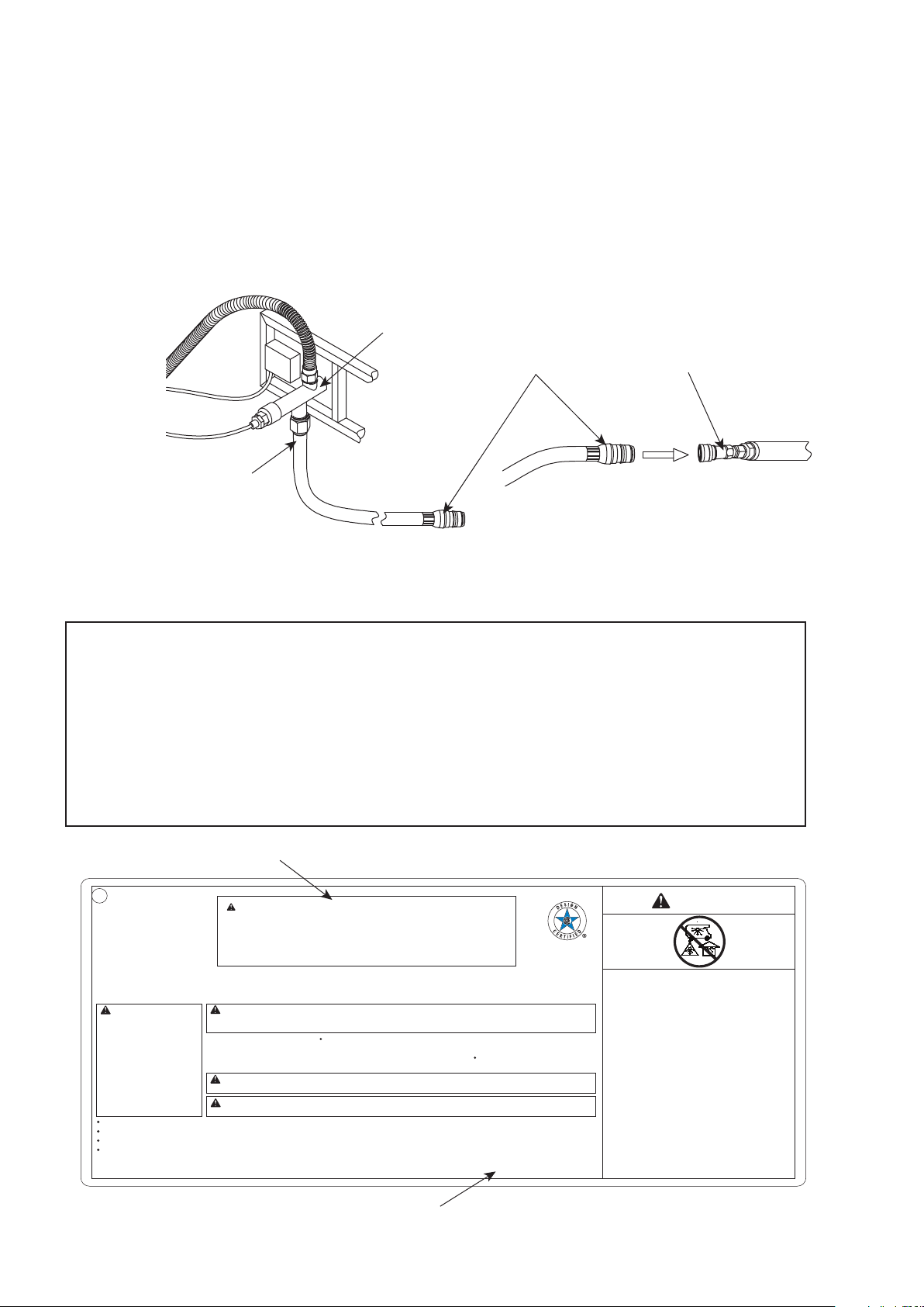
1. Disconnect the propane hose from the gas valve (See Figure 8).
Caution: The gas supply shall be shut off prior to disconnecting the electrical power, before proceeding with
the conversion.
2. Unscrew and disconnect the propane orifice from the bellows (See Figure 9). Propane orifice (dia2.21mm
size) is painted with red mark.
Figure 9
Figure 8
NATURAL GAS CONVERSION
STOP
STOP
3. Replace the propane orifice with the natural gas orifice, screw the natural gas orifice with the bellows tightly,
then connect and tighten the natural gas orifice with inlet tube (See Figure 10). Natural gas orifice (E)
(dia 4.18mm size) is painted with black mark.
Figure 10
gas valve
propane hose
propane orifice
bellows
propane orifice
bellows
inlet tube
bellows
natural gas orifice (E)
5. Stick and cover the conversion label onto the propane rating plate (See Figure 13).
WARNING: If the information in this manual is not followed exactly, a fire or explosion may result causing
property damage, personal injury, or loss of life.
WARNING: Improper
installation, adjustment,
alteration, service or
maintenance can cause
property damage, personal
injury or loss life. Refer to the
owner's information manual
provided with this appliance.
Installation and service must
be performed by a qulified
installer, service agency, or
the gas supplier.
Item Number:
Model No:
Serial No:
Date Code:
DANGER
CARBON MONOXIDE
HAZARD
This appliance can
produce carbon
monoxide which has no
odor. Using it in an
enclosed space can kill
you. Never use this
appliance in an enclosed
space such as a camper,
tent, car or home.
WARNING:
WARNING: Placing the cylinder too close to the appliance might cause the fire hazard or property loss or
even life hazard.
Type of gas: propane
Normal Hourly lnput: 30,000BTU/hr (8.79 kW)
Manifold Pressure: 11 inch w.c. (2.74 kPa)
Maximum inlet supply pressure: 13 inch w.c. (3.24 kPa)
Minimum inlet supply pressure: 8 inch w.c. (1.99 kPa)
CAUTION: The gas pressure regulator provided with this appliance must be used.
This regulator is set for an outlet pressure of 11 inches water column.
Minimum clearance from combustible constructions: Sides:24in. 610mm. Top:72in. 1829mm.
For Outdoor Use Only. If Stored Indoors, Detach and Leave Cylinder Outdoors.
The gas supply must be turned off at the LP-gas supply cylinder when this appliance is not in use.
Complies with ANS Z21.97-2017 CSA 2.41-2017, Outdoor Decorative Gas Appliance Standards.
Cover must be removed when burner is in operation.
Removal of this marking will void compliance with standard ANS Z21.97-2017 CSA 2.41-2017.
Do not connect to a remote gas supply.
The instruction manual contains important information necessary for the proper assembly and safe use of the appliance.
Read and follow all warnings and instructions before assembling and using the appliance.
Follow all warnings and instructions when using the appliance.
If instructions or parts are missing. contact Foremost TOLL FREE# 1-855-390-5474 or 1-800-443-1410 (USA) or 001-855-286-4931 (Int)
between the hours of 8:30 am and 5:00 pm EST, Monday through Friday or fax your request to (973) 428-8026 or email us at
customerservice@foremostgroups.com
Foremost Groups, Inc.
906 Murray Road,
East Hanover, NJ 07936, U.S.A.
Do not store or use gasoline, or other flammable vapors and liquids, in the vicinity of this or any other appliance.
An LP-cylinder not connected for use shall not be stored in the vicinity of this or any other appliance.
CAUTION: This appliance has been converted to use natural gas.
Propane orifice dia 2.21 mm, natural gas orifice dia 4.18 mm.
Rated Heat Input: 50,000BTU/hr (14.65 kW)
Type Gas: Natural gas
Max Gas Supply Pressure: 7 inches water column (1.74 kPa)
Min. Gas Supply Pressure: 5 inches water column (1.24 kPa)
conversion label
propane rating plate
07
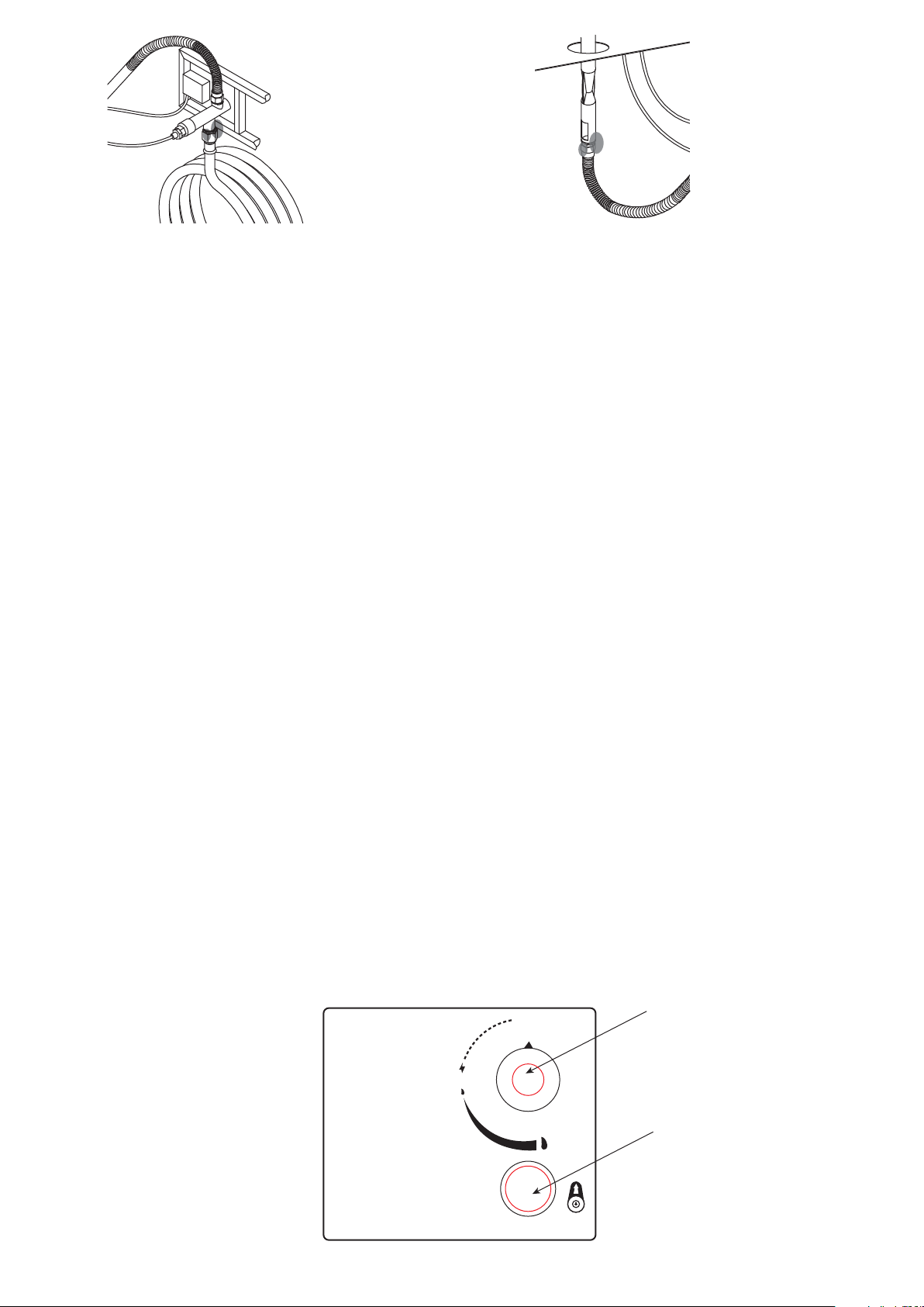
gas valve
natural gas hose
natural gas fixture
natural gas supply
piping system
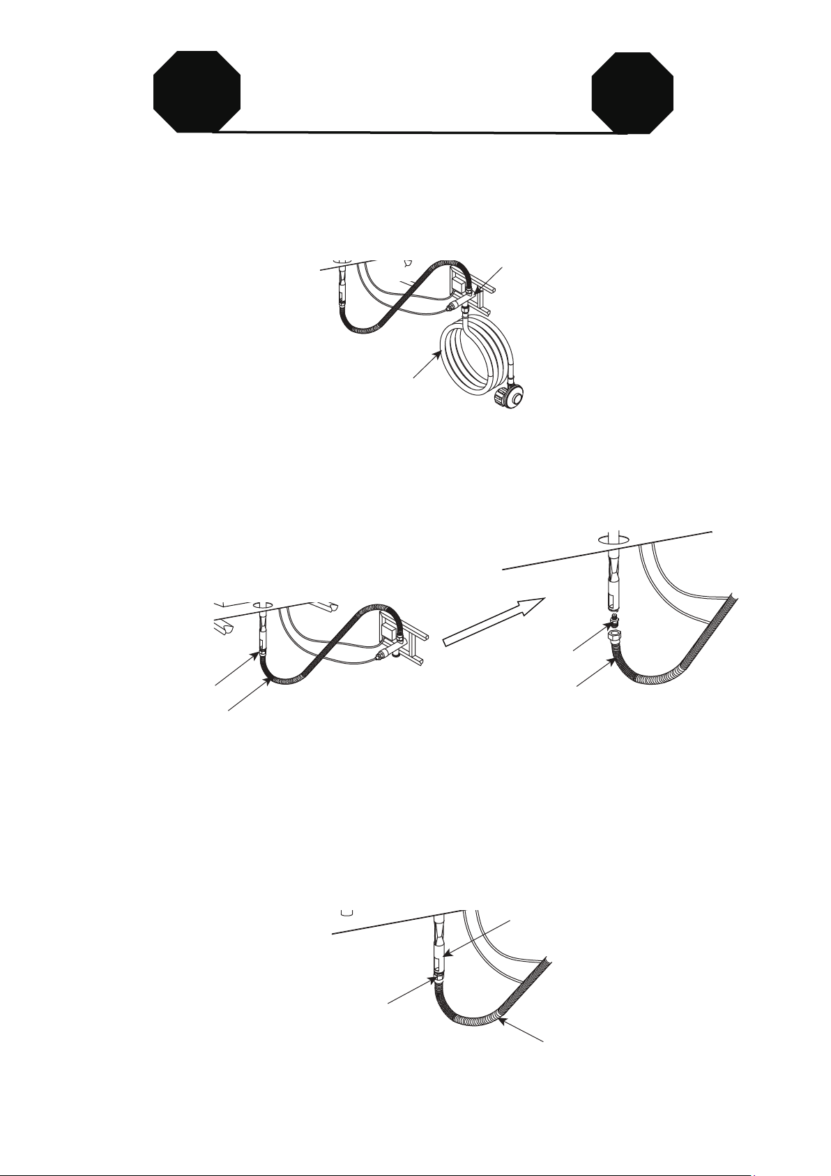
4. Connect the natural gas hose with the gas valve by screwing clockwise tightly (See Figure 11). Plug the
natural gas fixture into the natrual gas supply piping system (See Figure 12).
Conversion kit should be CSA certified and purchased from the market, the conversion kit hose
connector and quick disconnect listed as below.
(1). Part# DH22 / QH1, manufacturer: KSUN
or (2). Part# WH02 / KJ50A2, manufacturer: Laite
or (3). Part# KJ-3/8G-3/8 / KJ-3/8G, manufacturer: Wanan
The natural gas orifice is included in the package. Please follow the instructions for gas conversion.
Figure 13
Figure 11 Figure 12
WARNING: This conversion kit shall be installed by a qualified service agency in
accordance with the manufacturer’s intructions and all applicable codes and requirements
of the Authority Having Jurisdiction. If the information in these instructions is not followed
exactly, a fire, explosion or production of carbon monoxide may result causing property
damage, personal injury or loss of life. The qualified service agency is responsible for the
proper installation of this kit. The installation is not proper and complete until the operation
of the converted appliance is checked as specified in the manufacturer’s instructions
supplied with the kit.
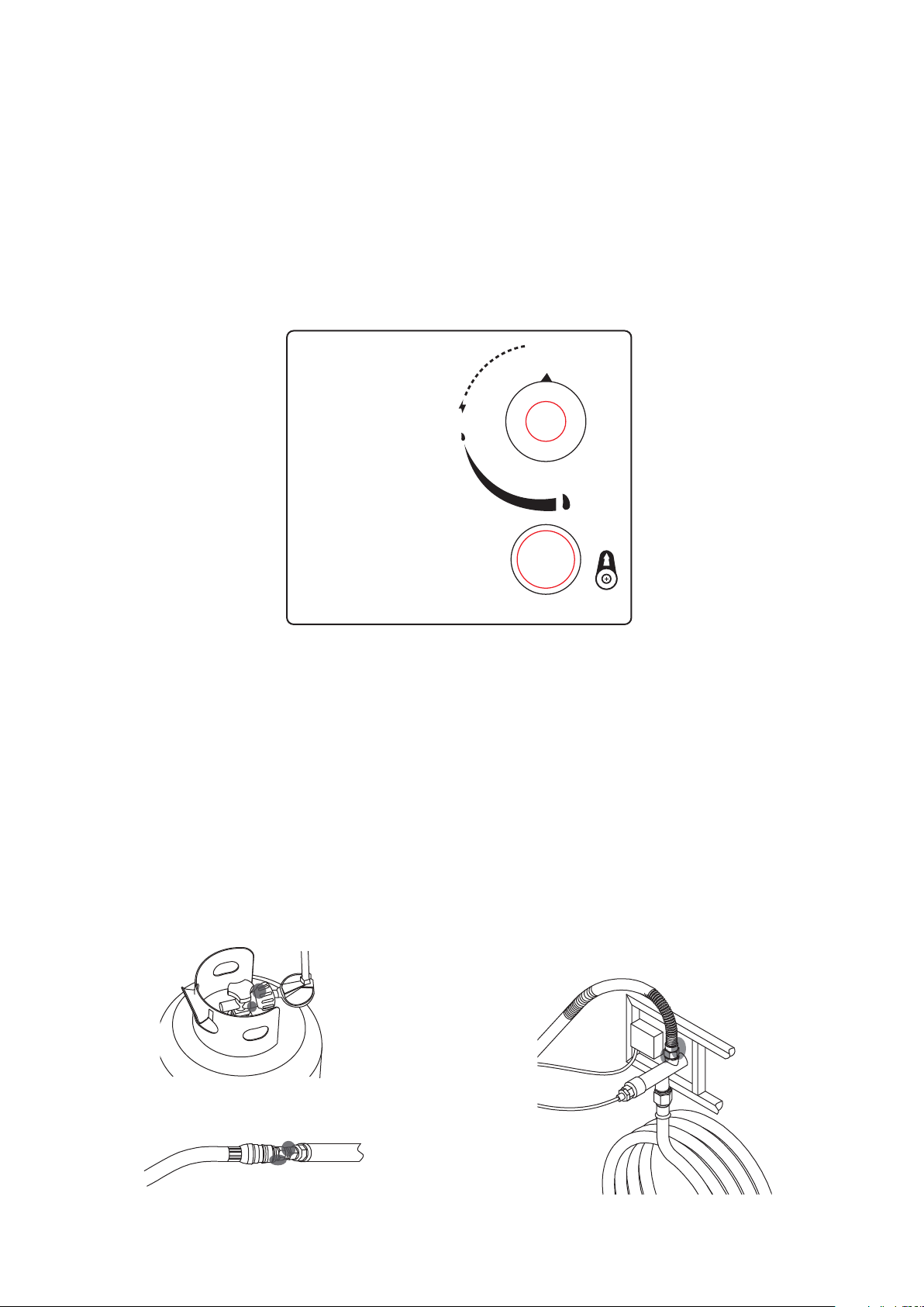
Figure 14
BATTERY
BATTERY
WARNING:
Make sure the control knob is in the “OFF” position. Unscrew the push button cap on the ignitor module located
on the control panel to access the battery compartment. The ignitor module requires one AAA size battery (See
Figure 14),
BATTERY IS NOT INCLUDED.
1. Please observe proper polarity and use the correct battery type when placing or replacing the battery.
Improper installation could result in ignition failure.
2. Please remove the battery if consumed or if product is to be left unused for a long period of time.
1. Always perform the leak test as described below before lighting this appliance or each time the
cylinder is connected for use.
2. Do not smoke or allow other sources of ignition in the area while conducting a leak test.
3. Conduct the leak test outdoors in a well-ventilated area.
4. Do not use matches, lighters or a flame to check for leaks.
5. Do not use this appliance until any and all leaks are corrected. If you are unable to stop a leak,
disconnect the propane supply. Call a gas appliance service shop or your local propane gas supplier.
To prevent fire or explosion hazard when testing for a leak:
cylinder-regulator connection (Figure 15)
natural gas fixture-natural gas supply
piping system connection (Figure 16)
gas valve-bellows connection (Figure 17)
OFF
(APG.)
MAX
(MÁX.)
1 AAA
1.5V
IGNITOR
( Encendedor )
ON/MIN
(ENC./MÍN.)
LIGHTING INSTRUCTIONS
1. Push in gas control knob slightly and
2. Turn gas control knob to “ON/MIN”.
3. Push in gas control knob all the way
4. If the burner does not light in 15
1. Push in gas control knob slightly and turn to “OFF”.
TO TURN OFF GAS
INSTRUCCIONES DE ENCENDIDO
PARA CERRAR EL GAS
1. Presione ligeramente la perilla de control del gas y gírela a la
2. Gire la perilla de control del gas a “ENC/MÍN” (encendido/mínimo).
3. Presione la perilla de control del gas hasta el fondo y mantenga presionada.
4. Si el quemador no se enciende en 15 segundos, suelte la perilla y esta
encender el quemador nuevamente, repita los pasos 1 al 3.
1. Presione ligeramente la perilla de control del gas y gírela a la
turn to “OFF”.
and hold. Continue to press the
ignition button for 15 seconds.
seconds, release the knob and it will
pop back out. Wait 5 minutes before attempting
to light the burner again, repeat step 1 to 3.
posición “APG” (apagado).
Siga presionando el botón de encendido durante 15 segundos.
volverá a su posición hacia afuera. Espere 5 minutos antes de intentar
posición “APG” (apagado)
08
09
LIGHTING INSTRUCTIONS
Make 2~3 oz. of leak solution by mixing one part liquid dishwashing detergent and three parts water.
NOTE: make sure control knob is “OFF”.
Apply several drops of solution where the cylinder attaches to regulator (See Figure 15), inspect the solution
at the connection looking for bubbles. If NO bubbles appear, the connection is secure. If bubbles appear, the
connection has the leak, disconnect the regulator, reconnect, perform another leak check. If you continue to
see bubbles after several attempts, cylinder valve is defective and should be returned to cylinder’s supplier.
Apply several drops of solution where natural gas fixture attaches to natural gas supply piping system
connection (See Figure 16), If NO bubbles appear, the connections are secure. If bubbles appear, the
connection has the leak, disconnect, reconnect,perform another leak check. If you continue to see bubbles
after several attempts, the part is defective and should replace the part.
Apply several drops of solution where gas valve attaches to bellows (See Figure 17), where gas valve
attaches to hose (See Figure 18), and where inlet tube attaches to bellows (See Figure 19). If NO bubbles
appear, the connections are secure. If bubbles appear, the connection has the leak, disconnect,
reconnect,perform another leak check. If you continue to see bubbles after several attempts, the part is
defective and should replace the part.
1. Push in gas control knob slightly and turn to “OFF”.
2. Turn gas control knob to “ON/MIN”.
3. Push in gas control knob all the way and hold. ontinue to press the ignition button for 15 seconds.
4. If the burner does not light in 15 seconds, release the knob and it will pop back out. Wait 5 minutes before
attempting to light the burner again, repeat step 1 to 3.
WARNING: For your safety, read and follow the Lighting Instructions in this manual and in the Rating Plate
on the appliance. IMPROPER LIGHTING PROCEDURES COULD RESULT IN A FIRE HAZARD OR
EXPLOSION HAZARD OR PROPERTY DAMAGE, INJURY OR LOSS OF LIFE.
TO TURN OFF GAS
1. Push in gas control knob slightly and turn to “OFF”.
To perform a leak test:
gas valve-hose connection (Figure 18) inlet tube-bellows connection (Figure 19)
Figure 20
1.
2.
3.
4.
gas control knob
ignition button
OFF
(APG.)
MAX
(MÁX.)
1 AAA
1.5V
IGNITOR
( Encendedor )
ON/MIN
(ENC./MÍN.)
LIGHTING INSTRUCTIONS
1. Push in gas control knob slightly and
2. Turn gas control knob to “ON/MIN”.
3. Push in gas control knob all the way
4. If the burner does not light in 15
1. Push in gas control knob slightly and turn to “OFF”.
TO TURN OFF GAS
INSTRUCCIONES DE ENCENDIDO
PARA CERRAR EL GAS
1. Presione ligeramente la perilla de control del gas y gírela a la
2. Gire la perilla de control del gas a “ENC/MÍN” (encendido/mínimo).
3. Presione la perilla de control del gas hasta el fondo y mantenga presionada.
4. Si el quemador no se enciende en 15 segundos, suelte la perilla y esta
encender el quemador nuevamente, repita los pasos 1 al 3.
1. Presione ligeramente la perilla de control del gas y gírela a la
turn to “OFF”.
and hold. Continue to press the
ignition button for 15 seconds.
seconds, release the knob and it will
pop back out. Wait 5 minutes before attempting
to light the burner again, repeat step 1 to 3.
posición “APG” (apagado).
Siga presionando el botón de encendido durante 15 segundos.
volverá a su posición hacia afuera. Espere 5 minutos antes de intentar
posición “APG” (apagado)
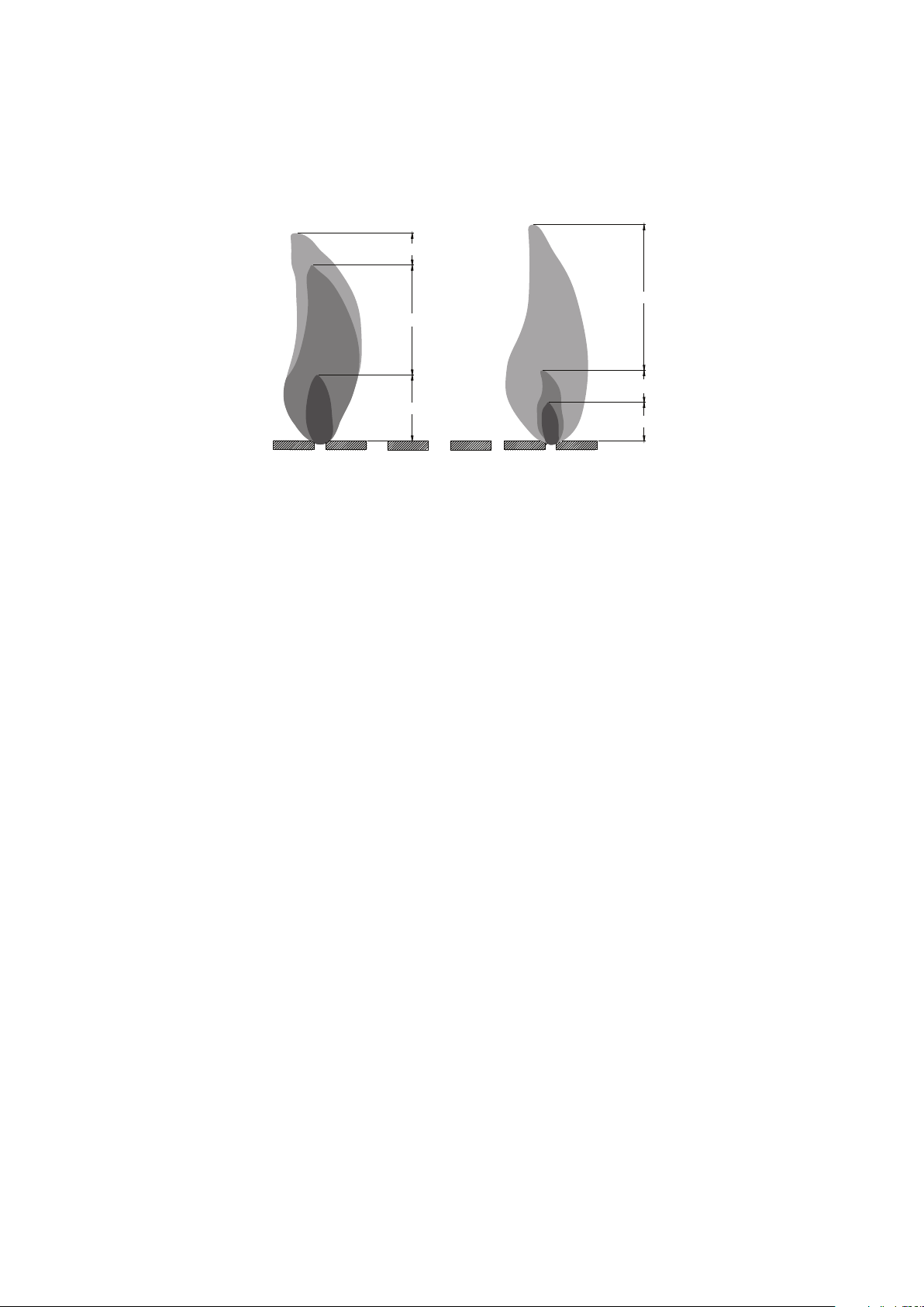
Observe Flame Height When Lit: The burner will display blue and yellow flames. These flames should be
a blue / yellow color between 1~2 in. height (See Figure 21). These flames should not be yellow or produce
thick smoke. This would indicate an obstruction of airflow through the burners. The flames should be blue
with straight yellow tops.
Figure 21
CARE AND MAINTENANCE
Yellow
Yellow
Light Blue
Light Blue
Blue
Blue
Good Bad
To enjoy the outstanding performance from your fire pit, make sure you perform the following activities on a
regular basis:
1. Use warm soapy water for cleaning. Never use flammable or corrosive cleaning agents.
2. While cleaning the fire pit, make sure to keep the area around the burner dry at all times. DO NOT
submerge the control valve assembly. If the gas control is submerge in water, DO NOT use it. It must
be replaced.
3. Air flow must be unobstructed. Keep controls, burner, and circulating air passageways clean. Signs of
possible blockage include:
(1). Gas odor with extreme yellow tipping of flame.
(2). Fire pit does NOT reach the desired temperature.
(3). Fire pit flame is excessively uneven.
(4). Fire pit makes popping noises.
(5). Spiders and insects can nest in burner or orifice. This dangerous condition can damage fire pit and
render it unsafe for use. Clean burner holes by using a heavy-duty pipe clearer. Compressed air
may help clear away small particles.
4. Carbon deposits may create a fire hazard. Clean burner with warm soapy water if any carbon deposits
develop.
5. Cover your fire pit with an outdoor weather cover when not in use to protect it from the elements.
NOTE: Always allow fire pit to cool COMPLETELY before you cover the fire pit with an outdoor weather
cover or you attempt the service or maintenance.
10

11
REPLACEMENT PARTS LIST
NOITPIRCSED #TRAP ON
1
2
3
4
5
6
F200074-A
F200074-B
F200074-C
F200074-D
F200074-E
F200074-F
7
F200074-G
9
8
F200074-I
F200074-H
Door
Lava rocks
Thermocouple
Hose assembly
Fire table assembly
Lid
Natural gas orifice
Weather cover
Foot glider

12
WARRANTY
Firepits
Burner, steel fire pit bowl, all mechanical parts and fittings to control panel and burner assembly, and all fire pit
tops that are not cast aluminum are warranted for a period of one (1) year from original date of purchase,
against defects in material and or workmanship. Rust is not covered.
Frames
Frames are warranted to be free from defects in materials and workmanship for a period of one (1) year.
Damage to frames or welds due to improper assembly or exposure to water and sub-freezing temperatures, is
not covered. Breakage that is a result of product being dropped, acts of God, acts of war, etc. are not covered.
Finish
The finish is warranted against peeling, cracking, or blistering for a period of one (1) year provided the product
has not been scratched or abraded. Scratches and chips resulting from normal wear and tear are not covered.
Fading resulting from exposure to elements is not covered. Stains as a result of chemical spills and certain
food items are not covered.
Table Tops
All table tops are warranted for a period of one (1) year from original date of purchase, against defects in
material and or workmanship. Breakage, discoloration, staining, and or any other weather related issues are
not covered.
To obtain warranty service please contact Foremost Groups Customer Relations Department email us at
Warranty Exclusions
Failure caused by unreasonable or abusive use. Firepits that were clearance items, display models or items
purchased in an "as is" condition, freight damage, firepit damaged by acts of nature, vandalism, fire, abuse, lack
of proper care and maintenance, or improper assembly; straps and normal fading or discoloration from exposure
to elements, oils, spills, fluids or chemicals; Table top against breakage; hardware against corrosion or rusting;
buckling or splitting of tubing resulting from exposure to water and freezing temperatures; glass table tops,
purchased or replacement parts; plastics. Also excluded: loss of use of time and or inconvenience, money,
travel, packaging or any other consequential or incidental damages. In no event shall Foremost Groups Inc.
responsibility exceed the value of the replacement product. Warranty is to the original purchaser when items are
purchased from one of our authorized retailers and is not transferable. All warranty claims must be submitted
with a dated register receipt within the warranty period. Should replacement of the warranted item be
unavailable, Foremost Groups Inc. reserves the right to substitute items of our choice similar in style, color and
quality. For quality control purposes and verification, we reserve the right to request photographs of the damage
item(s). The terms of this warranty are subject to change without notice.