Loading ...
Loading ...
Loading ...
8
www.waynepumps.com
Operating Instructions and Parts Manual
INSTALLATION (CONTINUED)
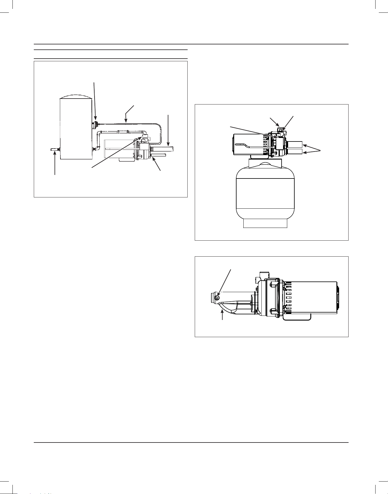
Figure 6 - Vertical Tank
OUTLET
AIR VOLUME
CONTROL
TUBING
PRIMING PLUG
SUCTION
AIR VOLUME CONTROL
DRIVE
DEEP WELL PUMP WITH PRE-CHARGED STORAGE TANK
(FIGURE 7)
1. Check tank pre-charge using a tire pressure gauge. Set air pressure
in tank to 28 psi which is 2 psi below pressure switch cut-in level. An
air valve is located on the side and will accept a standard fitting from
a bicycle pump or air line.
2. Check the pressure with the power off, faucets open and no water
flowing (zero water pressure).
3. Install a valve and isolator hose between the system and the house
plumbing to aid in pump removal for servicing and for reducing noise
transmitted to the house through the piping.
4. Provide a faucet at the lowest point in the system to drain for service
or storage.
CONVERTING THE DEEP WELL PUMP TO SHALLOW WELL
OPERATION (FIGURE 8)
For shallow wells (25 feet or less), a bolt-on shallow well jet is available as
an accessory for deep well pumps. The jet attaches to the front of the
pump with the two bolts provided and converts the deep well pump into
a shallow well pump. The shallow well jet has a 1 in. NPT inlet and a 1/8
in. NPT opening for an air volume control. For optimum performance, an
inline check valve on the inlet side of the shallow well jet is recommended.
Figure 7 - Pre-charged Storage Tank
OUTLET
PRIME PLUG
TO JET
ASSEMBLY
PRESSURE
SWITCH
Figure 8 - Shallow Well Jet
TO AIR VOLUME CONTROL
JET ASSEMBLY
Loading ...
Loading ...
Loading ...