Loading ...
Loading ...
Loading ...
7
www.waynepumps.com
CWS Series
INSTALLATION (CONTINUED)
5. Slope the horizontal pipes upward toward the pump to prevent
trapping air. If horizontal distance exceeds 25 feet, see Chart 1 for
recommended pipe sizes.
DRILLED WELL (2 IN.) WITH SINGLE PIPE PACKER (FIGURES 16
AND 4)
NOTE: Single pipe packer jets rely on the space between single pipe and
inside of well casing for return water to operate jet. Two inch installations
must use 1-1/4 in. galvanized steel pipe with special turned couplings (1-
13/16 in. O.D.) to avoid restricting flow of return water back to jet.
1. Assemble the foot valve and packer to the jet body.
2. Lubricate the rubber cups with petroleum jelly.
3. Attach the first section of pipe and lower jet into well.
4. Add pipe until the jet is positioned 5 - 15 feet below the lowest
anticipated water level. The jet should never be closer than 5 feet
from the bottom of the well or sand and sediment may be drawn
into the system.
5. With the jet in position, fill the pipes with water to make sure the
rubber cups are sealed against inside of the well casing. It may be
necessary to move the jet up and down to seat the cups.
6. Install the casing adapter and the horizontal pipes.
7. Slope both pipes upward toward the pump to eliminate trapping air.
If the horizontal distance exceeds 25 feet, see Chart 1 below, for the
recommended pipe sizes.
CHART 1 - PIPE SIZING
Pump Model
Pump
Opening
Horizontal Distance
(Feet)
0-25 26-100
Deep Well Inlet: Suction 1-1/4 in. 1-1/2 in.
Inlet: Drive 1 in. 1-1/4 in.
Outlet 3/4 in. 1 in.
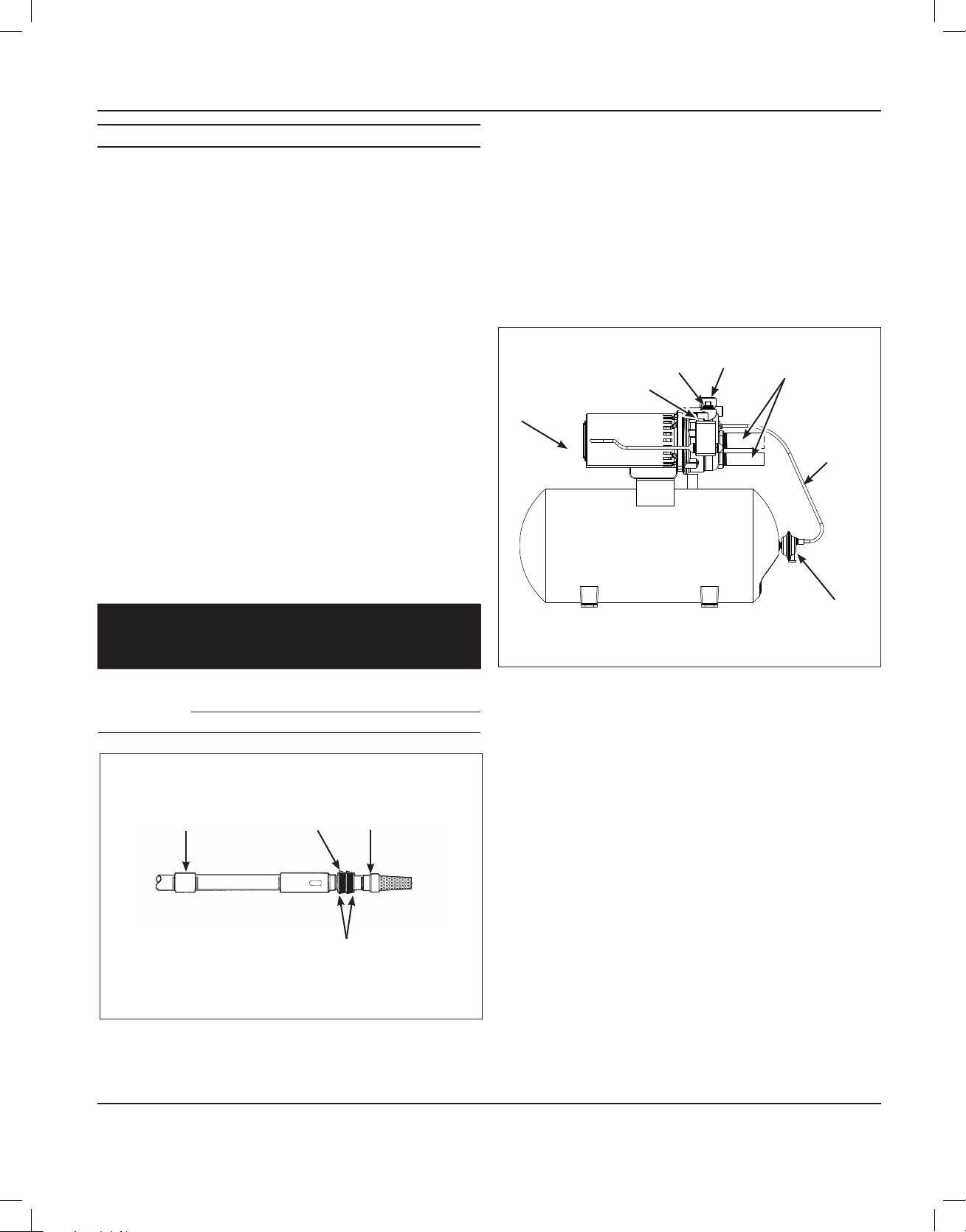
DEEP WELL PUMP WITH HORIZONTAL AND VERTICAL
STORAGE TANK (FIGURES 5 AND 6)
1. Install the air volume control on the tank as shown.
2. Connect the copper tube from the air volume control to the 1/8 in.
NPT opening directly above the 1-1/4 in. opening on the front of the
pump.
3. Install a valve and isolating hose between the system and the house
plumbing to aid in pump removal for servicing and for reducing noise
transmitted through the house piping.
4. Provide a faucet at the lowest point in the system to drain for service
or storage.
Figure 5 - Horizontal Tank
AIR
VOLUME
CONTROL
TUBING
OUTLET
AIR
VOLUME
CONTROL
PRESSURE SWITCH
PRIME PLUG
TO JET
ASSEMBLY
CONVENTIONAL TANK
PUMP
1-1/4 IN. PIPE
Figure 4 - Single Pipe Jet (2” Casing)
PACKER
FOOT VALVE
CUPS
Loading ...
Loading ...
Loading ...