Loading ...
• Bang a trowel on the mat or heating wire to re-
move excess mortar from it.
• Attempt to repair the heating Peel and Heat
Complete if it is damaged. Call Protecto Wrap
Company for instruction before proceeding.
• Install one mat on top of another or overlap
the mat on itself. This will cause dangerous
overheating.
• Forget to install the floor sensor.
• Install Peel and Heat Complete in any walls.
• Install mats under cabinets or other built-ins.
Excessive heat will build up in these small
spaces, and the mat can be damaged by fasteners
(nails, screws, etc.) used to install built-ins.
• Install under nail down wood flooring.
• Remove the nameplate label from the power
leads.
• Allow solvent based products such as sealers or
sealants (including silicone) to come in contact
with the membrane.
ALWAYS:
• Completely embed the heating mats and factory
c
onnection in mortar (tile and stone) or self-leveling
underlayment (laminate and non-masonry) materials.
• Enter mat and sensor readings in the mat and
Sensor Resistance Log (This can be found on the
last Page in the Warranty Information & Regis-
tration Form) before, during, and after the instal-
lation process.
• Refer to the TCNA Handbook recommenda-
tions and ANSI references for proper substrate
needed for thin-set tile installations.
NOTE: Do not apply mats to floors where hydrostatic
o
r moisture vapor rate emissions exist above 4 lbs per
1,000 sq in 24 hours per the Calcium Chloride test
method.
The primary components of the Peel and Heat
Complete System, depending on the project re-
quirements, are:
• Peel and Heat Complete Mat(s);
• Floor-sensing thermostat (programmable or
non-programmable); UL Listed thermostat or
other appropriate control rated for at least 25%
greater capacity than the installed heating load.
Low voltage units may be used in combination
with appropriate relay.
• GFCI Breaker (if not part of the thermostat)
• Protecto Wrap #6000 Water-based Primer.
Other items needed:
• Conduit and Junction boxes Two boxes re-
quired for each room or area. One box (2x4 inch)
required for thermostat; one box (4x4 inch) re-
quired for electrical connections.
• 14-gauge electrical wiring; Digital Ohm Meter
(multi-meter);
• Tile installation products (mortar, backer board,
tile, etc);
• 3/8" x 1/4" or greater trowel and other tile tools;
Various electrical and construction tools (wire
stripper, screw driver, chisel, scissors, etc).
System Warning Labels: These labels are an in-
tegral part of this heating system and must be in-
stalled for the warranty to be in force.
Throughout the installation process, it is very
important to take resistance readings of the mat and
the floor sensor wire to make sure they have not been
damaged. Use a quality, high impedance digital
ohmmeter (multimeter) able to measure to 20,000
ohms (W) to take these readings. Analog meters
(with the moving needle) are not accurate enough
for this product.
When the heating mats are removed from the
shipping box test the resistance and record
the information. if resistance reading varies by
more than 10 ohm’s above the Factory reading
recorded on mat or 5 ohm’s below, do not install
the mat and call Protecto Wrap Company at (800)
759-9727 for replacement assistance.
At the very least, take resistance readings (1)
before beginning the installation, (2) after the
mat and sensor are fastened to the floor, and
(3) after floor coverings are installed. It is highly
r
ecommended that these measurements also
be checked frequently during tile installation
to avoid burying a damaged heating mat or
defective sensor.
Essential Product and
Warranty Information
Do not remove the nameplate label from the
power leads. Record the mat serial number, mat
size, voltage, and resistance range printed on this
label into the resistance log below for each mat
and sensor. To retain the Limited Warranty, these
items and the following measurements must be
recorded, as well as all steps of this manual fol-
lowed. Refer to the Limited Warranty now for
complete requirements.
Positioning of Thermostat
1. Location of the thermostat should be approxi-
mately 60" (120 cm) above the floor on an inside
wall, near the center of the room to allow the con-
nection leads to reach. A 3" deep box is recom-
mended for the thermostat.
Installations with multiple heating mats will re-
quire a junction box to gang the connections to-
gether. If a junction box is required, it should be
located directly beneath the thermostat, 12" to
18" above the floor.
Thermostat Requirements: Thermostat comes
complete with a GFCI (ground fault circuit inter-
rupter) that meets the Electrical Code(s). Ther-
mostats are rated at 1,800 watts, 120 volts or
3,600 watts, 240 volts.
If not using the Protecto Wrap-supplied thermo-
stat, user must purchase a suitably rated UL-
Listed thermostat with GFCI protection.
The total number of mats used in a single circuit
is limited to 15 amps. Use the following table as
a quick reference when specifying only single
voltage/width heating mats. When specifying
multiple width heating mats for the same area,
make sure that the total power required does not
exceed the total power of a single circuit. Add ad-
ditional 20 amp circuits as required for proper
electrical supply to the installation.
Voltage Maximum Total Power
120 1800 watts 15 amps
240 3600 watts 15 amps
12 watts/sq ft X Total Area of Mat(s) = Total Wattage
Step 1: Install GFCI Breaker
(Overcurrent Protection)
Peel and Heat Complete mat must be protected
by a ground fault circuit interrupter (GFCI). This
can be done either by the internal GFCI in the
thermostat (as long as it directly controls the mat)
or an indicating-type GFCI circuit breaker.
Follow all local building and electrical codes.
INSPECTION & TESTING OF HEATING MATS
ELECTRICAL
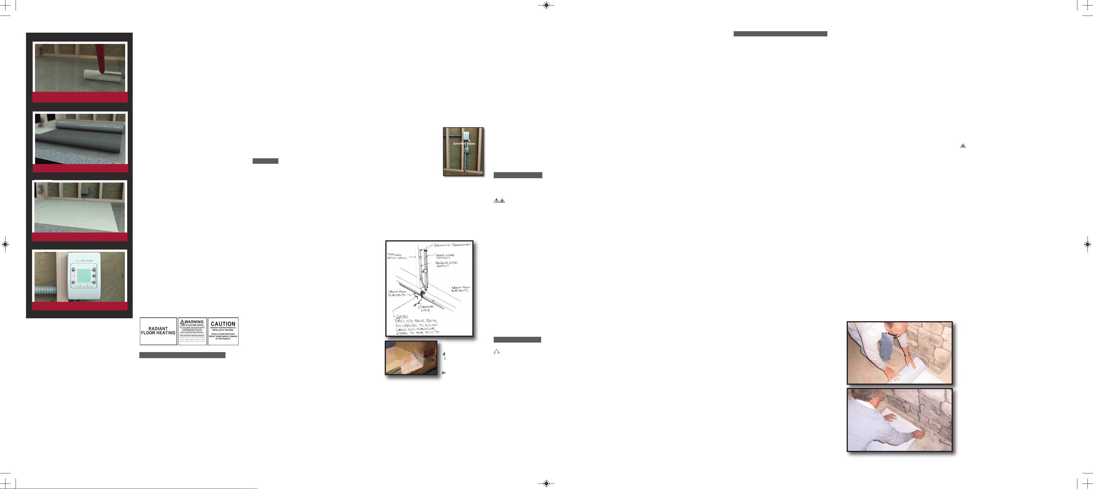
Roll on Protecto Wrap #6000 Primer,
allow 20-30 minutes to dry.
Apply Peel and Heat Complete
1
2
3
Peel and Heat Complete is wired to a junction box.
Programmable thermostat with built-in GFCI
S
tep 2: Install Secondary Slave Unit
(Thermostat Relay)
Depending on the amperage requirements of the
mat(s), a secondary slave unit (Thermostat Relay)
may be required. Do not load the Thermostat con-
trol with more than 15 amps. Be sure to protect this
contactor circuit with a GFCI breaker.
The National Electrical Code specifies that each
branch circuit used in conjunction with a heating
system must be for the exclusive use of the heating
system. Do not connect lights, outlets, etc. to any
branch circuit used with the Peel and Heat Com-
plete System.
Step 3: Install Electrical Boxes
Thermostats are usually lo-
cated near the power leads.
However, they can be lo-
cated almost anywhere, be-
cause the power leads and
the sensor wire can be
routed to electrical junction
boxes and extended to a lo-
cation outside the heated
room (such as a utility room or basement).
Install Junction box for the control device (ther-
mostat) according to the manufacturer’s instruc-
tions. This box should be located, unobstructed,
on an inside wall so that the device reads accu-
rately.
Install a 4x4 inch junction box for making electrical
connections between the mats and thermostat.
Step 4: Bottom Plate Work
Drill or saw holes at the bottom plate. One hole
is for routing power leads or conduit and the other
is for the thermostat sensor. These holes should
be directly below the electrical box(es).
Rough-in Wiring:
Install appropriate electrical wire (conductor)
from the power source and breaker protection to
the thermostat following all codes. Leave 6” to
8” extra wire at the thermostat box.
S
tep 5: Install Power Lead Conduit and
Thermostat Sensor
Power Lead Conduit:
Route the power leads from the thermostat down
the wall cavity through opening in the bottom of
plate to connect the mats.
Thermostat Sensor:
A floor sensor comes with our Thermostat control.
The sensor wire can be installed without a conduit
or in a conduit separate from the electrical power
leads if conduit is required by code. Open a second
knockout in the bottom of the thermostat box. Feed
the sensor (and conduit, if including) through the
knock-out, down the wall cavity, through the open-
ing in the bottom plate. Temporarily tape the sensor
to the slab or subfloor in a location approximately
6” to 12” from the wall---final location of sensor
after mat installation will be taped down at the edge
of or in between two mats so that the sensor is not
directly above a heating mat. (NOTE: The sensor
is located in the thermostat packaging.)
Clear the floor of all debris, nails, etc. so the floor
is smooth, clean and dry.
Make sure that the job site is neat and clean
before working with the Peel and Heat Complete
Radiant heating mats. Nails, screws and other
sharp debris can damage the mats. Any mats
which become torn or otherwise damaged must
be discarded.
Roll or brush on a coat of Protecto Wrap #6000
primer diluted 2 parts clean water to 1 part concen-
trate and allow to dry to a tacky finish (30 minutes
minimum). Please note that application of the
Primer is a requirement of the Warranty.
Note: #6000 Primer is water-based: protect from
freezing.
For installations over wooden sub-floors, do not use
glues. Check floor for deflection. If it flexes when
walked on, the addition of another layer of plywood
may be required to provide sufficient rigidity to
support tile. (For further information on wood sub-
floor design criteria for tile installations, refer to the
International Residential Code.)
Heating mats should not be installed at or
below 32°F (0°C).
DO NOT CUT, NAIL THROUGH OR AT-
TEMPT TO MODIFY THE HEATING MATS
IN ANY WAY.
It is important to allow up to 6” of clearance
around the perimeter of room and from any base-
board heating or permanent fixtures to allow the
mats to fit without touching adjacent vertical sur-
faces or overlapping.
NOTE: The heating mats can not be cut or
notched to fit around any obstructions or penetra-
tions such as door openings or floor registers.
INSTALLING THE MAT
1.With the release paper still on, position the mat
into place making sure the leads are within reach
of the junction box and that there are no obstruc-
t
ions or floor penetrations in the way.
2. When mat is in proper position, roll the end
with the connections back far enough to trim off
approximately 12" (30cm) of the release paper to
expose a portion of the adhesive surface.
3. Press this exposed section of the mat onto the
primed surface and then roll the other end back
to the point where the release paper was removed.
4. Begin pulling the release paper off and hand
smooth the mat into position as it unrolls to achieve
a positive bond while avoiding trapping air bubbles.
5. For adjacent mats, follow the same procedure
starting with alignment of side by side mats in a
butt joint fashion. Do not overlap mats (the pic-
tures show an installation that unrolls the leads
last).
6. As you set mat(s) in place leave clearance to
walls or partitions at the connector end for wiring
and final connections.
It is important to take care in the placement of the
heating mats, as once the adhesive side of the heating
mat comes in contact with the primed surface it will
provide a tenacious bond.
7. Feed power leads and thermostat sensor to
junction box, make proper connections and con-
nect to thermostat.
8. As soon as the mat is in place, tape the thermo-
stat sensor alongside mat or in butt joint of mul-
tiple mats. Ensure the sensor is set down so it is
level with the mat and not on top of it. Be careful
not to locate the sensor near other heating sources
such as a heating duct below the floor.
IMPORTANT NOTE: The thermostat sensor is thicker
than the heating mat. If thin-setting over backerboard or
slab, saw a groove to recess the sensor to the level of the
mat. Use hot glue or tape to secure the sensor in the
groove. Do not damage the sensor. Ensure the sensor is
set down so it is level with the mat and not on top of it.
Heating mat lead wire Connection
Depending on the thickness of the mortar bed, you
may also may need to chisel a space under the point
where the wires connect with the mat in order to re-
cess the connection. Be extremely careful not to
damage the heating mat or connection.
Connection leads from the heating mats are 12'
long and can be cut to desired length to connect
at the junction box.
Now run the lead wires from the mats along the
base of the wall to the junction box using duct
tape to hold them in position do not run leads
over heating mats or over each other under the
tile flooring. Use of conduit and/or nail protection
is recommended for leads within the wall cavity.
If the wires are to be dropped down through the
floor into the basement, the junction box can be
located beneath the floor. Drill small holes
through the floor and drop the wires through
(these holes should be plugged with a non-solvent
based sealant to ensure the integrity of the floor).
!
PREPARING THE FLOOR
INSTALLING THE MATS
Protecto Wrap
recommends
drilling or sawing
holes at the bot-
tom plate. You
may also use a
notch technique as
an alternative.
Bottom Plate
Alternate Notch Technique
Now that mats are installed, perform resistance
reading again and record information.
A visual and electrical check must be performed
on the heating mats prior to activation.
VISUAL INSPECTION
When visually checking the mats, look for any
signs of damage, wear or scratching to the mats
or connection leads that may have occurred dur-
ing installation. If any portions of a mat appear
d
amaged, replace the entire mat.
Test for Heating
NOTE: Ensure that the breaker that will supply
power to the heating mats has been turned off
before making electrical connections.
1. Wire the heating mat(s) to junction box and/or
thermostat according to the thermostat manufac-
turer’s instructions.
2. Turn on the breaker and adjust the thermostat so
that it is calling for heat. Refer to the installation
sheets provided with the controls for proper setting.
3. After the system has been on for several min-
utes, run your hand over the heating mats to en-
sure that they are warm. The mats will not
become hot, but will generate a low, comfortable
warmth.
If the area is cold during installation it is likely
that the panels will not seem warm so you will
have to rely on the electrical tests. If the mats do
not become warm, double-check all wiring and
re-perform the electrical tests above (after turning
off power at the breaker).
Note: When installing over concrete slab on-grade,
mat(s) may require few hours – several days to reg-
ister warmth, depending on slab thickness and any
residual “heat sink” required to be neutralized be-
fore bringing slab up to equilibrium temperature
with mat(s).
4. System should now operate as designed. Turn
off breaker/disengage all power sources to mats
and Peel and Heat Complete system.
DO NOT TURN ON THE MAT FOR 28 DAYS,
ALLOWING THE THIN-SET AND GROUT
TO MATURE.
5. Apply caution stickers provided with kit in
appropriate locations. Leave instruction sheets
for thermostat in safe and accessible location for
future reference.
6. After the tile installation has been installed
for a minimum of 28 days, turn on the power to
the system and set the programmable thermostat
to desired temperature and time schedule by fol-
lowing instructions provided in thermostat box.
Complete the Installation
Install the floor covering according to the manu-
facturer’s instructions.
Final Floor Installation
We recommend working with professional floor-
ing installers to make sure proper materials are
used and proper installation techniques are fol-
lowed. NOTE: The Peel and Heat Complete in-
stallation video is not a flooring installation
video—it only covers the installation of Peel and
Heat Complete floor-warming mats.
Use a digital ohmmeter to check the resistance of
the mat(s) and sensor(s) before, during and after
the installation of any floor coverings. Record the
readings in the Mat and Sensor Resistance Log
(See Form on last page), continuing to check for
short circuits caused by nicks or pinches. If pos-
sible, take photographs of the mat installation be-
fore installing the flooring.
Tile, Stone & Marble Installation
The mats are now ready for tile installation using a
latex modified thin-set with a maximum thickness
of 3/8" after the tile is embedded. It is recommended
to use a plastic notched trowel to help prevent dam-
age to the heating mat surface. Take care during the
troweling process to not nick or cut into the mat.
When installing tile or stone over Peel and Heat
Complete, we highly recommend Tile Council of
North America (TCNA) guidelines or ANSI spec-
ifications as a minimum standards of installation.
We recommend latex-modified or epoxy modified
mortar and grout, instead of water-based multi-pur-
pose materials.
Do not allow any solvent based products (caulking,
sealers, sealants) including silicone to come in con-
tact with Peel and Heat Complete.
Select the proper size plastic trowel for the instal-
lation of tile or stone. We recommend a minimum
3/8” x 1/4” trowel. This trowel works best for most
1/4” tile.
Warning: Never bang a trowel on the mat to re-
move excess mortar from the trowel. This could
damage the mat.
NOTE: When installing tile, stone or marble over
Peel and Heat Complete, it is important to maintain
a thin-set thickness of 3/8” or less after the tile is
embedded, even if the mortar manufacturer allows
for thicker installations. Thicker mortar beds can
potentially provide sufficient moisture to cause
some natural stones to warp or crown.
If you need more information on tile installation,
contact TCNA at (864) 646-8453 or visit their Web
site at www.tileusa.com.
Floor Coverings Other thanTile,
Stone & Marble
When installing floor coverings other than tile or
stone, follow industry and/or manufacturer’s rec-
ommendations. Also, make sure nails, screws, or
other fasteners do not penetrate the floor in the area
of Peel and Heat Complete. The wire can easily be
damaged by fasteners penetrating the floor.
A
ll floor coverings must be in direct contact with
the cement- or gypsum-based material that encase
the Peel and Heat Complete. For this reason,
“floating” wood/laminate floors work much bet-
ter than strip hardwood flooring.
Flooring materials must be rated for use with
electric floor warming system.
Floating Floor Installation
Install vapor barrier, if applicable, and self-leveling
underlayment, per manufacturer’s instructions.
Install the sensor probe on top of the underlayment,
a minimum of 12” in from the edge of the heated
area. Tape the sensor probe in place and run the sen-
sor wire up to the thermostat location. The thermo-
stat sensor probe should be placed above the
underlayment to avoid compromising the perform-
ance of the Peel and Heat Complete System.
Install laminate/engineered wood, per manufac-
turer’s instructions. After installation, gradually in-
crease the performance of the Peel and Heat
Complete System temperature over a period 72
hours.
1. Attach system labels. The small label must be at-
tached to each thermostat controlling a heated floor.
The large label must be attached to the breaker box
and the circuit number of each circuit breaker con-
trolling a heated floor noted.
2. Re-perform the electrical testing noted above to
ensure that the mats have not been damaged during
installation process.
3. Turn on power at the breaker box, set thermostat
and enjoy.
NOTE: The flooring manufacturer may require that
the heating system be turned on for a period of time
to help curing and dry time.
DOCUMENTATION
The check list and system registration card
records vital information about the installation
you have just made. Fill out all requested infor-
mation. The bottom copy is returned to Protecto
Wrap Company to register the installation.
The operating manual lists detailed information
about the heating system. The manual must be at-
tached to the service panel so that it is easily ac-
cessible to the homeowner and any repair
technicians.
INSPECTION, TESTING & COMPLETION
PW_PHC ManualR_Layout 1 1/10/12 4:22 PM Page 4