P/N 127055-01 Rev. E 10/2015
REPORT NO. 10-078
PFS
®
USC
P127055-01
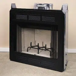
Installation and Operation Instructions
Superior
®
Residential and Outdoor Wood-Burning
Fireplace
Models:
WRE3042WS
WRE3042WH
WRE3042RS
WRE3042RH
SAVE THIS BOOK
This book is valuable. In addition to instructing you on how to install and maintain your appliance, it also
contains information that will enable you to obtain replacement parts or accessory items when needed. Keep
it with your other important papers.
INSTALLER: Leave this manual with the appliance.
CONSUMER: Retain this manual for future reference.
Installateur : Laissez cette notice avec l’appareil.
Consommateur : Conservez cette notice pour consultation ultérieure.
This wood burning fireplace complies with UL127
CAN/ULC-S610-M87 standard as a FACTORY
BUILT FIREPLACE.
Ce foyer au bois est conforme aux UL 127 CAN/ULC-
S610-M87 norme comme une USINE CONSTRUITE
CHEMINÉE.
This fireplace is approved for use as a wood burning fireplace or for use with a vented gas log approved to
ANS Z21.60, Z21.84 standards or for use with a vent-free gas log heater approved to ANS Z21.11.2 standard.
An INNOVATIVE HEARTH PRODUCTS, LLC hood must be installed when using a vent-free log heater (see Ac-
cessories, page 19).
FOR CANADA: The authority having jurisdiction
(such as the municipal building department, fire
department, etc.) should be contacted before
installation to determine the need to obtain a permit.
POUR LE CANADA: L’autorité compétente (comme le
service municipal du bâtiment, les pompiers, etc.) doit
être contacté avant l’installation afin de déterminer la
nécessité d’obtenir un permis.
This appliance may be installed in an aftermarket permanently located, manufactured home (USA only) or
mobile home, where not prohibited by local codes.
This installation manual will enable you to obtain a safe, efficient and dependable installation of your fireplace
system. Please read and understand these instructions before beginning your installation.
Do not alter or modify the fireplace or its components under any circumstances. Any modification or alteration of
the fireplace system, including but not limited to the fireplace, chimney components and accessories, may void the
warranty, listings and approvals of this system and could result in an unsafe and potentially dangerous installation.
IMPORTANT! TO ASSURE PROPER ALIGNMENT OF GLASS DOORS: INSTALL THIS FIREPLACE IN A SQUARE
AND PLUMB CONDITION, USING SHIMS AS NECESSARY AT SIDES AND/OR BOTTOM.
Superiorfireplaces.US.com
127055-01E
2
Safety .............................................................................................2
Specifications .................................................................................4
Fireplace Installation ......................................................................5
Venting Installation ........................................................................7
Optional Gas Line Installation ......................................................12
Operation and Maintenance .........................................................13
Replacement Parts .......................................................................14
Technical Service .........................................................................14
Parts ............................................................................................15
Accessories .................................................................................. 18
Warranty ......................................................................................23
Thank you for your purchase. We appreciate your
business!
Please carefully read and follow all instructions in this manual. Pay
special attention to all warnings and safety information.
Following these safety, care, and operation instructions will help
ensure many years of dependable and enjoyable service from your
fireplace.
Register your product online today!
To help us keep you up-to-date on product information and of-
fers, please take a few moments to register your product online
at Superiorfireplaces.US.com
Please read and understand these instructions before installing
or operating.
SAFETY
WARNING: Improper installation, adjustment,
alteration, service or maintenance can cause injury,
property damage or loss of life. Refer to this manual
for assistance or additional information. Consult a
qualified installer or local distributor.
IMPORTANT: Check local codes before installing this
fireplace.
Before beginning installation of this fireplace, read these instructions
through completely.
its components are safe when installed according to this installa-
designed and tested for the fireplace system, you may cause a fire
hazard.
-
sibility for the following actions.
a. Modification of the fireplace, components, doors, air inlet
system and damper control.
b. Use of any component part not manufactured or approved by
Proper installation is the most important step in ensuring safe and
as to the particular requirements concerned with the installation of
all factory built fireplaces.
WARNING: Do not install a fireplace insert in this
fireplace unless the manufacturer's instructions with
the insert specifically state this fireplace has been
tested for use with this insert.
NOTICE: The firebox canopy (hood) must not be modi-
fied or replaced with a canopy that may be provided
with the unvented decorative room heater.
TABLE OF CONTENTS
WARNING: Do not install a fireplace insert in this
box unless the manufacturer's instructions with the
insert specifically state this fireplace has been tested
for use with this insert.
FOR YOUR SAFETY
vapors or liquids in the vicinity of this or any other
appliance.
located out of traffic and away from furniture and
draperies.
on or near the appliance.
burning in the fireplace.
WARNING: Use solid wood or processed solid
fuel fire logs only. Do not poke or stir the logs while
they are burning. Use only firelogs that have been
evaluated for the application in fireplace and refer to
firelog warnings and caution markings on packaging
prior to use.
This fireplace is not intended to be used as a sub-
stitute for a furnace to heat an entire home. Use for
supplemental heat only.
Overfiring of a fireplace is a condition where exces-
sive temperatures are reached, beyond the design
capabilities of the appliance. The damage that occurs
from overfiring is not covered under the manufacturer’s
limited warranty.
Superiorfireplaces.US.com
127055-01E
3
SAFETY Continued
WARNING: CONTINUED OVERFIRING CAN PER-
MANENTLY DAMAGE YOUR FIREPLACE SYSTEM.
SOME EXAMPLES OF CONDITIONS THAT COULD
CAUSE OVERFIRING ARE:
• BURNINGQUANTITIESOFSCRAPLUMBER,PINE
BRANCHES, PAPER OR CARDBOARD BOXES
WHICHEXCEEDTHEVOLUMEOFTHENORMAL
LOGFIRE.
• BURNINGTRASH,CHEMICALSORCHEMICALLY
TREATEDCOMBUSTIBLES.
Disposal of Ashes
Ashes should be placed in a metal container with a
tight-fitting lid. The closed container of ashes should
well away from all combustible materials, pending
final disposal. If the ashes are disposed of by burial
in soil or otherwise locally dispersed, they should be
retained in the closed container until all cinders have
thoroughly cooled.
WHEN USING THE DECORATIVE APPLIANCE, THE
FIREPLACE DAMPER MUST BE SET IN THE FULLY
OPEN POSITION.
Never use gasoline, gasoline-type lantern fuel, kero-
or ’freshen up’ a fire in this fireplace. Keep all such
liquids well away from the fireplace while it is in use.
Use SOLID WOOD only for fuel. It is best to use dry
and well seasoned hardwood. Softwoods tend to burn
very quickly. DO NOT use treated wood, charcoal, coal,
trash, driftwood or woods that have been dipped in tar,
pitch, pine tar, creosote, etc. Wood products made
with synthetic binders, such as plywood, produce ab-
normally high temperatures and sputtering, smoking
fires. When burning artificial logs, please read and
follow the instructions provided by the manufacturer.
Never burn treated construction lumber or scraps.
These woods burn excessively hot and may contain
chemicals used to treat insects and fungus. When
burned, these chemicals can pose a significant hazard.
WARNING: BURNING IMPROPER FUEL (I.E.
CHARCOAL) CAN RESULT IN CARBON MONOXIDE
POISONING, WHICH MAY LEAD TO DEATH!
Carbon Monoxide Poisoning – Early signs of carbon
dizziness, or nausea. If you have these signs, get
fresh air at once! Have the appliance inspected by a
qualified service technician. Some people are more
affected by carbon monoxide than others. These
include pregnant women, people with heart or lung
-
cohol, and those at high altitudes.
Ventilation Requirements - Provide adequate air for
combustion. The fresh air requirements of this ap-
pliance must be met within the space where it will
be installed.
Smoke Detectors - Since there are always several
potential sources of fire in any home, we recommend
installing smoke detectors. If possible, install the
smoke detector in a hallway adjacent to the room (to
reduce the possibility of occasional false activation
from the heat produced by the appliance). If your local
code requires a smoke detector be installed within the
same room, you must follow the requirements of your
local code. Check with your local building department
for requirements in your area.
Creosote – Formation and Need for Removal
When wood is burned slowly, it produces tar and other
organic vapors, which combine with expelled moisture
to form creosote. The creosote vapors condense in
fire. As a result, creosote residue accumulates on
extremely hot fire.
The chimney shall be inspected at least twice a
year during the heating season to determine when a
creosote buildup has occurred. When creosote has
accumulated (1/8" [3 mm] or more) it shall be removed
to reduce the risk of a chimney fire.
Superiorfireplaces.US.com
127055-01E
4
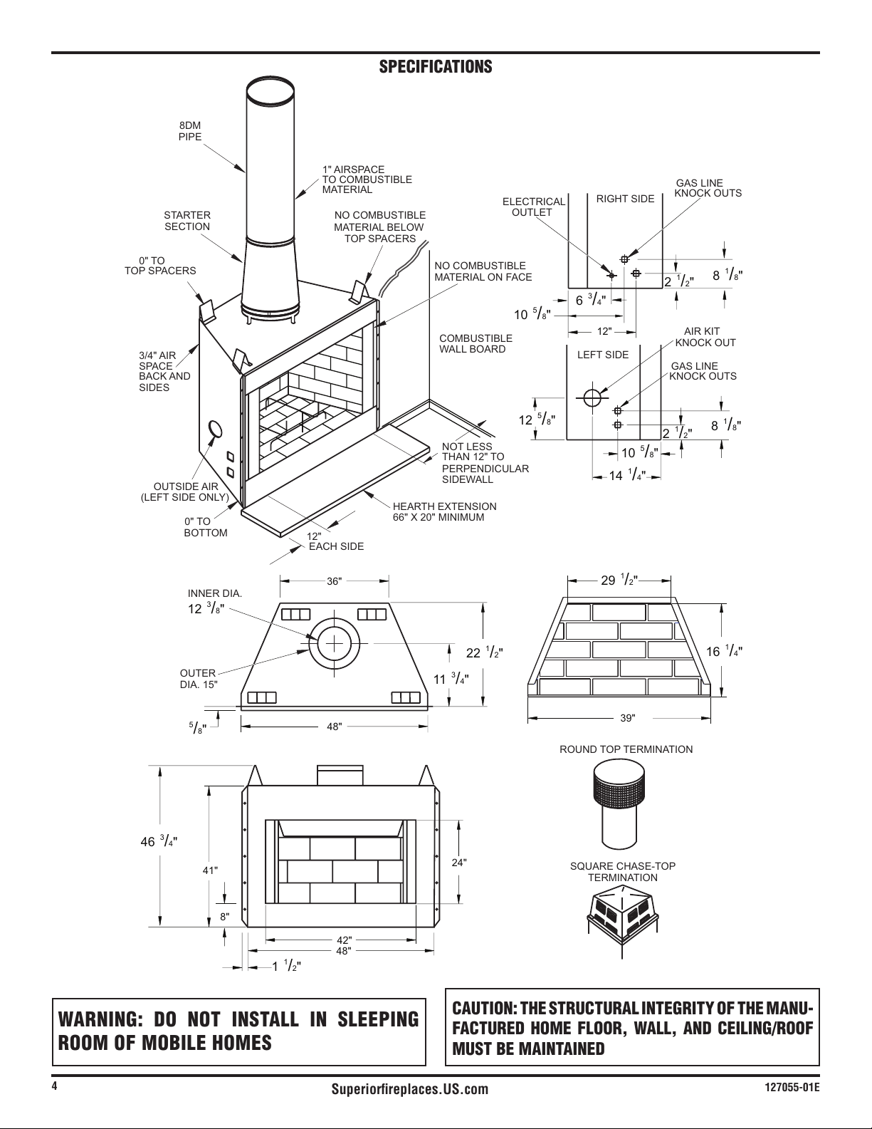
SPECIFICATIONS
WARNING: DO NOT INSTALL IN SLEEPING
ROOM OF MOBILE HOMES
CAUTION: THE STRUCTURAL INTEGRITY OF THE MANU-
FACTURED HOME FLOOR, WALL, AND CEILING/ROOF
MUST BE MAINTAINED
0" TO
BOTTOM
(LEFT SIDE ONLY)
OUTSIDE AIR
BACK AND
SIDES
3/4" AIR
SPACE
HEARTH EXTENSION
66" X 20" MINIMUM
12"
EACH SIDE
COMBUSTIBLE
WALL BOARD
TOP SPACERS
0" TO
1" AIRSPACE
TO COMBUSTIBLE
MATERIAL
NO COMBUSTIBLE
MATERIAL ON FACE
NO COMBUSTIBLE
MATERIAL BELOW
TOP SPACERS
GAS LINE
KNOCK OUT
AIR KIT
KNOCK OUTS
GAS LINE
STARTER
SECTION
8DM
PIPE
INNER DIA.
OUTER
DIA. 15"
KNOCK OUTS
ELECTRICAL
OUTLET
LEFT SIDE
RIGHT SIDE
PERPENDICULAR
NOT LESS
THAN 12" TO
SIDEWALL
41"
48"
42"
8"
39"
12"
48"
36"
24"
8
1
/8"
10
5
/8"
12
5
/8"
10
5
/8"
6
3
/4"
14
1
/4"
2
1
/2"
29
1
/2"
22
1
/2"
11
3
/4
"
46
3
/4"
1
1
/
2
"
12
3
/8"
5
/8"
16
1
/4"
8
1
/8"
2
1
/2"
SQUARE CHASE-TOP
TERMINATION
ROUND TOP TERMINATION
Superiorfireplaces.US.com
127055-01E
5
FIREPLACE INSTALLATION
SELECTING LOCATION
To determine safest and most efficient location for fireplace, you
must take into consideration the following guidelines:
air conditioning ducts, windows or doors.
3. A location that avoids cutting of joists or roof rafters will make
installation easier.
Optional
Outside Air Kit
MINIMUM CLEARANCE TO COMBUSTIBLES
Back and sides of fireplace 3/4" minimum*
Floor** 0" minimum
Perpendicular wall to opening 12" minimum
Top spacers 0" minimum
Mantel clearances see Mantels, page 6
** See step 2 of Framing
WARNING: DO NOT PACK REQUIRED AIR SPACES
WITH INSULATION OR OTHER MATERIALS.
Minimum/Maximum Chimney Height
The minimum height of the chimney, measured from the base of
the fireplace to the flue gas outlet of the termination, is 14.5 feet for
straight flue or a flue with one elbow set. The maximum distance
between elbows is 6 feet. For systems with two elbow sets, the
minimum height is 22 feet. The maximum height of any system is
50 feet. This measurement includes the fireplace, chimney sections
and the height of the termination assembly at the level of the flue
Minimum/Maximum Chimney Height for Outdoor Installation
The minimum height of the chimney, measured from the base of the
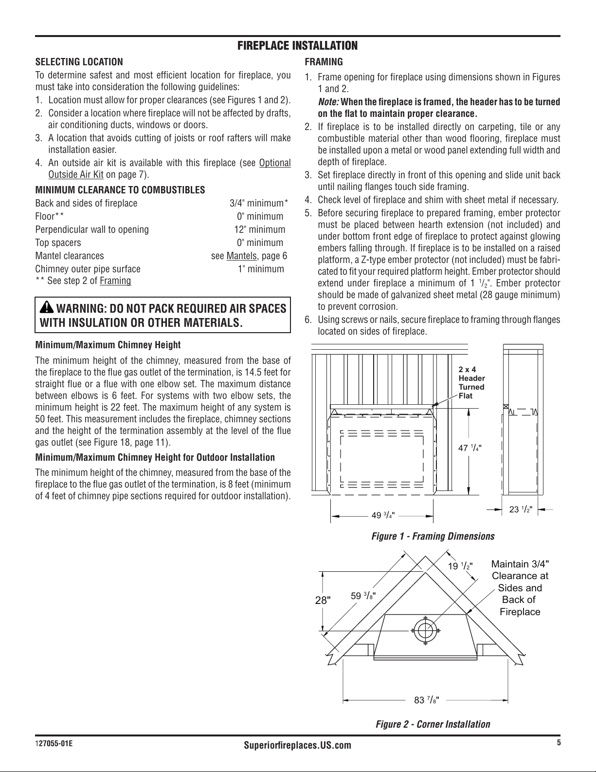
Figure 2 - Corner Installation
FRAMING
1. Frame opening for fireplace using dimensions shown in Figures
1 and 2.
Note: When the fireplace is framed, the header has to be turned
2. If fireplace is to be installed directly on carpeting, tile or any
combustible material other than wood flooring, fireplace must
be installed upon a metal or wood panel extending full width and
depth of fireplace.
3. Set fireplace directly in front of this opening and slide unit back
until nailing flanges touch side framing.
5. Before securing fireplace to prepared framing, ember protector
under bottom front edge of fireplace to protect against glowing
embers falling through. If fireplace is to be installed on a raised
-
extend under fireplace a minimum of 1
1
/
2
to prevent corrosion.
6. Using screws or nails, secure fireplace to framing through flanges
located on sides of fireplace.
28"
Maintain 3/4"
Clearance at
Sides and
Back of
Fireplace
59
3
/8"
19
1
/2"
83
7
/8"
Figure 1 - Framing Dimensions
23
1
/2"
49
3
/4"
47
1
/4"
2x4
Header
Turned
Flat
Superiorfireplaces.US.com
127055-01E
6
FIREPLACE INSTALLATION Continued
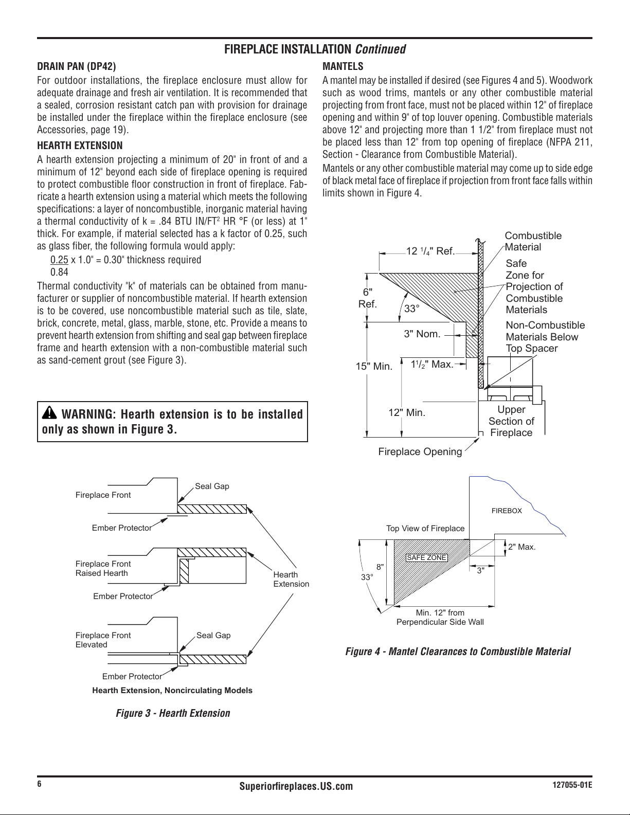
Figure 3 - Hearth Extension
Fireplace Front
Fireplace Front
Raised Hearth
Fireplace Front
Elevated
Seal Gap
Seal Gap
Ember Protector
Ember Protector
Ember Protector
Hearth
Extension
HearthExtension,NoncirculatingModels
WARNING: Hearth extension is to be installed
only as shown in Figure 3.
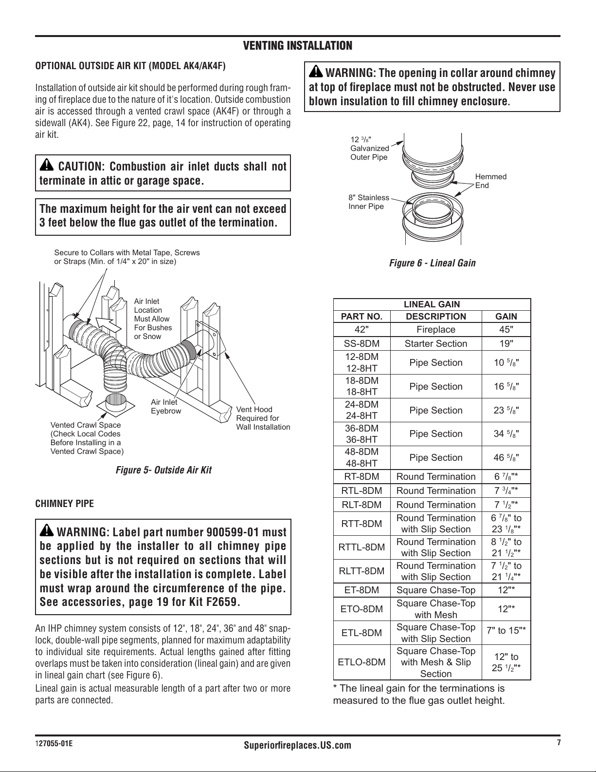
FIREBOX
SAFE ZONE
Top View of Fireplace
Min. 12" from
Perpendicular Side Wall
3"
2" Max.
33°
8"
MANTELS
such as wood trims, mantels or any other combustible material
projecting from front face, must not be placed within 12" of fireplace
above 12" and projecting more than 1 1/2" from fireplace must not
Mantels or any other combustible material may come up to side edge
of black metal face of fireplace if projection from front face falls within
limits shown in Figure 4.
Figure 4 - Mantel Clearances to Combustible Material
12
1
/
4
" Ref.
6"
Ref.
15" Min.
12" Min.
1
1
/
2
" Max.
3" Nom.
33°
Combustible
Material
Safe
Zone for
Projection of
Combustible
Materials
Fireplace Opening
Non-Combustible
Materials Below
Top Spacer
Upper
Section of
Fireplace
DRAIN PAN (DP42)
For outdoor installations, the fireplace enclosure must allow for
adequate drainage and fresh air ventilation. It is recommended that
a sealed, corrosion resistant catch pan with provision for drainage
HEARTH EXTENSION
A hearth extension projecting a minimum of 20" in front of and a
minimum of 12" beyond each side of fireplace opening is required
to protect combustible floor construction in front of fireplace. Fab-
ricate a hearth extension using a material which meets the following
specifications: a layer of noncombustible, inorganic material having
2
thick. For example, if material selected has a k factor of 0.25, such
as glass fiber, the following formula would apply:
0.25 x 1.0" = 0.30" thickness required
0.84
Thermal conductivity "k" of materials can be obtained from manu-
facturer or supplier of noncombustible material. If hearth extension
is to be covered, use noncombustible material such as tile, slate,
brick, concrete, metal, glass, marble, stone, etc. Provide a means to
prevent hearth extension from shifting and seal gap between fireplace
frame and hearth extension with a non-combustible material such
Superiorfireplaces.US.com
127055-01E
7
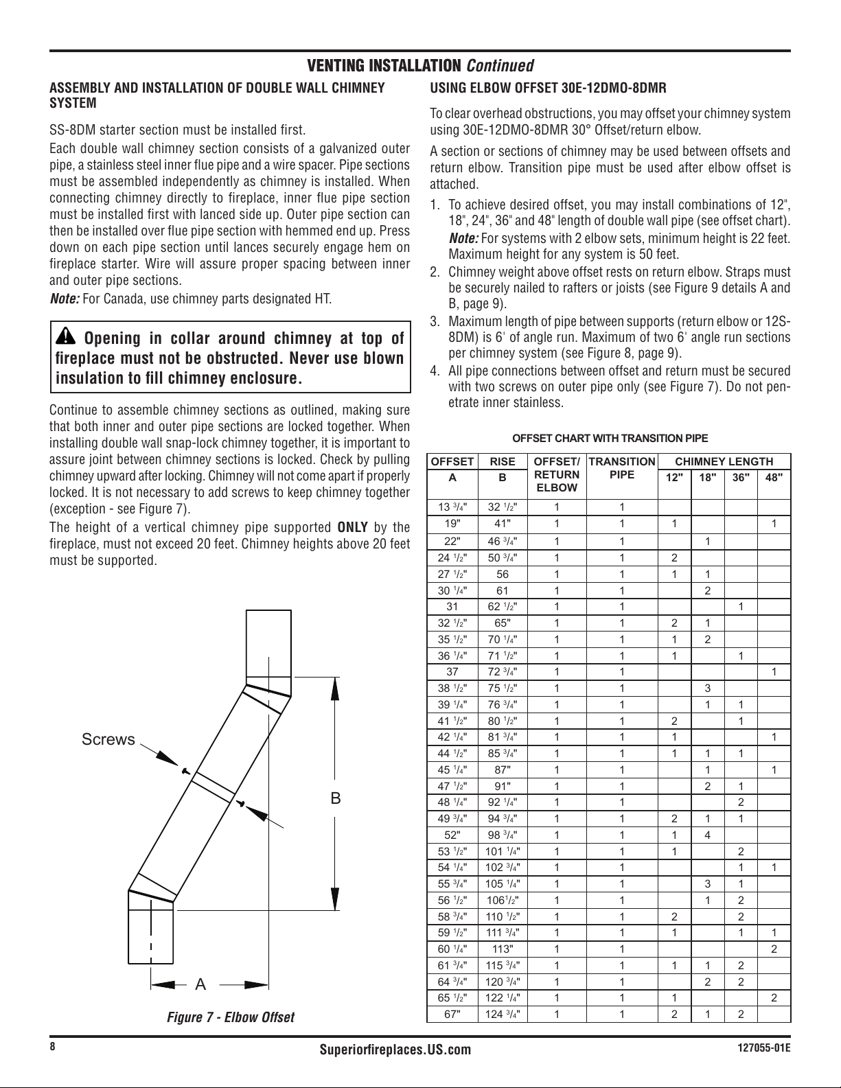
Figure 5- Outside Air Kit
Secure to Collars with Metal Tape, Screws
or Straps (Min. of 1/4" x 20" in size)
Air Inlet
Location
Must Allow
For Bushes
or Snow
Vent Hood
Required for
Wall Installation
Air Inlet
Eyebrow
Vented Crawl Space
(Check Local Codes
Before Installing in a
Vented Crawl Space)
VENTING INSTALLATION
OPTIONAL OUTSIDE AIR KIT (MODEL AK4/AK4F)
Installation of outside air kit should be performed during rough fram-
ing of fireplace due to the nature of it's location. Outside combustion
air kit.
CAUTION: Combustion air inlet ducts shall not
terminate in attic or garage space.
The maximum height for the air vent can not exceed
CHIMNEY PIPE
WARNING: Label part number 900599-01 must
be applied by the installer to all chimney pipe
sections but is not required on sections that will
be visible after the installation is complete. Label
must wrap around the circumference of the pipe.
See accessories, page 19 for Kit F2659.
lock, double-wall pipe segments, planned for maximum adaptability
to individual site requirements. Actual lengths gained after fitting
Lineal gain is actual measurable length of a part after two or more
parts are connected.
Figure 6 - Lineal Gain
Hemmed
End
8" Stainless
Inner Pipe
12
3
/
8
"
Galvanized
Outer Pipe
WARNING: The opening in collar around chimney
at top of fireplace must not be obstructed. Never use
blown insulation to fill chimney enclosure.
LINEALGAIN
PARTNO. DESCRIPTION GAIN
42" Fireplace 45"
SS-8DM Starter Section 19''
12-8DM
12-8HT
Pipe Section 10
5
/
8
"
18-8DM
18-8HT
Pipe Section 16
5
/
8
"
24-8DM
24-8HT
Pipe Section 23
5
/
8
"
36-8DM
36-8HT
Pipe Section 34
5
/
8
"
48-8DM
48-8HT
Pipe Section 46
5
/
8
"
RT-8DM Round Termination 6
7
/
8
"*
RTL-8DM Round Termination 7
3
/
4
"*
RLT-8DM Round Termination 7
1
/
2
"*
RTT-8DM
Round Termination
with Slip Section
6
7
/
8
" to
23
1
/
8
"*
RTTL-8DM
Round Termination
with Slip Section
8
1
/
2
" to
21
1
/
2
"*
RLTT-8DM
Round Termination
with Slip Section
7
1
/
2
" to
21
1
/
4
"*
ET-8DM Square Chase-Top 12"*
ETO-8DM
Square Chase-Top
with Mesh
12"*
ETL-8DM
Square Chase-Top
with Slip Section
7" to 15"*
ETLO-8DM
Square Chase-Top
with Mesh & Slip
Section
12" to
25
1
/
2
"*
* The lineal gain for the terminations is
Superiorfireplaces.US.com
127055-01E
8
VENTING INSTALLATION Continued
ASSEMBLY AND INSTALLATION OF DOUBLE WALL CHIMNEY
SYSTEM
SS-8DM starter section must be installed first.
pipe, a stainless steel inner flue pipe and a wire spacer. Pipe sections
must be assembled independently as chimney is installed. When
connecting chimney directly to fireplace, inner flue pipe section
must be installed first with lanced side up. Outer pipe section can
then be installed over flue pipe section with hemmed end up. Press
down on each pipe section until lances securely engage hem on
fireplace starter. Wire will assure proper spacing between inner
and outer pipe sections.
Note:
Opening in collar around chimney at top of
fireplace must not be obstructed. Never use blown
insulation to fill chimney enclosure.
that both inner and outer pipe sections are locked together. When
installing double wall snap-lock chimney together, it is important to
locked. It is not necessary to add screws to keep chimney together
The height of a vertical chimney pipe supported ONLY by the
must be supported.
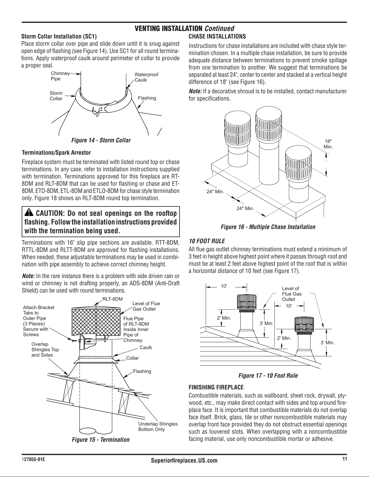
USING ELBOW OFFSET 30E-12DMO-8DMR
To clear overhead obstructions, you may offset your chimney system
using
A section or sections of chimney may be used between offsets and
return elbow. Transition pipe must be used after elbow offset is
attached.
1. To achieve desired offset, you may install combinations of 12",
Note: For systems with 2 elbow sets, minimum height is 22 feet.
Maximum height for any system is 50 feet.
4. All pipe connections between offset and return must be secured
-
etrate inner stainless.
Figure 7 - Elbow Offset
OFFSETCHARTWITHTRANSITIONPIPE
OFFSET RISE OFFSET/
RETURN
ELBOW
TRANSITION
PIPE
CHIMNEYLENGTH
A B 12" 18" 36" 48"
13
3
/
4
" 32
1
/
2
" 1 1
19" 41" 1 1 1 1
22" 46
3
/
4
" 1 1 1
24
1
/
2
" 50
3
/
4
" 1 1 2
27
1
/
2
" 56 1 1 1 1
30
1
/
4
" 61 1 1 2
31 62
1
/
2
" 1 1 1
32
1
/
2
" 65" 1 1 2 1
35
1
/
2
" 70
1
/
4
" 1 1 1 2
36
1
/
4
" 71
1
/
2
" 1 1 1 1
37 72
3
/
4
" 1 1 1
38
1
/
2
" 75
1
/
2
" 1 1 3
39
1
/
4
" 76
3
/
4
" 1 1 1 1
41
1
/
2
" 80
1
/
2
" 1 1 2 1
42
1
/
4
" 81
3
/
4
" 1 1 1 1
44
1
/
2
" 85
3
/
4
" 1 1 1 1 1
45
1
/
4
" 87" 1 1 1 1
47
1
/
2
" 91" 1 1 2 1
48
1
/
4
" 92
1
/
4
" 1 1 2
49
3
/
4
" 94
3
/
4
" 1 1 2 1 1
52" 98
3
/
4
" 1 1 1 4
53
1
/
2
" 101
1
/
4
" 1 1 1 2
54
1
/
4
" 102
3
/
4
" 1 1 1 1
55
3
/
4
" 105
1
/
4
" 1 1 3 1
56
1
/
2
" 106
1
/
2
" 1 1 1 2
58
3
/
4
" 110
1
/
2
" 1 1 2 2
59
1
/
2
" 111
3
/
4
" 1 1 1 1 1
60
1
/
4
" 113" 1 1 2
61
3
/
4
" 115
3
/
4
" 1 1 1 1 2
64
3
/
4
" 120
3
/
4
" 1 1 2 2
65
1
/
2
" 122
1
/
4
" 1 1 1 2
67" 124
3
/
4
" 1 1 2 1 2
B
A
Screws

Superiorfireplaces.US.com
127055-01E
9
Figure 9 - Ceiling Support Pipe 12S-8DM
2" Min.
Straps
Straps
Straps
Straps
Detail A
Return Elbow
Detail B
Angle
Firestop
See Detail A
See Detail B
Ceiling Support
Pipe 12S-8DM
VENTING INSTALLATION
Continued
Figure 8 - Typical Offset Installation
30E-8DM
Return Elbow
30E-8DM
Return Elbow
30E-8DM
Offset Elbow
30E-8DM
Offset Elbow
30E-12DMO-8DMR
Offset Elbow
30E-12DMO-8DMR
Offset Elbow
30E-12DMO-8DMR
Offset Elbow
30E-12DMO-8DMR
Return Elbow
30E-12DMO-8DMR
Return Elbow
30E-12DMO-8DMR
Return Elbow
Starter
Section
Starter
Section
Starter
Section
6' Max.
8 DM Pipe
8 DM Pipe
6' Max.
6' Max.
6' Max.
6' Max.
6' Max.
Ceiling
Support Pipe
12S-8DM
A B C
FIRESTOP SPACERS (3600FS-8DM-1)
Firestop spacers are required at each point where chimney penetrates
a floor space. Their purpose is to establish and maintain required
clearance between chimney and combustible materials. When pipe
passes through a framed opening into a living space above, firestop
must be placed onto ceiling from below as shown in Figure 10.
They also provide complete separation from one floor space to an-
other or attic space as required by most codes. When double wall
pipe passes through a framed opening into an attic space, firestop
must be placed into an attic floor as shown in Figure 11, page 10.
Figure 10 - Firestop Spacer with Living Space Above Ceiling
Existing
Ceiling
Frame
Firestop
Spacer
Screws or
Staples
(Min. of 8)

Superiorfireplaces.US.com
127055-01E
10
VENTING INSTALLATION Continued
Pitch Slope Opening
"A"Max.
UsedFlashing
ModelNo.
Flat 0° 15" V6F-8DM
0-6/12 26.6° 16
1
/
8
" V6F-8DM
6/12- 12/12 45.0° 20
3
/
8
" V12F-8DM
Figure 12 - Roof Opening Measurements
FLASHING INSTALLATION (V6F-8DM OR V12F-8DM)
Determine flashing to be used with roof opening chart. Slide flashing
over pipe until base is flat against roof. Replace as many shingles as
needed to cover exposed area and flashing base. Secure in position
Installing Flashing on a Metal Roof
When installing flashing on a metal roof, it is required that putty tape
be used between flashing and roof. Flashing must be secured to roof
using #8 x 3/4" screws and then sealed with roof coating to prevent
leakage through screw holes. A roof coating must also be applied
around perimeter of flashing to provide a proper seal.
Nail Only Outer
Perimeter of
Flashing
Storm Collar
Underlap Shingles
at Bottom
Figure 13 - Flashing Installation
Flashing
Cone
Overlap
Shingles Top
and Sides Only
Figure 11 - Firestop Spacer with Attic Space Above Ceiling
NOTICE: The installation of a firestop thimble (FST30
or 38FST) is recommended when negotiating a joist
and to prevent intrusion from insulation.
30"
(76.2 cm)
Minimum Measurements
Opening "A"
14
3
/
8
"
(48.3 cm)
1"
(2.54
cm)
1"
(2.54
cm)
1"
(2.54 cm)
Firestop
Spacer
Screws or Staples
(Min. of 8)
Existing
Ceiling
Frame
Figure 11a - Firestop Thimble
Thimble
38FST or
FST30
Firestop
PENETRATING ROOF
To maintain a 1" clearance to pipe on a roof with a pitch, a rectangular
opening must be cut.
1. Determine center point where pipe will penetrate the roof.
2. Determine center point of the roof. Pitch is the distance the roof
drops over a given span, usually 12". A 6/12 pitch means that the
roof drops 6" for each 12" measure horizontally down from roof
rafters.
length and flashing required.
sections of double wall pipe until pipe is minimum of 30" above
highest point of roof cutout. Termination and chimney must extend
a minimum of 36" above highest point where it passes through
roof.
Superiorfireplaces.US.com
127055-01E
11
VENTING INSTALLATION
Continued
CHASE INSTALLATIONS
Instructions for chase installations are included with chase style ter-
mination chosen. In a multiple chase installation, be sure to provide
adequate distance between terminations to prevent smoke spillage
from one termination to another. We suggest that terminations be
separated at least 24", center to center and stacked at a vertical height
Note: If a decorative shroud is to be installed, contact manufacturer
for specifications.
24" Min.
24" Min.
18"
Min.
Figure 16 - Multiple Chase Installation
10'
2' Min.
10'
3' Min.
2' Min.
3' Min.
Level of
Flue Gas
Outlet
Figure 17 - 10 Foot Rule
10 FOOT RULE
All flue gas outlet chimney terminations must extend a minimum of
3 feet in height above highest point where it passes through roof and
must be at least 2 feet above highest point of the roof that is within
FINISHING FIREPLACE
-
wood, etc., may make direct contact with sides and top around fire-
place face. It is important that combustible materials do not overlap
face itself. Brick, glass, tile or other noncombustible materials may
overlap front face provided they do not obstruct essential openings
such as louvered slots. When overlapping with a noncombustible
facing material, use only noncombustible mortar or adhesive.
Storm Collar Installation (SC1)
Place storm collar over pipe and slide down until it is snug against
-
tions. Apply waterproof caulk around perimeter of collar to provide
a proper seal.
Figure 14 - Storm Collar
Chimney
Pipe
Waterproof
Caulk
Storm
Collar
Flashing
Terminations/Spark Arrestor
Fireplace system must be terminated with listed round top or chase
terminations. In any case, refer to installation instructions supplied
with termination. Terminations approved for this fireplace are RT-
only. Figure 18 shows an RLT-8DM round top termination.
CAUTION: Do not seal openings on the rooftop
with the termination being used.
Terminations with 16" slip pipe sections are available. RTT-8DM,
RTTL-8DM and RLTT-8DM are approved for flashing installations.
When needed, these adjustable terminations may be used in combi-
nation with pipe assembly to achieve correct chimney height.
Note: In the rare instance there is a problem with side driven rain or
Attach Bracket
Tabs to
Outer Pipe
(3 Places)
Secure with
Screws
RLT-8DM
Level of Flue
Gas Outlet
Caulk
Collar
Flashing
Underlap Shingles
Bottom Only
Figure 15 - Termination
Overlap
Shingles Top
and Sides
Flue Pipe
of RLT-8DM
Inside Inner
Pipe of
Chimney

Superiorfireplaces.US.com
127055-01E
12
A gas line or gas log lighter may be installed for the purpose of
installing a vented or vent-free decorative gas appliance incorporat-
ing an automatic shutoff device and complying with the Standard
for Decorative Gas Appliances for Installation in Vented Fireplaces,
dated August, 1993.
unvented gas log sets which have been found to comply with the
in this fireplace.
Gas line hook up should be done by your supplier or a qualified
service person.
Note: Before you proceed, make sure your gas supply is turned off.
Use only a 1/2" black iron pipe and appropriate fittings.
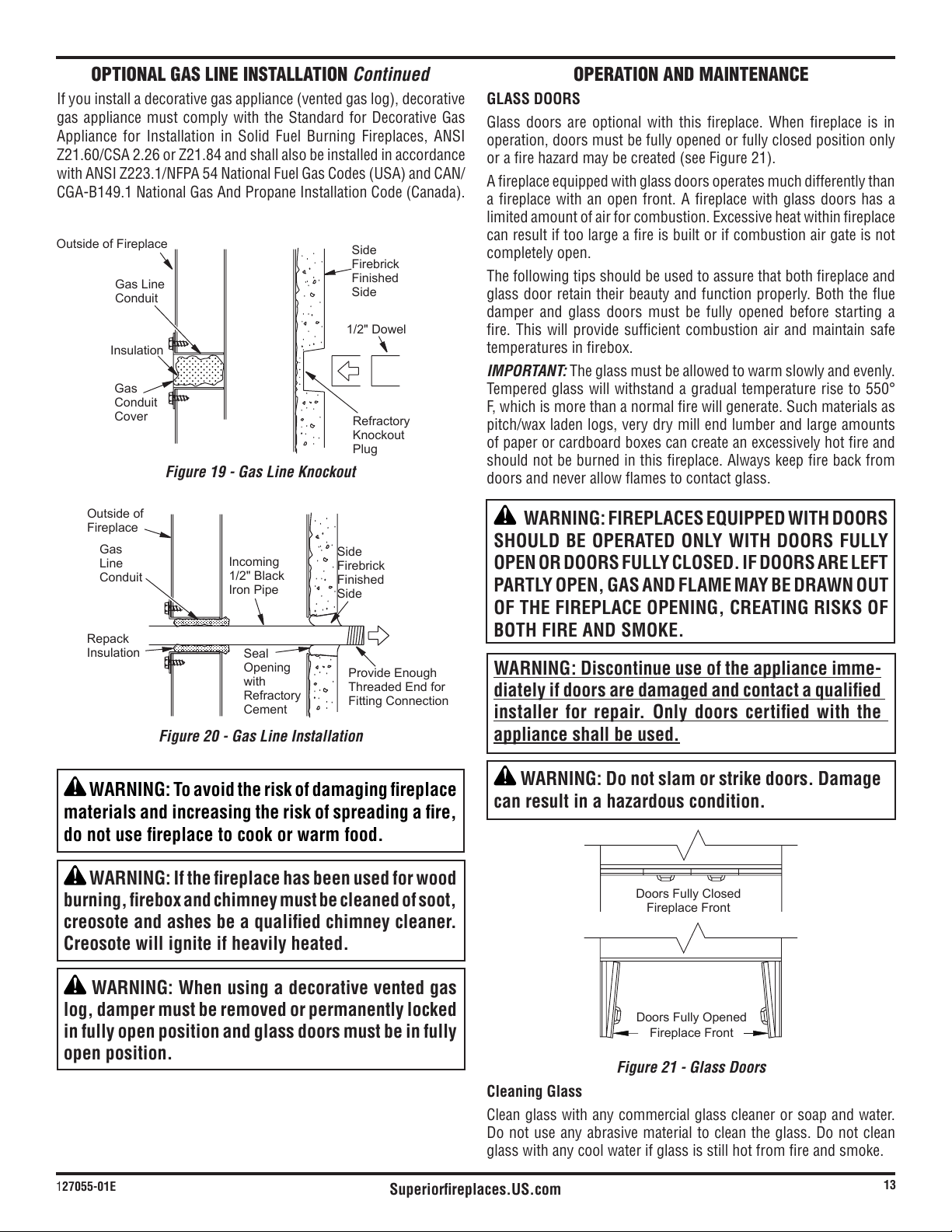
1. Remove knockout indentation on refractory or firebrick wall
located above refractory hearth floor. Knockout indentation must
be firmly tapped with any solid object, such as a 1/2" dowel, until
2. Remove gas line cover plate located on either side of fireplace and
pull out insulation from gas line conduit sleeve. Save insulation
for reuse.
3. Run a 1/2" black iron gas line into fireplace through rear at
Provide sufficient gas line into fireplace chamber for fitting
OPTIONAL GAS LINE INSTALLATION
VENTING INSTALLATION Continued
for threaded end.
4. Repack insulation around gas line and into sleeve opening. Seal
any gaps between gas line and refractory knockout hole with
refractory cement or commercial furnace cement. Install gas
appliance or cap off gas line if desired.
CAUTION: All gas piping and connections must be
tested for leaks after installation is completed. After
ensuring that gas valve is on, apply soap and water
solution to all connections and joints. Bubbles forming
show a leak. Correct all leaks at once. DO NOT USE
AN OPEN FLAME FOR LEAK TESTING AND DO NOT
OPERATE ANY APPLIANCE IF A LEAK IS DETECTED.
LEAK TESTING SHOULD BE DONE BY A QUALIFIED
SERVICE PERSON.
Note:
Accessories
WARNING: Do not operate an unvented gas log
set in this fireplace with chimney removed.
30E-12DMO-8DMR
30E-12DMO-8DMR
30E-12DMO-8DMR
EFFECTIVE HEIGHT
OF TERMINATION CAP
EFFECTIVE HEIGHT
OF TERMINATION CAP
EFFECTIVE HEIGHT
OF TERMINATION CAP
EFFECTIVE HEIGHT
OF TERMINATION CAP
MINIMUM
HEIGHT
14
1
/2 FT.
14
1
/2 FT.
MINIMUM
UP TO
6FT. MAX.
UP TO
6FT. MAX.
HEIGHT
STARTER
SECTION
STARTER
SECTION
MIN. HEIGHT
OF 22 FT. (WITH
2 ELBOW SETS)
MAX. HEIGHT OF
50 FT.
MAX. HEIGHT
50 FT.
(ANY SYSTEM)
STARTER
SECTION
Figure 21 - Typical Residential Installations
Superiorfireplaces.US.com
127055-01E
13
Figure 21 - Glass Doors
Cleaning Glass
Do not use any abrasive material to clean the glass. Do not clean
glass with any cool water if glass is still hot from fire and smoke.
OPERATION AND MAINTENANCE
Doors Fully Closed
Doors Fully Opened
Fireplace Front
Fireplace Front
GLASS DOORS
Glass doors are optional with this fireplace. When fireplace is in
operation, doors must be fully opened or fully closed position only
A fireplace equipped with glass doors operates much differently than
a fireplace with an open front. A fireplace with glass doors has a
can result if too large a fire is built or if combustion air gate is not
completely open.
The following tips should be used to assure that both fireplace and
glass door retain their beauty and function properly. Both the flue
damper and glass doors must be fully opened before starting a
fire. This will provide sufficient combustion air and maintain safe
temperatures in firebox.
IMPORTANT: The glass must be allowed to warm slowly and evenly.
F, which is more than a normal fire will generate. Such materials as
pitch/wax laden logs, very dry mill end lumber and large amounts
of paper or cardboard boxes can create an excessively hot fire and
should not be burned in this fireplace. Always keep fire back from
doors and never allow flames to contact glass.
WARNING: FIREPLACES EQUIPPED WITH DOORS
SHOULD BE OPERATED ONLY WITH DOORS FULLY
OPEN OR DOORS FULLY CLOSED. IF DOORS ARE LEFT
PARTLY OPEN, GAS AND FLAME MAY BE DRAWN OUT
OF THE FIREPLACE OPENING, CREATING RISKS OF
BOTH FIRE AND SMOKE.
WARNING: Discontinue use of the appliance imme-
diately if doors are damaged and contact a qualified
installer for repair. Only doors certified with the
appliance shall be used.
WARNING: Do not slam or strike doors. Damage
can result in a hazardous condition.
Figure 20 - Gas Line Installation
Figure 19 - Gas Line Knockout
Side
Firebrick
Finished
Side
Refractory
Knockout
Plug
Outside of Fireplace
Gas Line
Conduit
Insulation
Gas
Conduit
Cover
1/2" Dowel
Seal
Opening
with
Refractory
Cement
Outside of
Fireplace
Gas
Line
Conduit
Repack
Insulation
Incoming
1/2" Black
Iron Pipe
Side
Firebrick
Finished
Side
Provide Enough
Threaded End for
Fitting Connection
gas appliance must comply with the Standard for Decorative Gas
WARNING: To avoid the risk of damaging fireplace
materials and increasing the risk of spreading a fire,
do not use fireplace to cook or warm food.
WARNING: If the fireplace has been used for wood
burning, firebox and chimney must be cleaned of soot,
creosote and ashes be a qualified chimney cleaner.
Creosote will ignite if heavily heated.
WARNING: When using a decorative vented gas
log, damper must be removed or permanently locked
in fully open position and glass doors must be in fully
open position.
OPTIONAL GAS LINE INSTALLATION Continued
Superiorfireplaces.US.com
127055-01E
14
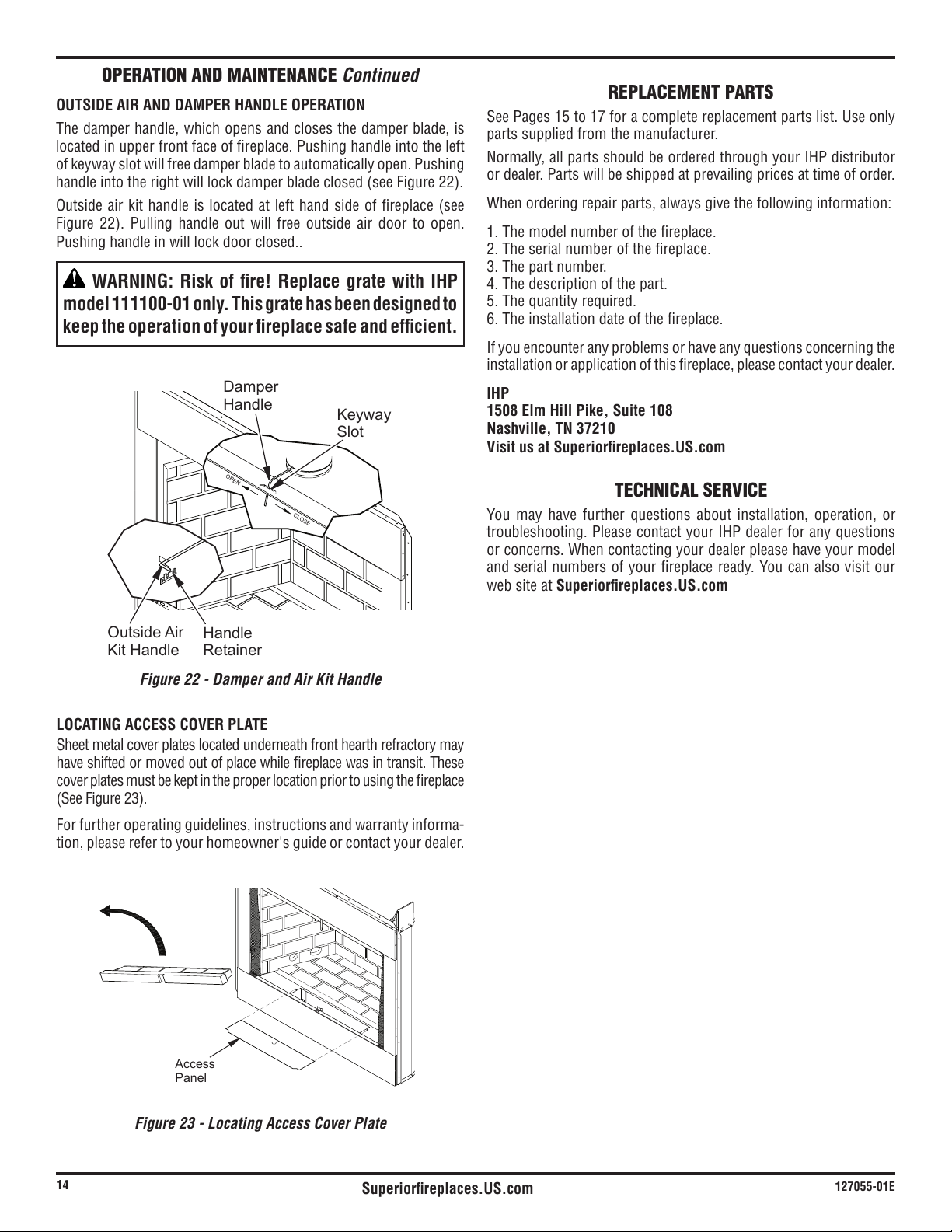
Figure 22 - Damper and Air Kit Handle
OPERATION AND MAINTENANCE Continued
OUTSIDE AIR AND DAMPER HANDLE OPERATION
The damper handle, which opens and closes the damper blade, is
located in upper front face of fireplace. Pushing handle into the left
of keyway slot will free damper blade to automatically open. Pushing
Pushing handle in will lock door closed..
WARNING: Risk of fire! Replace grate with IHP
model 111100-01 only. This grate has been designed to
keep the operation of your fireplace safe and efficient.
Figure 23 - Locating Access Cover Plate
LOCATING ACCESS COVER PLATE
Sheet metal cover plates located underneath front hearth refractory may
have shifted or moved out of place while fireplace was in transit. These
cover plates must be kept in the proper location prior to using the fireplace
For further operating guidelines, instructions and warranty informa-
tion, please refer to your homeowner's guide or contact your dealer.
Access
Panel
OPEN
CLOSE
Damper
Handle
Outside Air
Kit Handle
Keyway
Slot
Handle
Retainer
REPLACEMENT PARTS
See Pages 15 to 17 for a complete replacement parts list. Use only
parts supplied from the manufacturer.
or dealer. Parts will be shipped at prevailing prices at time of order.
When ordering repair parts, always give the following information:
1. The model number of the fireplace.
2. The serial number of the fireplace.
3. The part number.
4. The description of the part.
5. The quantity required.
6. The installation date of the fireplace.
If you encounter any problems or have any questions concerning the
installation or application of this fireplace, please contact your dealer.
IHP
1508 Elm Hill Pike, Suite 108
Nashville, TN 37210
Visit us at Superiorfireplaces.US.com
TECHNICAL SERVICE
You may have further questions about installation, operation, or
or concerns. When contacting your dealer please have your model
and serial numbers of your fireplace ready. You can also visit our
web site at Superiorfireplaces.US.com
Superiorfireplaces.US.com
127055-01E
15
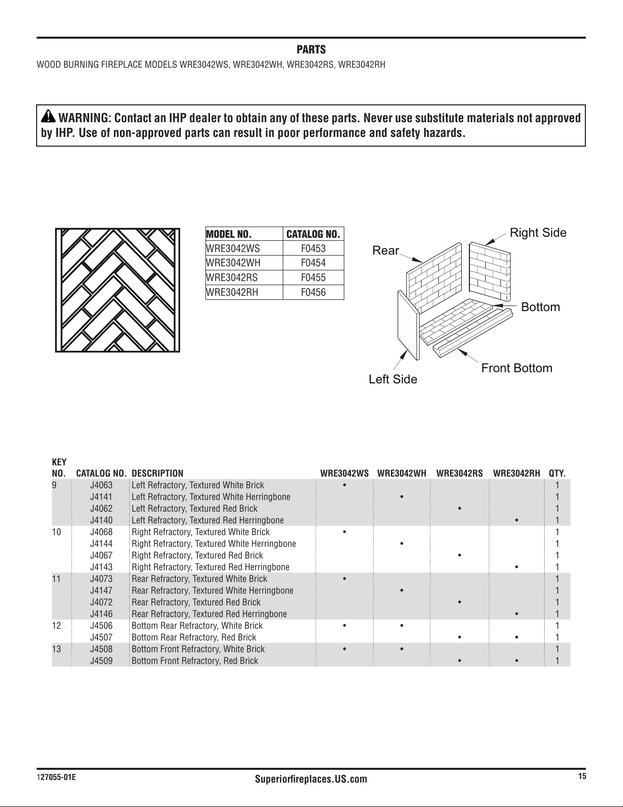
KEY
NO. CATALOG NO. DESCRIPTION WRE3042WS WRE3042WH WRE3042RS WRE3042RH QTY.
9 J4063 Left Refractory, Textured White Brick 1
J4141 1
J4062 Left Refractory, Textured Red Brick 1
J4140 1
10 J4068 Right Refractory, Textured White Brick 1
J4144 1
J4067 Right Refractory, Textured Red Brick 1
J4143 1
11 J4073 Rear Refractory, Textured White Brick 1
J4147 1
J4072 Rear Refractory, Textured Red Brick 1
J4146 1
12 J4506 Bottom Rear Refractory, White Brick 1
J4507 Bottom Rear Refractory, Red Brick 1
13 J4508 Bottom Front Refractory, White Brick 1
J4509 Bottom Front Refractory, Red Brick 1
PARTS
Rear
Left Side
Front Bottom
Bottom
Right Side
MODEL NO. CATALOG NO.
F0453
F0454
F0455
F0456
WARNING: Contact an IHP dealer to obtain any of these parts. Never use substitute materials not approved
by IHP. Use of non-approved parts can result in poor performance and safety hazards.

Superiorfireplaces.US.com
127055-01E
16
9
24
16
31
25
16
4
30
32
19
12
23
20
28
17
8
1
5
21
2
18
11
14
3
13
22
10
6
35
29
7
33/34
26
27
15
PARTS
MODEL NO. CATALOG NO.
F0453
F0454
F0455
F0456

Superiorfireplaces.US.com
127055-01E
17
WARNING: Contact an IHP dealer to obtain any of these parts. Never use substitute materials not approved
by IHP. Use of non-approved parts can result in poor performance and safety hazards.
WOOD BURNING FIREPLACE MODELS: WRE3042WS(F0453), WRE3042WH(F0454), WRE3042RS(F0455), WRE3042RH(F0546)
This list contains replaceable parts used in your fireplace.
KEY NO. CATALOG NO. DESCRIPTION
QTY.
1 ** Insulation Pan 1
2 ** Fireplace Top 1
3 ** Fireplace Surround 1
4 J3946 Air Rod Retainer 1
5 J3947 Damper Rod Retainer 1
6 ** Firebox Bottom 1
7 ** Firebox Surround 1
8 ** Air Separator 1
9 See Page 15 Left Refractory Brick Liner 1
10 See Page 15 Right Refractory Brick Liner 1
11 See Page 15 Rear Refractory Brick Liner 1
12 See Page 15 Bottom Rear Refractory Liner 1
13 See Page 15 Bottom Front Refractory Liner 1
14 J3972 Firebox Support Leg 4
15 ** 1
16 J8013 Kit, Screen Assembly 1
17 ** Firebox Top Assembly 1
18 J3980 Air Kit Door Assembly 1
19 ** Face Weldment 1
20 J4471 Air Deflector 1
21
** Fireplace Top Insulation 1
22 ** Access Panel 1
23 J4513 Grate 1
24 ** 1
25 J8014 1
26 J6895 Refractory Retainer 2
27 J3939 Grate Retainer 2
28 J4504 Door Stop 1
29 J4523 2
30 J6905 2
31 J6918 Top Spacer 4
32 J6934 4
33 J6951 2
34 J6952 2
35 F1907 1
PARTS AVAILABLE NOT SHOWN
127004-01 1
J6906 2
Superiorfireplaces.US.com
127055-01E
18
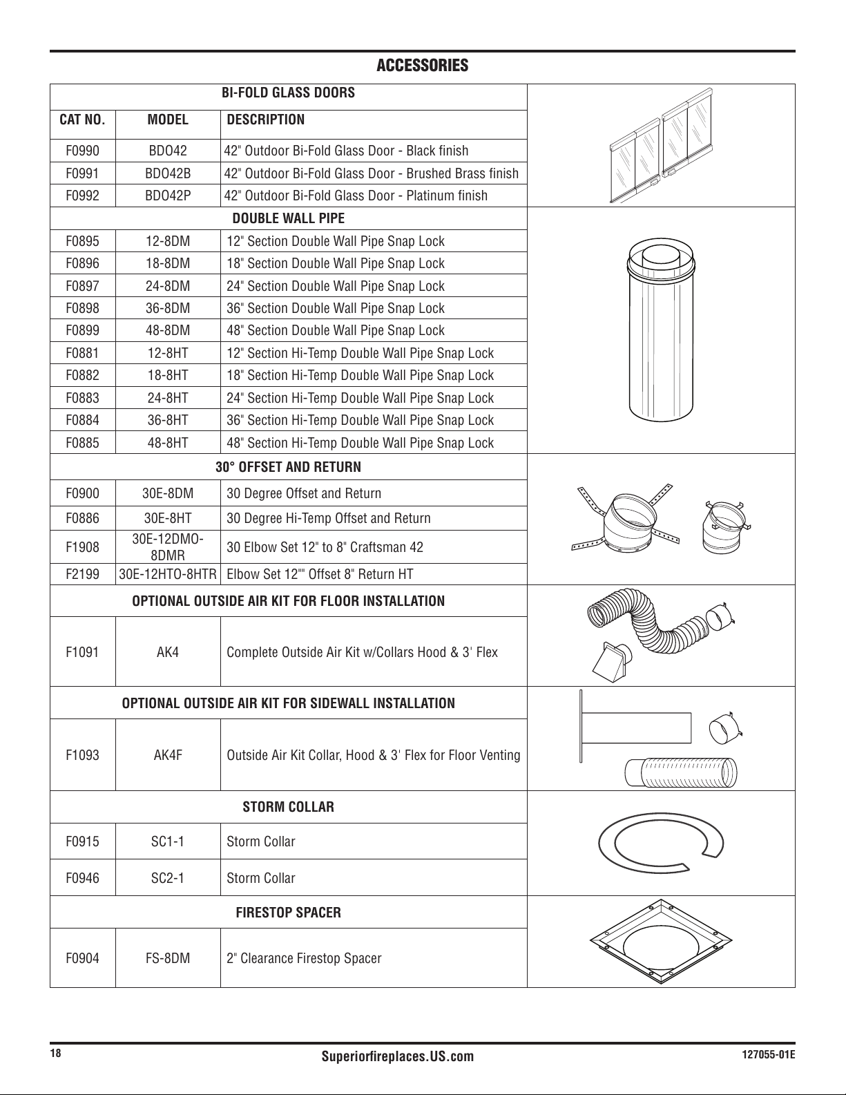
ACCESSORIES
BI-FOLD GLASS DOORS
CAT NO. MODEL DESCRIPTION
F0990 BDO42 42" Outdoor Bi-Fold Glass Door - Black finish
F0991 BDO42B 42" Outdoor Bi-Fold Glass Door - Brushed Brass finish
F0992 BDO42P 42" Outdoor Bi-Fold Glass Door - Platinum finish
DOUBLE WALL PIPE
F0895 12-8DM 12" Section Double Wall Pipe Snap Lock
F0896 18-8DM 18" Section Double Wall Pipe Snap Lock
F0897 24-8DM 24" Section Double Wall Pipe Snap Lock
F0898 36-8DM 36" Section Double Wall Pipe Snap Lock
F0899 48-8DM 48" Section Double Wall Pipe Snap Lock
F0881
F0882
F0883
F0884
F0885
30° OFFSET AND RETURN
F0900 30 Degree Offset and Return
F0886
F1908
8DMR
F2199
OPTIONAL OUTSIDE AIR KIT FOR FLOOR INSTALLATION
F1091 AK4
OPTIONAL OUTSIDE AIR KIT FOR SIDEWALL INSTALLATION
F1093 AK4F
STORM COLLAR
F0915
F0946
FIRESTOP SPACER
F0904 FS-8DM

Superiorfireplaces.US.com
127055-01E
19
ROOF FLASHING
F0909 V6F-8DM
F0910 V12F-8DM Roof Flashing 6/12 to12/12 Pitch
ANTI-DRAFT SHIELD
(Round Top Termination Only)
F0927 ADS-8DM Anti-Draft Shield for Round Top Only
MESH ROUND TOP TERMINATIONS
F0916 RT-8DM Round Top with Mesh Screen
MESH ROUND TOP TERMINATIONS WITH SLIP SECTION
F0917 RTT-8DM
ROUND TOP TERMINATIONS WITH LOUVERS
F0918 RLT-8DM Round Top with Louvered Screen
F0890
ROUND TOP TERMINATIONS WITH LOUVERS W/SLIP SECTION
F0919 RLTT-8DM
SQUARE TOP TERMINATION WITH LOUVERS
F0920 Square Top
F0922 Square Top with Mesh
SQUARE TOP TERMINATION WITH LOUVERS AND SLIP SECTION
F0921 Square Top with Slip Section
F0923 Square Top with Mesh and Slip Section
MESH SQUARE TOP TERMINATION
F0922 Square Top with Mesh
MESH SQUARE TOP TERMINATION WITH SLIP SECTION
F0923 Square Top with Mesh and Slip Section
STAINLESS STEEL HOOD
Required when installing a vent-free gas log in this fireplace.
F1053
DRAIN PAN
F1090 DP42 Drain Pan
FIRESTOP THIMBLE
F0911 38FST
F0912 FST30
LABEL-UL127-50PK
WARNING
HOT
Fire Risk
Insulation and combustibles must not touch
pipe
Consult manual for clearance requirements
Ensure proper connection
WARNING
HOT
Fire Risk
Insulation and combustibles must not touch
pipe
Consult manual for clearance requirements
Ensure proper connection
WARNING
HOT
Fire Risk
Insulation and combustibles must not touch
pipe
Consult manual for clearance requirements
Ensure proper connection
900599-01
F2659
50PK
UL127 Venting Label - 50 PK
ACCESSORIES
Continued
Superiorfireplaces.US.com
127055-01E
20
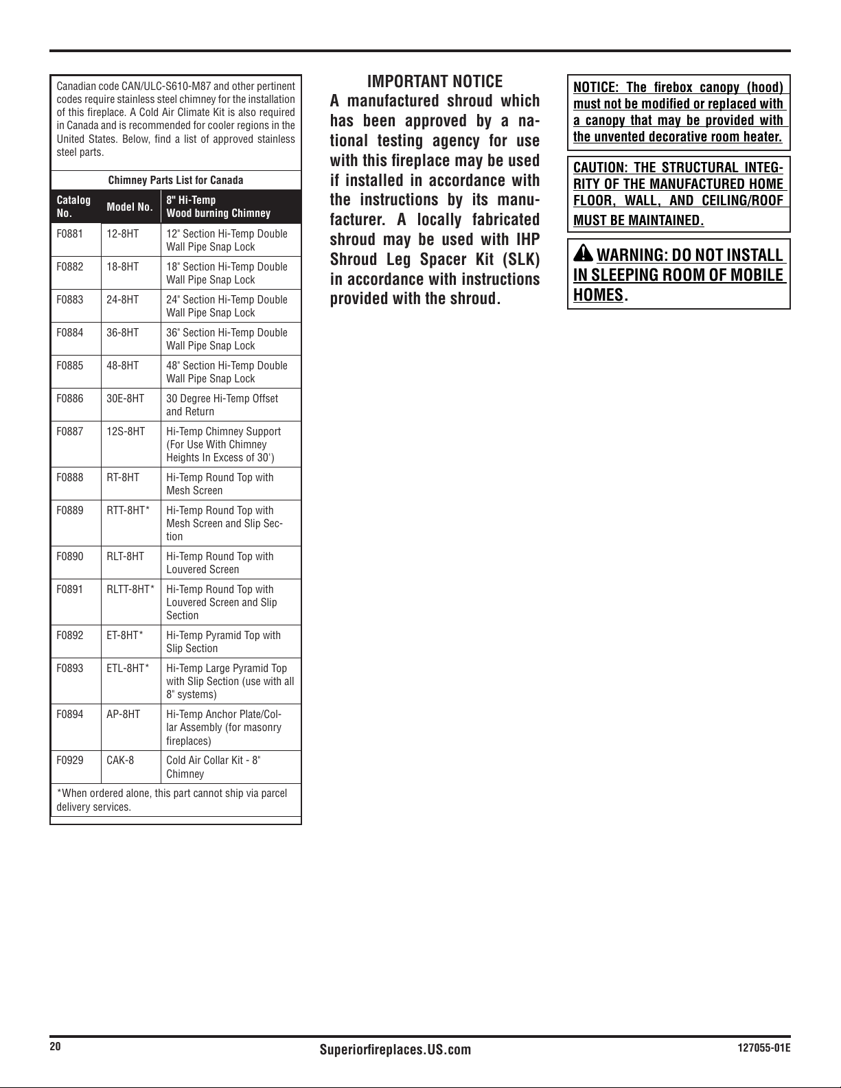
IMPORTANT NOTICE
A manufactured shroud which
has been approved by a na-
tional testing agency for use
with this fireplace may be used
if installed in accordance with
the instructions by its manu-
facturer. A locally fabricated
shroud may be used with IHP
Shroud Leg Spacer Kit (SLK)
in accordance with instructions
provided with the shroud.
codes require stainless steel chimney for the installation
United States. Below, find a list of approved stainless
steel parts.
Chimney Parts List for Canada
Catalog
No.
Model No.
8" Hi-Temp
Wood burning Chimney
F0881
Wall Pipe Snap Lock
F0882
Wall Pipe Snap Lock
F0883
Wall Pipe Snap Lock
F0884
Wall Pipe Snap Lock
F0885
Wall Pipe Snap Lock
F0886
and Return
F0887
F0888
Mesh Screen
F0889
Mesh Screen and Slip Sec-
tion
F0890
Louvered Screen
F0891
Louvered Screen and Slip
Section
F0892
Slip Section
F0893
F0894 -
F0929
*When ordered alone, this part cannot ship via parcel
delivery services.
NOTICE: The firebox canopy (hood)
must not be modified or replaced with
a canopy that may be provided with
the unvented decorative room heater.
CAUTION: THE STRUCTURAL INTEG-
RITY OF THE MANUFACTURED HOME
FLOOR, WALL, AND CEILING/ROOF
MUST BE MAINTAINED.
WARNING: DO NOT INSTALL
IN SLEEPING ROOM OF MOBILE
HOMES.

Superiorfireplaces.US.com
127055-01E
21
______________________________________________________
______________________________________________________
______________________________________________________
______________________________________________________
______________________________________________________
______________________________________________________
______________________________________________________
______________________________________________________
______________________________________________________
______________________________________________________
______________________________________________________
______________________________________________________
______________________________________________________
______________________________________________________
______________________________________________________
______________________________________________________
______________________________________________________
______________________________________________________
______________________________________________________
______________________________________________________
______________________________________________________
______________________________________________________
______________________________________________________
______________________________________________________
______________________________________________________
______________________________________________________
______________________________________________________
______________________________________________________
______________________________________________________
______________________________________________________
______________________________________________________
______________________________________________________
______________________________________________________
______________________________________________________
______________________________________________________
______________________________________________________
______________________________________________________
NOTES

Superiorfireplaces.US.com
127055-01E
22
______________________________________________________
______________________________________________________
______________________________________________________
______________________________________________________
______________________________________________________
______________________________________________________
______________________________________________________
______________________________________________________
______________________________________________________
______________________________________________________
______________________________________________________
______________________________________________________
______________________________________________________
______________________________________________________
______________________________________________________
______________________________________________________
______________________________________________________
______________________________________________________
______________________________________________________
______________________________________________________
______________________________________________________
______________________________________________________
______________________________________________________
______________________________________________________
______________________________________________________
______________________________________________________
______________________________________________________
______________________________________________________
______________________________________________________
______________________________________________________
______________________________________________________
______________________________________________________
______________________________________________________
______________________________________________________
______________________________________________________
______________________________________________________
______________________________________________________
NOTES
Superiorfireplaces.US.com
127055-01E
23
Printed in U.S.A. © 2013 Innovative Hearth Products
P/N 900224-00, Rev. A 10/2015
Innovative Hearth Products
1508 Elm Hill Pike, Suite 108 • Nashville, TN 37210
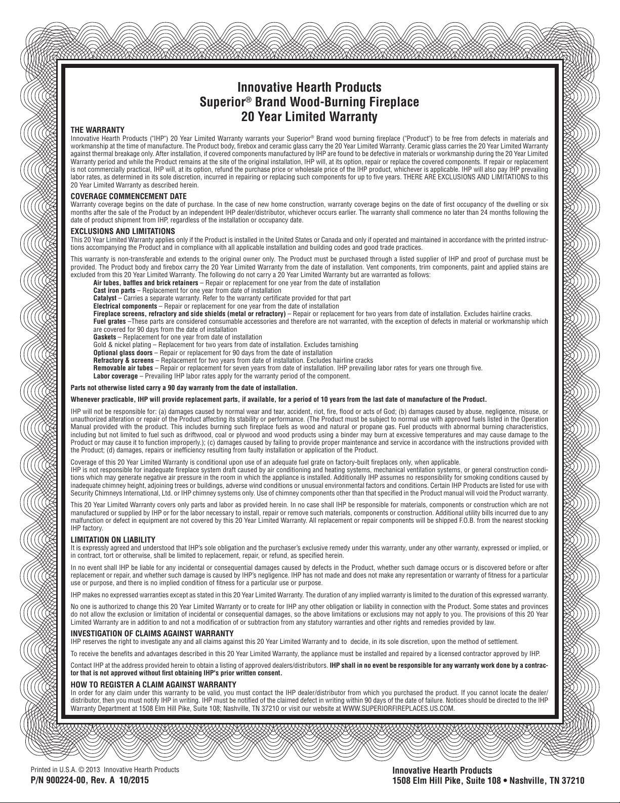
Innovative Hearth Products
Superior
®
Brand Wood-Burning Fireplace
20 Year Limited Warranty
THE WARRANTY
Innovative Hearth Products ("IHP") 20 Year Limited Warranty warrants your Superior
®
Brand wood burning fi replace ("Product") to be free from defects in materials and
workmanship at the time of manufacture. The Product body, fi rebox and ceramic glass carry the 20 Year Limited Warranty. Ceramic glass carries the 20 Year Limited Warranty
against thermal breakage only. After installation, if covered components manufactured by IHP are found to be defective in materials or workmanship during the 20 Year Limited
Warranty period and while the Product remains at the site of the original installation, IHP will, at its option, repair or replace the covered components. If repair or replacement
is not commercially practical, IHP will, at its option, refund the purchase price or wholesale price of the IHP product, whichever is applicable. IHP will also pay IHP prevailing
labor rates, as determined in its sole discretion, incurred in repairing or replacing such components for up to fi ve years. THERE ARE EXCLUSIONS AND LIMITATIONS to this
20 Year Limited Warranty as described herein.
COVERAGE COMMENCEMENT DATE
Warranty coverage begins on the date of purchase. In the case of new home construction, warranty coverage begins on the date of fi rst occupancy of the dwelling or six
months after the sale of the Product by an independent IHP dealer/distributor, whichever occurs earlier. The warranty shall commence no later than 24 months following the
date of product shipment from IHP, regardless of the installation or occupancy date.
EXCLUSIONS AND LIMITATIONS
This 20 Year Limited Warranty applies only if the Product is installed in the United States or Canada and only if operated and maintained in accordance with the printed instruc-
tions accompanying the Product and in compliance with all applicable installation and building codes and good trade practices.
This warranty is non-transferable and extends to the original owner only. The Product must be purchased through a listed supplier of IHP and proof of purchase must be
provided. The Product body and fi rebox carry the 20 Year Limited Warranty from the date of installation. Vent components, trim components, paint and applied stains are
excluded from this 20 Year Limited Warranty. The following do not carry a 20 Year Limited Warranty but are warranted as follows:
Air tubes, baffl es and brick retainers – Repair or replacement for one year from the date of installation
Cast iron parts – Replacement for one year from date of installation
Catalyst – Carries a separate warranty. Refer to the warranty certifi cate provided for that part
Electrical components – Repair or replacement for one year from the date of installation
Fireplace screens, refractory and side shields (metal or refractory) – Repair or replacement for two years from date of installation. Excludes hairline cracks.
Fuel grates –These parts are considered consumable accessories and therefore are not warranted, with the exception of defects in material or workmanship which
are covered for 90 days from the date of installation
Gaskets – Replacement for one year from date of installation
Gold & nickel plating – Replacement for two years from date of installation. Excludes tarnishing
Optional glass doors – Repair or replacement for 90 days from the date of installation
Refractory & screens – Replacement for two years from date of installation. Excludes hairline cracks
Removable air tubes – Repair or replacement for seven years from date of installation. IHP prevailing labor rates for years one through fi ve.
Labor coverage – Prevailing IHP labor rates apply for the warranty period of the component.
Parts not otherwise listed carry a 90 day warranty from the date of installation.
Whenever practicable, IHP will provide replacement parts, if available, for a period of 10 years from the last date of manufacture of the Product.
IHP will not be responsible for: (a) damages caused by normal wear and tear, accident, riot, fi re, fl ood or acts of God; (b) damages caused by abuse, negligence, misuse, or
unauthorized alteration or repair of the Product affecting its stability or performance. (The Product must be subject to normal use with approved fuels listed in the Operation
Manual provided with the product. This includes burning such fi replace fuels as wood and natural or propane gas. Fuel products with abnormal burning characteristics,
including but not limited to fuel such as driftwood, coal or plywood and wood products using a binder may burn at excessive temperatures and may cause damage to the
Product or may cause it to function improperly.); (c) damages caused by failing to provide proper maintenance and service in accordance with the instructions provided with
the Product; (d) damages, repairs or ineffi ciency resulting from faulty installation or application of the Product.
Coverage of this 20 Year Limited Warranty is conditional upon use of an adequate fuel grate on factory-built fi replaces only, when applicable.
IHP is not responsible for inadequate fi replace system draft caused by air conditioning and heating systems, mechanical ventilation systems, or general construction condi-
tions which may generate negative air pressure in the room in which the appliance is installed. Additionally IHP assumes no responsibility for smoking conditions caused by
inadequate chimney height, adjoining trees or buildings, adverse wind conditions or unusual environmental factors and conditions. Certain IHP Products are listed for use with
Security Chimneys International, Ltd. or IHP chimney systems only. Use of chimney components other than that specifi ed in the Product manual will void the Product warranty.
This 20 Year Limited Warranty covers only parts and labor as provided herein. In no case shall IHP be responsible for materials, components or construction which are not
manufactured or supplied by IHP or for the labor necessary to install, repair or remove such materials, components or construction. Additional utility bills incurred due to any
malfunction or defect in equipment are not covered by this 20 Year Limited Warranty. All replacement or repair components will be shipped F.O.B. from the nearest stocking
IHP factory.
LIMITATION ON LIABILITY
It is expressly agreed and understood that IHP’s sole obligation and the purchaser’s exclusive remedy under this warranty, under any other warranty, expressed or implied, or
in contract, tort or otherwise, shall be limited to replacement, repair, or refund, as specifi ed herein.
In no event shall IHP be liable for any incidental or consequential damages caused by defects in the Product, whether such damage occurs or is discovered before or after
replacement or repair, and whether such damage is caused by IHP’s negligence. IHP has not made and does not make any representation or warranty of fi tness for a particular
use or purpose, and there is no implied condition of fi tness for a particular use or purpose.
IHP makes no expressed warranties except as stated in this 20 Year Limited Warranty. The duration of any implied warranty is limited to the duration of this expressed warranty.
No one is authorized to change this 20 Year Limited Warranty or to create for IHP any other obligation or liability in connection with the Product. Some states and provinces
do not allow the exclusion or limitation of incidental or consequential damages, so the above limitations or exclusions may not apply to you. The provisions of this 20 Year
Limited Warranty are in addition to and not a modifi cation of or subtraction from any statutory warranties and other rights and remedies provided by law.
INVESTIGATION OF CLAIMS AGAINST WARRANTY
IHP reserves the right to investigate any and all claims against this 20 Year Limited Warranty and to decide, in its sole discretion, upon the method of settlement.
To receive the benefi ts and advantages described in this 20 Year Limited Warranty, the appliance must be installed and repaired by a licensed contractor approved by IHP.
Contact IHP at the address provided herein to obtain a listing of approved dealers/distributors. IHP shall in no event be responsible for any warranty work done by a contrac-
tor that is not approved without fi rst obtaining IHP's prior written consent.
HOW TO REGISTER A CLAIM AGAINST WARRANTY
In order for any claim under this warranty to be valid, you must contact the IHP dealer/distributor from which you purchased the product. If you cannot locate the dealer/
distributor, then you must notify IHP in writing. IHP must be notifi ed of the claimed defect in writing within 90 days of the date of failure. Notices should be directed to the IHP
Warranty Department at 1508 Elm Hill Pike, Suite 108; Nashville, TN 37210 or visit our website at WWW.SUPERIORFIREPLACES.US.COM.
your local distributor for fireplace code information.
P127055-01
WARRANTY
KEEP THIS WARRANTY
Date Installed
Keep receipt for warranty verification