Loading ...
Loading ...
Loading ...
www.dimplex.de 452237.66.01 · FD 9506 EN5
English
SI 26TU - SI 35TU
6 Installation
6.1 General Information
The brine-to-water heat pump must be installed in a frost-free,
dry room on an even, smooth and horizontal surface. The entire
base of the frame should lie directly on the floor to ensure an ad-
equate soundproof seal. If this is not the case, additional sound
insulation measures may be necessary.
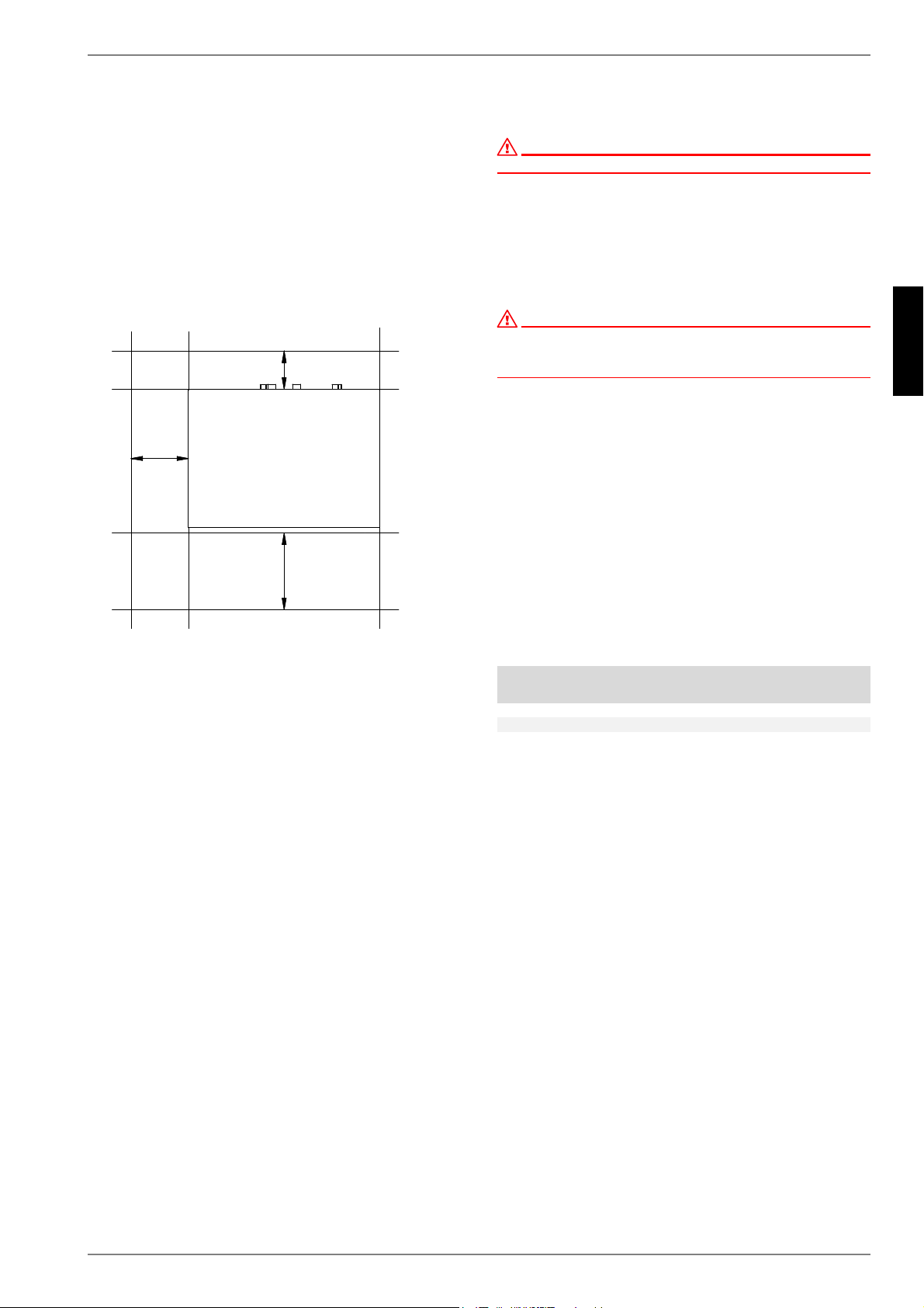
The heat pump must be installed so that maintenance work can
be carried out without hindrance. This can be ensured by main-
taining a clearance of approx. 1 m in front of the heat pump.
Neither frost nor temperatures higher than 35? must occur in the
installation location at any time of the year.
6.2 Acoustic Emissions
The heat pump operates silently due to efficient sound insulation.
Internal insulation measures should be carried out to prevent vi-
brations from being transmitted to the foundation or to the heat-
ing system.
7 Installation
7.1 General
The following connections need to be established on the heat
pump. The hydraulic integration diagram must be adhered to:
Flow and return of the brine (heat source system)
Flow and return of the heating system
Temperature sensor
Voltage supply
7.2 Connection on the heating side
ATTENTION!
Flush the heating system prior to connecting the heat pump.
Before connecting the heating water system to the heat pump,
the heating system must be flushed to remove any impurities,
residue from sealants, etc. Any accumulation of deposits in the
liquifier could cause the heat pump to completely break down.
Once the heat pump has been connected to the heating system,
it must be filled, de-aerated and pressure-tested.
ATTENTION!
The maximum test pressure in the heating circuit and the brine circuit is
6.0 bar.
This value must not be exceeded.
The following points must be observed when filling the system:
Untreated filling water and make-up water must be of drink-
ing water quality.
(colourless, clear, free of sediments)
Filling water and make-up water must be pre-filtered (max.
pore size 5 µm).
Scale formation in hot water heating systems cannot be com-
pletely avoided, but in systems with flow temperatures below
60 °C, the problem can be disregarded.
With medium and high-temperature heating systems, tempera-
tures above 60 °C can be reached.
The following standard values should therefore be adhered to re-
garding the filling and make-up water according to VDI 2035,
sheet 1:
Minimum heating water flow rate
The minimum heating water flow rate through the heat pump
must be assured in all operating states of the heating system.
This can be accomplished, for example, by installing a dual dif-
ferential pressureless manifold.
The frost protection function of the heat pump manager is active
whenever the heat pump manager and the heat circulating
pumps are ready for operation. The system must be drained if
the heat pump is taken out of service or in the event of a power
failure. If heat pump systems are implemented in buildings where
a power failure cannot be detected (holiday homes etc.), the
heating circuit should be operated with suitable frost protection.
P
P
P
Total heat
output in [kW]
Total alkaline earths
in mol/m³ and/or
mmol/l
Total
hardness in °dH
up to 200
2,0 11,2
200 to 600
1,5 8,4
> 600 < 0,02 < 0,11
Loading ...
Loading ...
Loading ...