Loading ...
Loading ...
Loading ...
www.dimplex.de 452237.66.01 · FD 9506 EN3
English
SI 26TU - SI 35TU
1.4 Energy-efficient use of the heat
pump
By operating this heat pump you are helping to protect our envi-
ronment. Both the heating system and the heat source must be
properly designed and dimensioned to ensure efficient operation.
It is particularly important to keep water flow temperatures as low
as possible. All connected heat consumers should therefore be
suitable for low flow temperatures. Raising the heating water
temperature by 1 K corresponds to an increase in electricity con-
sumption of approx. 2.5 %. Low-temperature heating systems
with flow temperatures between 30 °C and 50 °C are particularly
well-suited for energy-efficient operation.
2 Intended use of the heat
pump
2.1 Intended purpose
The brine-to-water heat pump is to be used exclusively for the
heating of heating water. It can be used in new or existing heat-
ing systems. A mixture of water and frost protection (brine) is
used as a heat transfer medium in the heat source system. Bore-
hole heat exchangers, ground heat collectors or similar systems
can be used as the heat source system.
2.2 Operating principle
The heat generated by the sun, wind and rain is stored in the
ground. This heat stored in the ground is collected at a low tem-
perature by the brine circulating in the ground heat collector, the
borehole heat exchanger or a similar system. A circulating pump
then conveys the "heated" brine to the evaporator of the heat
pump. There the heat is given off to the refrigerant in the refriger-
ation circuit. This cools the brine so that it can once again absorb
thermal energy in the brine circuit.
The refrigerant is drawn in by the electrically driven compressor,
compressed and "pumped" to a higher temperature level. The
electrical power needed to run the compressor is not lost in this
process. Most of it is absorbed by the refrigerant.
The refrigerant subsequently passes through the liquifier where it
transfers its thermal energy to the heating water. Depending on
the set operating point, the heating water can thus be heated up
to a max. of 62 °C.
3 Basic device
The device consists of a heat pump for indoor installation wired
ready for use with metal casing, switch box and integrated heat
pump manager. The refrigeration circuit contains the Kyoto pro-
tocol-approved fluorinated refrigerant R410A with a GWP value
of 2088. It is CFC-free, does not deplete ozone and is non-flam-
mable.
All components required for the operation of the heat pump are
located in the switch box. An outside temperature sensor includ-
ing fixing accessories and a dirt trap are supplied with the heat
pump. The supply for the supply voltage and the control voltage
must be installed by the customer.
The circulating pumps (brine and heating water side) included in
the scope of supply must be installed in accordance with the hy-
draulic diagrams (see Cap. 4 on pag. XX) or the development
documents. The electrical connection of the circulating pumps
must be established in accordance with Cap. 7.5.3 on pag. 8.
The customer must provide both the heat source system and the
brine circuit manifold.
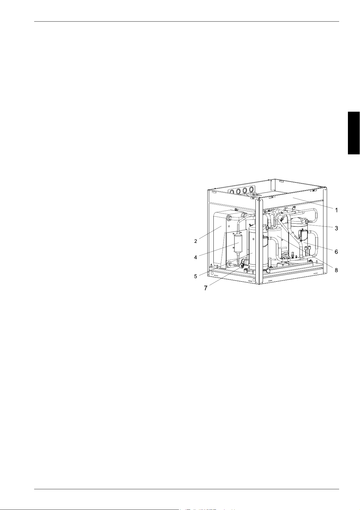
1) Switch box
2) Evaporator
3) Liquefier
4) Filter dryer
5) Compressor 1
6) Compressor 2
7) Expansion valve
8) Economiser
Loading ...
Loading ...
Loading ...