Loading ...
Loading ...
Page 3 of 6
201027
ASSEMBLY INSTRUCTIONS (continued)
OPERATION
5. Connect the cable from solar
panel (D) to the bottom of light
fixture (A). Only use solar panel
(D) to charge the light, other
external charger may damage
the light fixture.
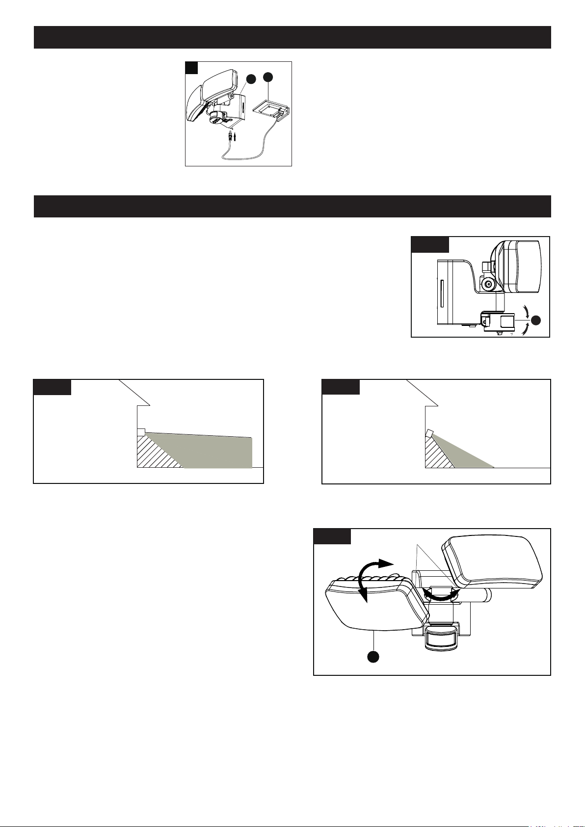
Adjusting the Sensor Head (C):
1. Aim sensor head toward desired detection area, maintaining a 5° - 40° downward
angle to allow moisture to drain.
Note: Make sure sensor head is positioned with controls facing toward the ground.
2. You can rotate the sensor head up and down to change the coverage area.
(See Fig. 1)
Note: Range set too high may increase false triggering.
(See Fig. 2 and Fig. 3)
5
D
A
C
Fig.1
Sensor Adjustment Higher For Long Coverage
Fig. 2
Sensor Adjustment Lower For Short Coverage
Fig. 3
Adjusting the Light Head (B):
1. Adjust the light head up or down, left or right for desired area.
Keep the light heads at least 1˝ (25mm) away from the
sensor.(See Fig. 4)
2. Keep the light heads (B) face down around 30 degrees
angle to avoid water damage and electrical shock.
Axis
B
Fig. 4
Loading ...
Loading ...
Loading ...