Loading ...
Loading ...
Loading ...
Page 18
Installation and Operation Manual - Escape 1200
ENGLISH
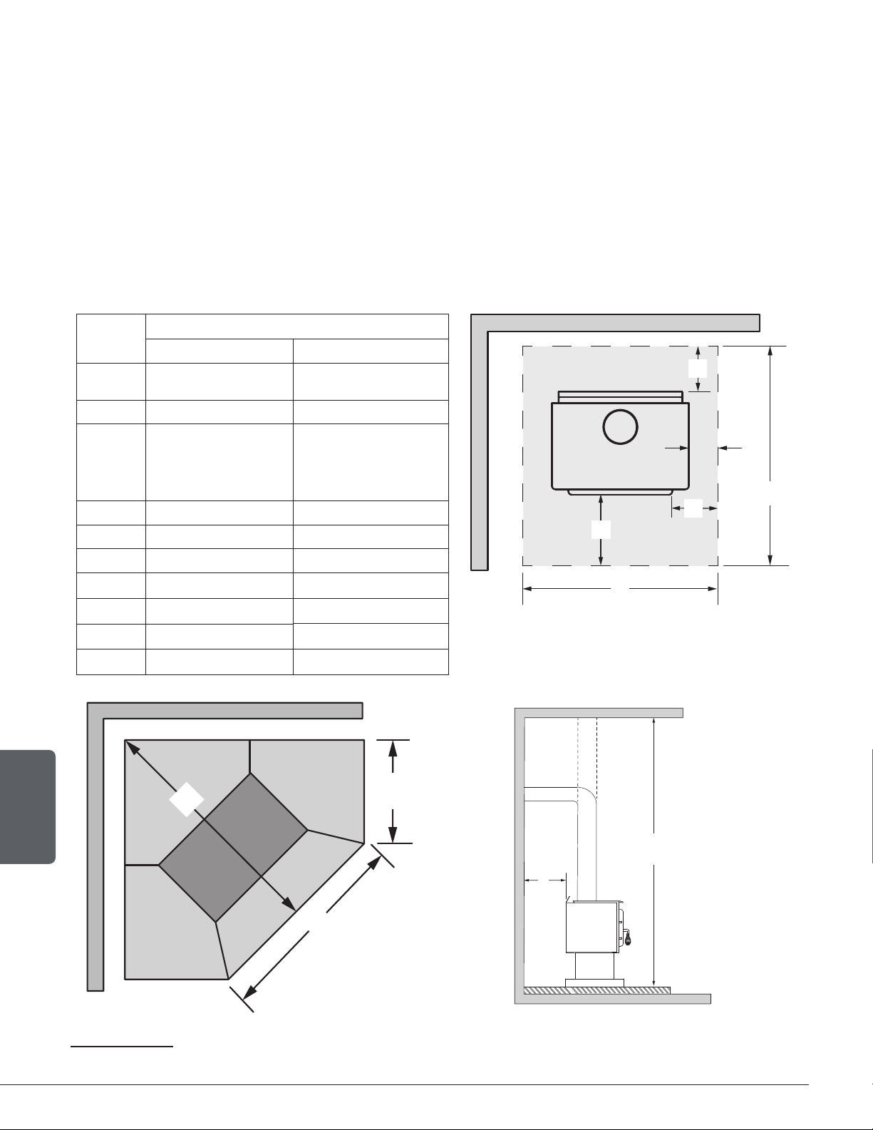
4. Floor Protection
This stove is designed to prevent the floor from overheating. However, it must be placed on a
non-flammable surface to protect the floor from hot embers that may fall during loading.
The floor protection must be a continuous, non combustible material, such as steel with a minimum
thickness of 0.015" (0.38 mm) or ceramic tiles sealed together with grout. Cement board, brick, or
any other approved or listed material suited for floor protection. No R factor required.
Any type of tile will require a continuous non combustible sheet beneath to prevent the possibility
of embers falling through to the combustible floor if cracks or separation should occur in the
finished surface. Check local codes for approved alternatives.
No protection is required if the unit is installed on a non-combustible floor (ex: concrete).
FLOOR PROTECTION
Canada USA
G
21
8" (203 mm) N/A
H 8" (203 mm) N/A
I 18" (457 mm)
From door
opening
16" (203 mm) From
door opening
J N/A 8" (203 mm)
K 34 ½" (876 mm) 31 ¼ (794 mm)
N
22
N/A See note 22
S 48 ¾" (1238 mm) 38 ¾" (984 mm)
T 34 ½" (876 mm) 27 ½" (698 mm)
U 34 ½" (876 mm) 31 ¼ (794 mm)
V 66" (1676 mm) 54 3/8" (1381 mm)
H
I
G
J
K
S
Figure 10: Floor Protection
U
T
V
84"
213 cm
Ve
Ho
N
21
The oor protection at the back of the stove is limited to the stove’s required clearance if such clearance is smaller than 8 inches (203 mm).
22
Only required under the horizontal section (Ho) of the connector. Must exceed each side of the connector by at least 2 inches (51 mm).
Loading ...
Loading ...
Loading ...