Loading ...
Loading ...
Loading ...
14
CARE AND USE/INSTALLATION
Your beverage dispenser comes equipped with a 5 pound
gas tank and a dual gauge regulator. The lower gauge
should be reading approximately 750 psi (52 bar) when the
tank is properly lled and the tank is not in the refrigerator
(at room temperature). The tank will read less when chilled.
Use this lower gauge as an indicator of how much gas you
have left in the tank.
The upper gauge reads the pressure being supplied to the
beverage keg. Follow the procedure below to adjust the
pressure :
12-14 psi for lager beer
9-12 psi for ale's
3-8 psi for still wines
20-40 psi for sparkling wines
1. Close the shuto valves at the bottom of the regulator.
2. Be sure the faucet handle is closed on the tower (see
Figure 30).
3. Loosen the lock nut by turning counterclockwise us-
ing the
1
⁄2" open end wrench until loose, this will allow
adjustment of the pressure adjustment screw.
4. With the at bladed screwdriver turn the adjustment
screw clockwise to increase the pressure or counter-
clockwise to decrease the pressure.
5. Open the shuto valve on the bottom of the regula-
tor. The gauge reading may drop but will return very
quickly.
6. Pull the ring on the keg coupler to allow the gas to ow
momentarily.
7. Make any ne adjustments if necessary with the adjust-
ment screw.
8. Tighten the locknut with the
1
⁄2" open end wrench by
turning clockwise.
Your beverage dispenser comes equipped with a 5 pound
gas tank and a single gauge regulator. The gauge reads the
pressure being supplied to the beverage keg. Follow the
procedure below to adjust the pressure:
12-14 psi for lager beer
9-12 psi for ale's
3-8 psi for still wines
20-40 psi for sparkling wines
1. Close the shuto valve at the bottom of the regulator.
2. Be sure the faucet handle is closed on the tower (see
Figure 30).
3. Loosen the lock nut by turning ↶ counterclockwise us-
ing the
1
⁄2" open end wrench until loose, this will allow
adjustment of the pressure adjustment screw.
4. With the at bladed screwdriver turn the adjustment
screw ↷ clockwise to increase the pressure or ↶ coun-
terclockwise to decrease the pressure.
5. Open the shuto valve on the bottom of the regula-
tor. The gauge reading may drop but will return very
quickly.
6. Pull the ring on the keg coupler to allow the gas to ow
momentarily.
7. Make any ne adjustments if necessary with the adjust-
ment screw.
8. Tighten the locknut with the
1
⁄2" open end wrench by
turning clockwise ↷.
Ring on
keg
coupler
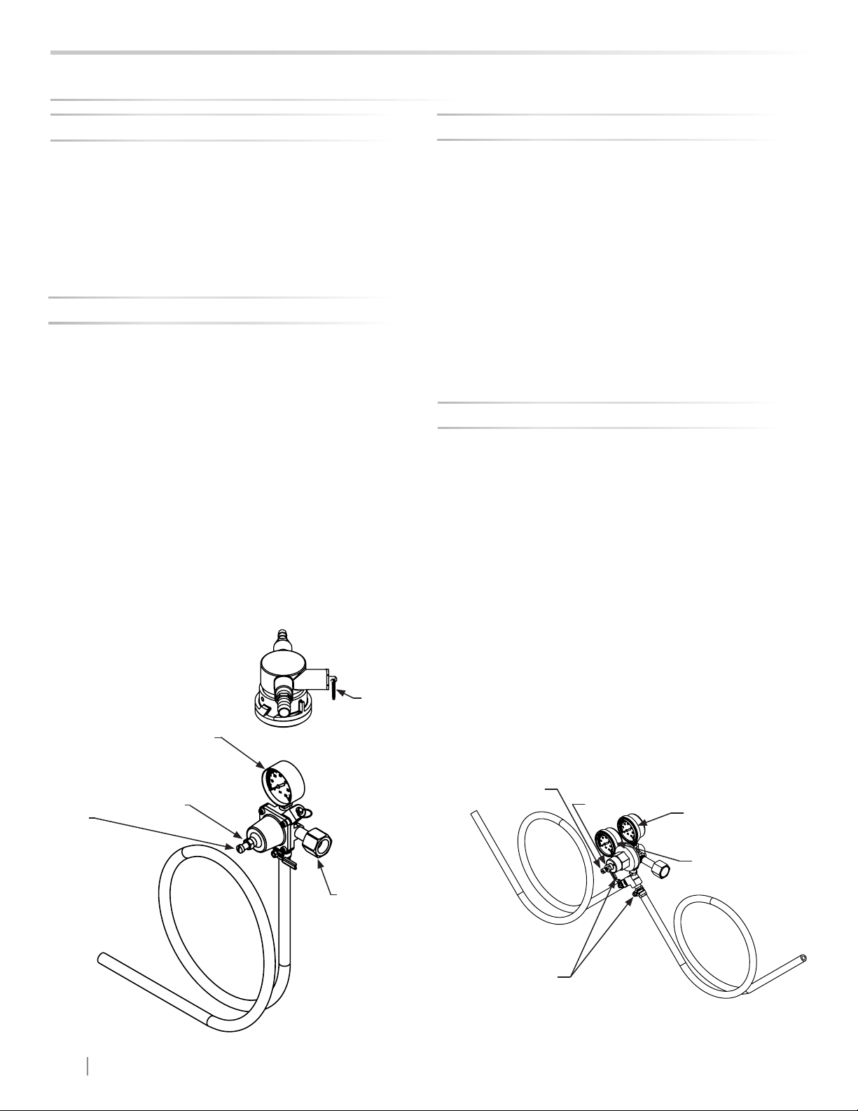
Figure 33
(Regulator for Single
Dispense Tower)
Figure 34
(Regulator for Double
Dispense Tower)
Figure 32
(2) shuto
valves (closed
position shown)
Upper Gauge
Pressure Gauge
Lower Gauge
Pressure
Adjustment
Screw
Lock Nut
USING YOUR BEVERAGE DISPENSER
Pressure
Adjustment
Screw
Lock Nut
shuto valve
(closed posi-
tion shown)
Gas Regulator (Single Dispense Tower)
To adjust the pressure (Single Gauge):
Gas Regulator (Double Dispense Tower)
To adjust the pressure (Upper Gauge):
Loading ...
Loading ...
Loading ...