Loading ...
Loading ...
Loading ...
4
MY996_R (08-20-20)
This submersible sewage pump is designed for effluent and
wastewater removal, sump drainage, dewatering, flood control.
Units have built in thermal overload protection with automatic
reset.
The mechanical seal and bearings on the motor shaft are
permanently lubricated. Stainless steel hardware and a heavy
duty lift out ring allow for easy disassembly after extended use.
NOTE: This unit is not designed for applications involving salt
water or brine! Use with salt water or brine will void warranty.
SPECIFICATIONS
Power supply required..............................................115V, 60 HZ.
Motor Duty................................................................Continuous
Motor HP................................................................................1/2
Individual Branch Circuit Required.................................15 Amps
Liquid Temp. Range.................................32°F to 130°F (0°-55°C)
Cord Length........................................................................10 ft
Discharge Adapter...........................................................2” NPT
PERFORMANCE
INSTALLATION
Install the pump on a hard, level surface (cement, asphalt, etc.).
Never place the pump directly on earth, clay or gravel surfaces.
PIPING
Piping must not be smaller than pump discharge. When
installed in a sewage system, the pipe must be capable of
handling semi-solids of at least 2” (51mm) in diameter.
When installed in an effluent system, the pipe must be
capable of handling semi-solids of at least 3/4” (19mm) in
diameter.
The rate of flow in the discharge pipe must keep any solids
present in suspension in the fluid. To meet minimum flow
requirements (2 feet per second in the discharge line), size
the pipe as follows:
In a sewage system use a 2” (51mm) check valve in pump
discharge to prevent backflow of liquid into sewage basin.
The check valve should be a free flow valve that will easily
pass solids. Be sure check valve installation complies with
local codes.
In an effluent system use a 1-1/2” (38mm) check valve in
pump discharge to prevent backflow of liquid into sewage
basin. The check valve should be a free flow valve that will
easily pass solids. Be sure check valve installation complies
with local codes.
For best performance of check valve when handling solids,
do not install it with the discharge more than 45° above
the horizontal. Do not install the check valve in a vertical
position as solids may settle in the valve and prevent it from
opening on startup.
Drill a 3/16” (5mm) hole in the discharge pipe about 1–2”
(25-51mm) above the pump discharge connection (but below
check valve) to prevent airlocking the pump.
INSTALLATION
A PIPE SIZE OF: WILL HANDLE A FLOW RATE OF:
1-1/2” (38mm) 12 GPM
2” (51mm) 21 GPM
2-1/2”(64mm) 30 GPM
3”(76mm) 48 GPM
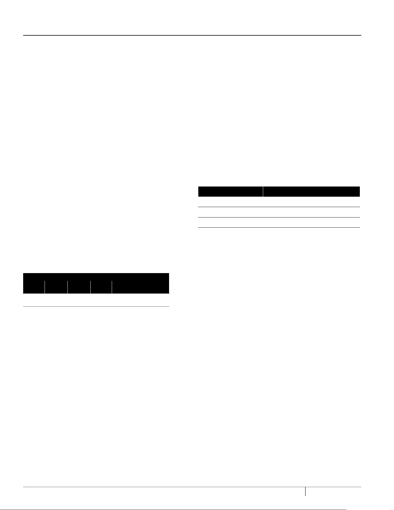
GPH (LPH) AT TOTAL FEET (M) OF LIFT
0'
(0m)
5'
(1.5m)
10'
(3.0M)
15'
(4.6M)
NO FLOW AT HEIGHT SHOWN
BELOW IN FEET (METERS)
9000
(34069)
7200
(27255)
5400
(20441)
3000
(11356)
18' (5.5)
Loading ...
Loading ...
Loading ...