Loading ...
Loading ...
Loading ...
For parts or assistance, call Simer Customer Service at 800-468-7867
4. Install discharge plumbing. Use rigid plastic pipe and
wrap threads with
PTFE pipe thread sealant tape
.
Hand tighten pipe into pump plus 1-1/2 turns.
Risk of flooding. Can cause personal injury
and/or property damage. If a flexible discharge hose is
used, make sure pump is secured in sump to prevent
movement. Failure to secure pump may allow pump
movement, switch interference and prevent pump from
starting or stopping.
5. To reduce motor noise and vibrations, a short length
of rubber hose (1-7/8” (47.6mm) I.D., e.g. radiator
hose) can be connected into discharge line near pump
using suitable clamps.
6. Install an in-line check valve or an in-pump check
valve to prevent flow backwards through pump when
pump shuts off.
NOTICE If your check valve is not equipped with an
air bleed hole to prevent airlocking pump, drill a 1/8”
(3.2 mm) hole in discharge pipe just above where the
discharge pipe screws into the pump discharge. Be sure
the hole is below the waterline and the check valve to
prevent air locks.
7. Power Supply: Pump is designed for 115 V., 60 Hz.,
operation and requires a minimum 15 amp individual
branch circuit. Both pump and switch are supplied
with 3-wire cord sets with grounding-type plugs.
Switch plug is inserted directly into outlet and pump
plug inserts into opposite end of switch plug.
Risk of electric shock. Can shock, burn or
kill. Pump should always be electrically grounded to a
suitable electrical ground such as a grounded water pipe
or a properly grounded metallic raceway, or ground wire
system. Do not cut off round ground pin.
8. If pump discharge line is exposed to sub-freezing
weather conditions, portion of exposed pipe must
be installed so any water remaining will drain out or
down due to gravity. Failure to do this can cause water
trapped in discharge to freeze which could result in
damage to pump.
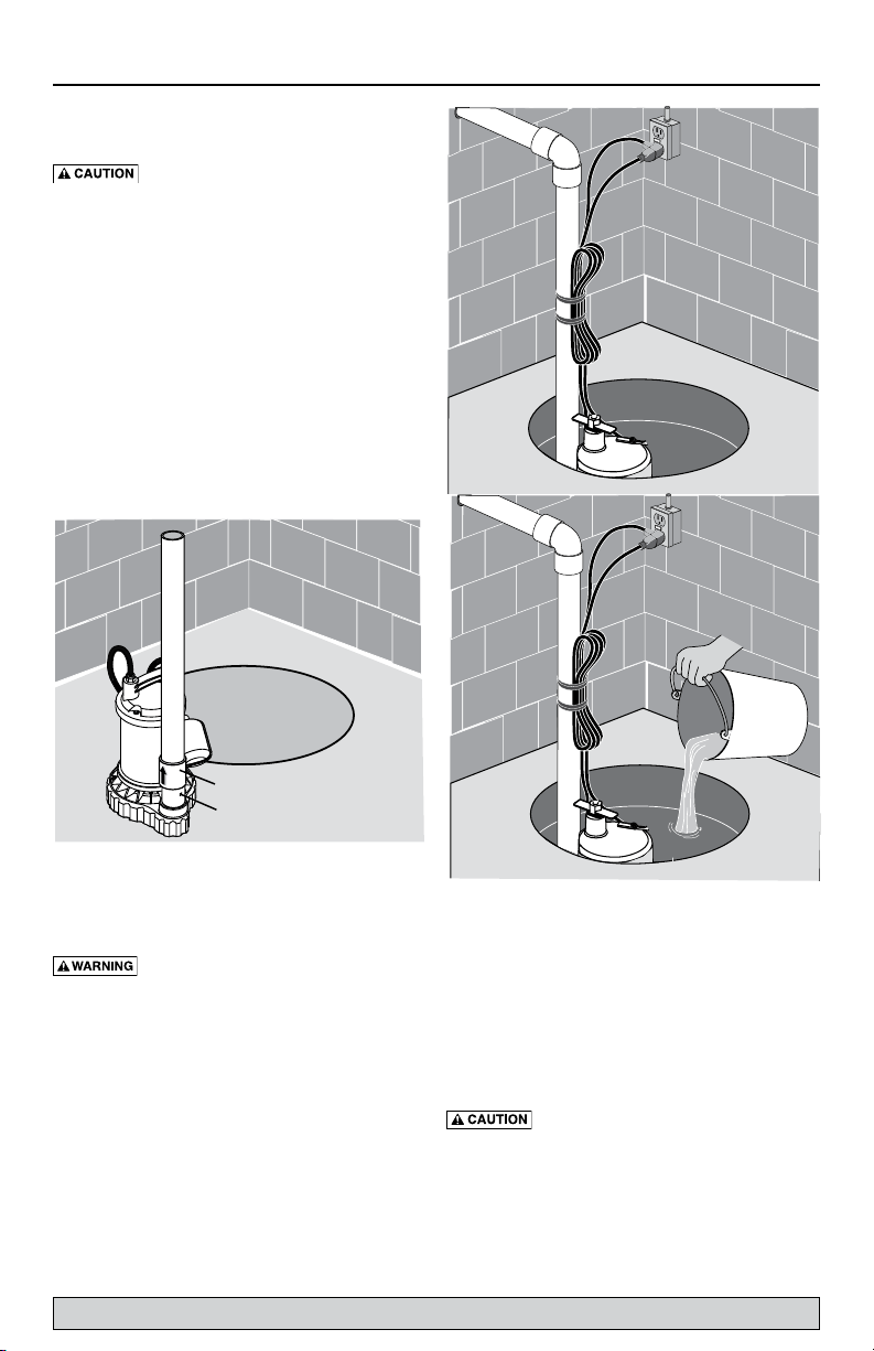
9. After piping, check valve and float switch have been
installed, the unit is ready for operation.
10. Check the pump operation by filling sump with water
and observing pump operation through one complete
cycle. For switch settings see the Electrical and Switch
Specifications chart on Page 2.
Risk of flooding. Can cause personal injury
and/or property damage. Failure to make this operational
check may lead to improper operation, premature failure,
and flooding.
Operation 4
Check valve
Air lock hole
6615 0712
6616 0712
Loading ...
Loading ...
Loading ...