W10772547A
BUILT-IN OVEN MICROWAVE SAFETY .................................. 1
INSTALLATION REQUIREMENTS .......................................... 2
Tools and Parts .................................................................... 2
Location Requirements ....................................................... 2
Minimum Dimensions .......................................................... 3
Product Dimensions ............................................................. 4
Electrical Requirements ........................................................ 5
INSTALLATION INSTRUCTIONS ............................................ 6
Install the Microwave Oven
(24" [61.0 cm] Installation Only) ............................................ 6
Install the Microwave Oven
(27" [68.6 cm] or 30" [76.2 cm] Installation Only) ................. 7
Complete Installation ............................................................ 8
ASSISTANCE .......................................................................... 8
Table of Contents
This product is suitable for use above electric or gas built-in ovens, and below non-vented electric or gas cooktops. This product
is not suitable for use below downdraft cooktops.
These Installation Instructions cover different models. The appearance of your particular model may differ slightly from
the illustrations in these Installation Instructions.
BUILT-IN MICROWAVE OVEN
INSTALLATION INSTRUCTIONS
24" (61.0 cm), 27" (68.6 cm), 30" (76.2 cm)
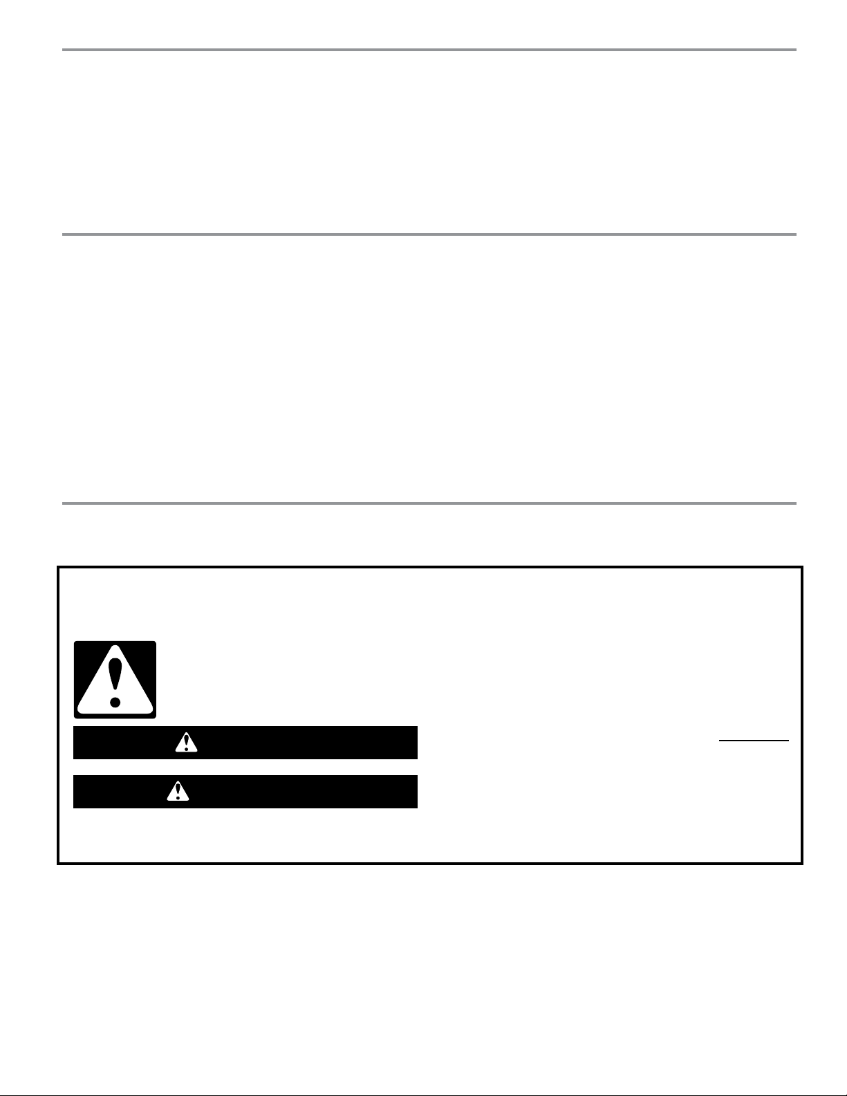
BUILT-IN MICROWAVE OVEN SAFETY
You can be killed or seriously injured if you don't immediately
You
can be killed or seriously injured if you don't
follow
All safety messages will tell you what the potential hazard is, tell you how to reduce the chance of injury, and tell you what can
happen if the instructions are not followed.
Your safety and the safety of others are very important.
We have provided many important safety messages in this manual and on your appliance. Always read and obey all safety
messages.
This is the safety alert symbol.
This symbol alerts you to potential hazards that can kill or hurt you and others.
All safety messages will follow the safety alert symbol and either the word “DANGER” or “WARNING.”
These words mean:
follow instructions.
instructions.
DANGER
WARNING
2
INSTALLATION REQUIREMENTS
Tools and Parts
Tools Needed
Gather the required tools and parts before starting installation.
Read and follow the instructions provided with any tools
listed here:
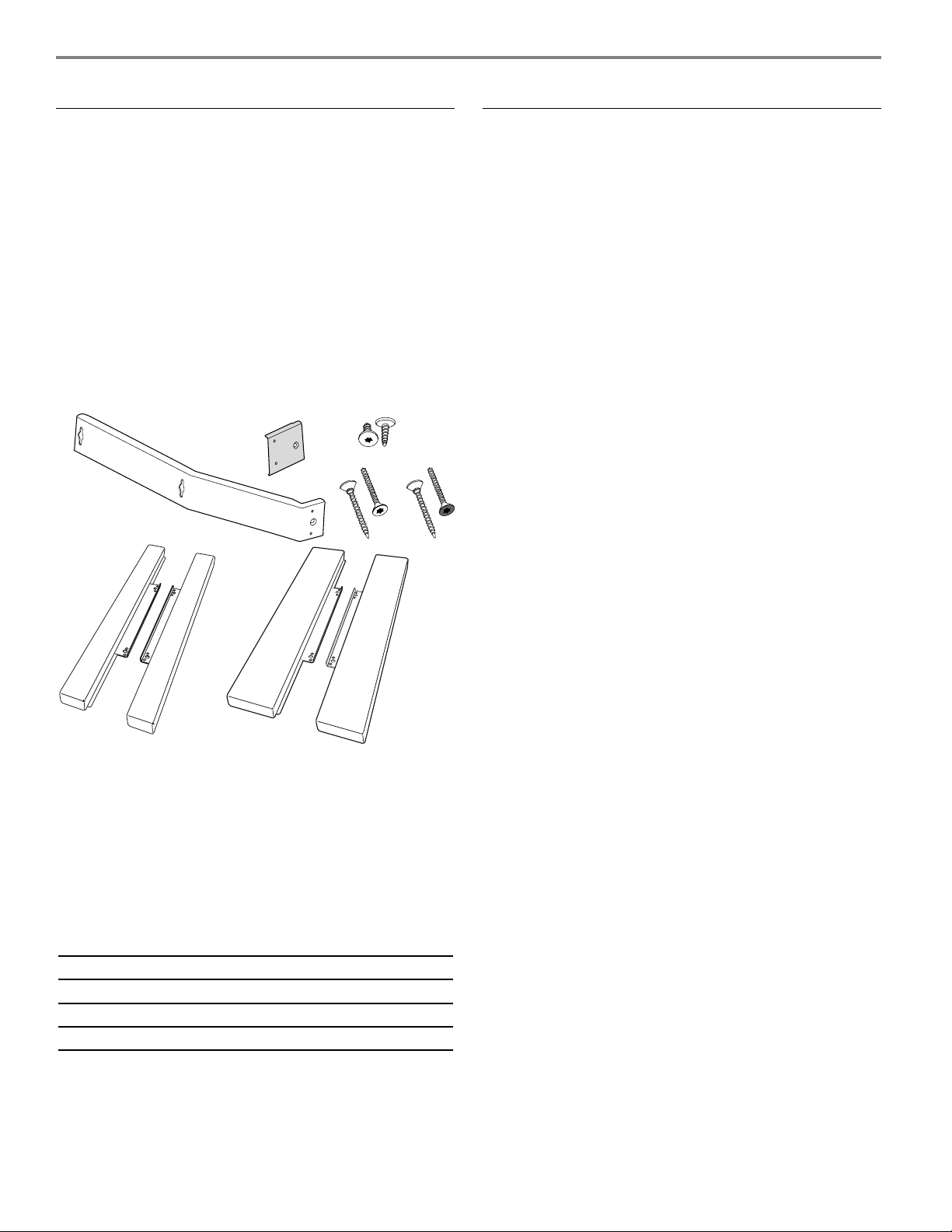
Parts Supplied
All of the following parts are provided, but not all parts will
be used. The cutout opening size will determine which parts
you will use. See chart below parts list to see which parts are
used for each installation.
Location Requirements
The microwave oven may be located in a cabinet, and/or above
a built-in oven, or below the counter and/or below a non-vented
cooktop. Check the opening where the microwave oven will
be installed. The location must provide:
■ Wood cabinetry.
■ Cutout opening that is plumb and square. See “Minimum
Cutout Dimensions” in “Minimum Dimensions” section.
■ Cutout floor that is solid, level, and flush with bottom
of cabinet cutout.
■ Support for weight of at least 150 lbs (68 kg), which includes
microwave oven and items placed inside.
■ Grounded electrical outlet. See “Electrical Requirements”
section.
■ Minimum installation clearances for installation location.
See “Minimum Dimensions” section.
■ Complete enclosure around the recessed portion
of the microwave oven.
■ Measuring tape
■ Pencil
■ T10 TORX
®†
screwdriver
■ Drill
■ 5/64" (2 mm) drill bit
A
B
C
D
GF
E
A. Side brackets (2)
B. Extension plates (2)
C. 3/8" T10 screws (4)
D. 1" T10 screws – stainless steel (6)
E. 1" T10 screws – black (4)
F. Narrow side trim panels (2)
G. Wide side trim panels (2)
NOTE: On some models, side brackets (A), extension plates
(B), and 3/8" T10 screws (C) may come pre-assembled.
INSTALLATION PARTS USED
24" (61.0 cm) installation D or E
27" (68.6 cm) installation A, D or E, F
30" (76.2 cm) installation A, B, C, D or E, G
†®TORX is a registered trademark of Acument Intellectual Properties, LLC.
3
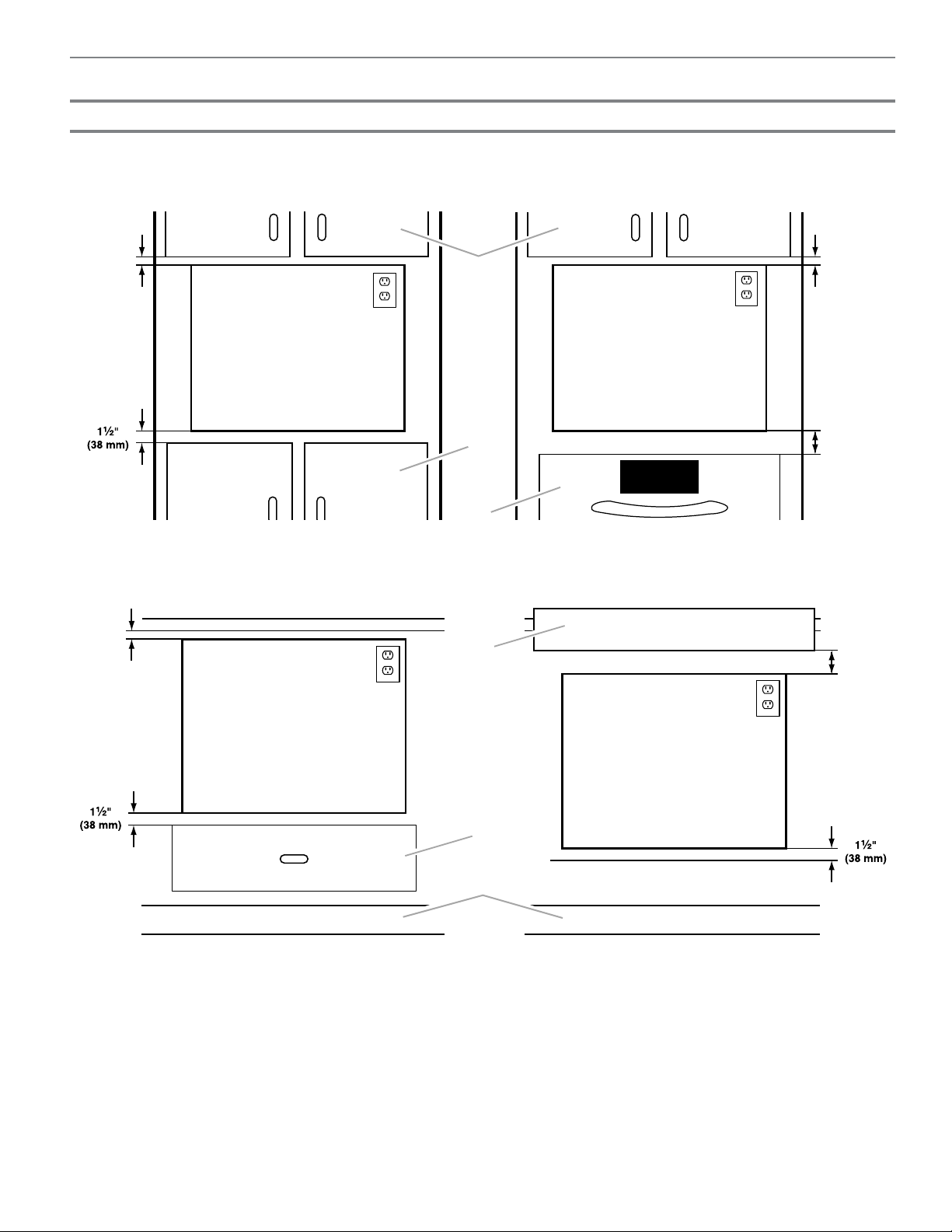
Minimum Dimensions
Minimum Installation Clearances
For proper installation, the following minimum clearances must exist above and below the cutout opening.
Above Cabinet/Storage Drawer Installation Above Oven/Warming Drawer Installation
Below Counter Installation Below Built-in Cooktop Installation
A. Upper cabinet
B. Lower cabinet or storage drawer
C. Lower oven or warming drawer
D. Built-in cooktop (non-vented)
E. Storage drawer
F. Toe kick
NOTE: The bottom of the cooktop may be sunk into the counter and lower cabinet. The minimum 3" (7.6 cm) clearance must
exist below the lowest point of the cooktop, and there must be no interference between any part of the cooktop (including any
gas fittings) and the microwave oven.
1"
(25 mm)
1"
(25 mm)
3"
(76 mm)
A
B
C
1"
(25 mm)
3"
(76 mm)
D
E
F
See note
below.
4
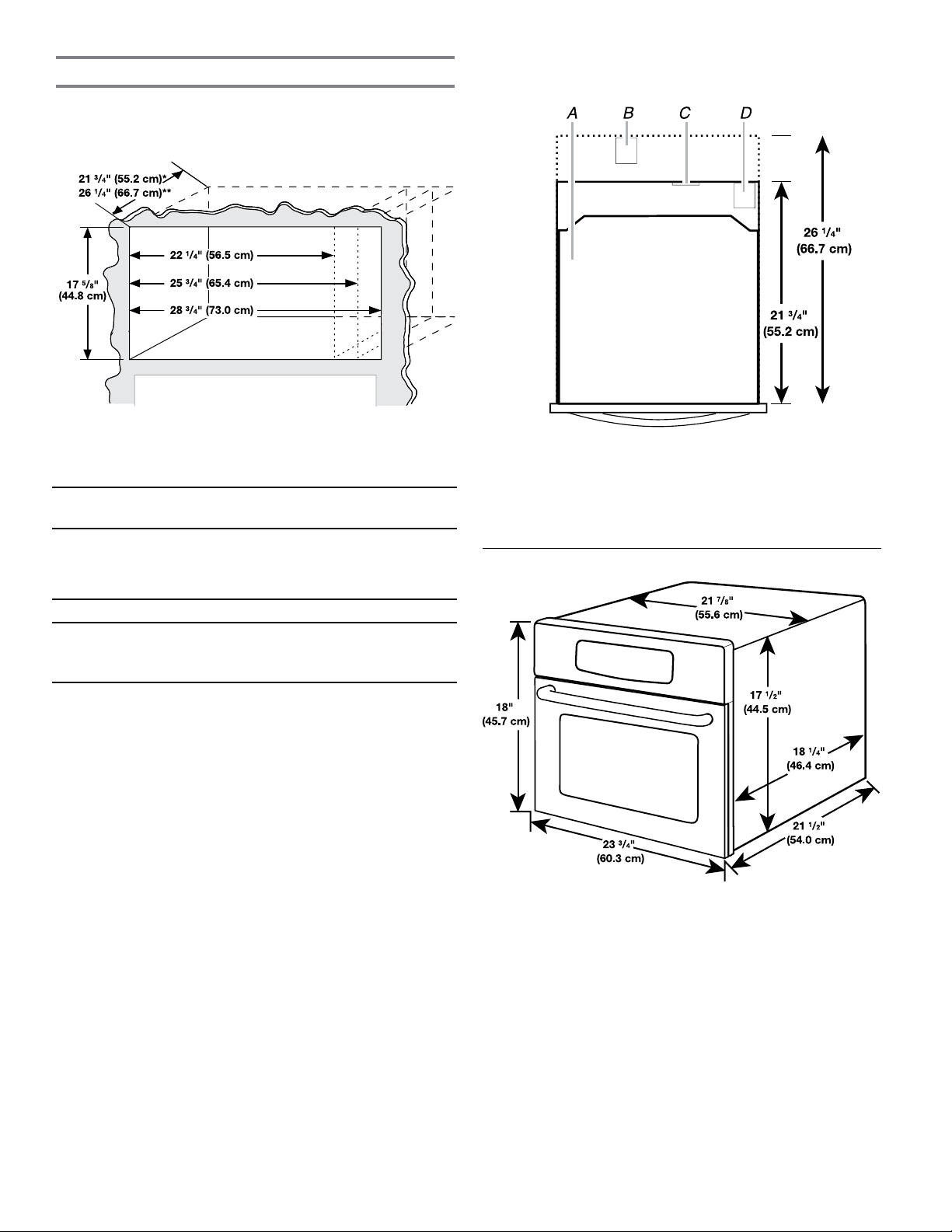
Minimum Cutout Dimensions
NOTE: Depth dimension may be 21
3
/4" (55.2 cm) with non-flush
receptacle only if the receptacle is located in upper right
or upper left corner. See “Cutout Top View”.
* With flush receptacle, or with non-flush receptacle located in
upper right or upper left corner of cutout.
**With non-flush receptacle.
DIM. 24" (61.0 cm)
INSTALLATION
27" (68.6 cm)
INSTALLATION
30" (76.2 cm)
INSTALLATION
Width 22
1
/4"
(56.5 cm)
± 3/16"
(4.8 mm)
25
3
/4"
(65.4 cm)
± 3/16"
(4.8 mm)
Min. 25
3
/4"
(65.4 cm)
Max 28
3
/4"
(73.0 cm)
Height 17
5
/8" (44.8 cm) for all installations
Depth 21
3
/4" (55.2 cm) with flush receptacle, or with
non-flush receptacle located in far corner;
26
1
/4" (66.7 cm) with non-flush receptacle
Cutout Top View
A. Microwave Oven
B. Non-flush receptacle
C. Flush receptacle
D. Non-flush receptacle located in upper right
or upper left corner
Product Dimensions
* Measurements include front facing of microwave oven.
Depth measurement also includes door handle.
5
Electrical Requirements
Observe all governing codes and ordinances.
Required:
A 120 volt, 60 Hz, AC only, 15- or 20-amp electrical supply with
a fuse or circuit breaker.
Recommended:
A time-delay fuse or time-delay circuit breaker.
A separate circuit serving only this microwave oven.
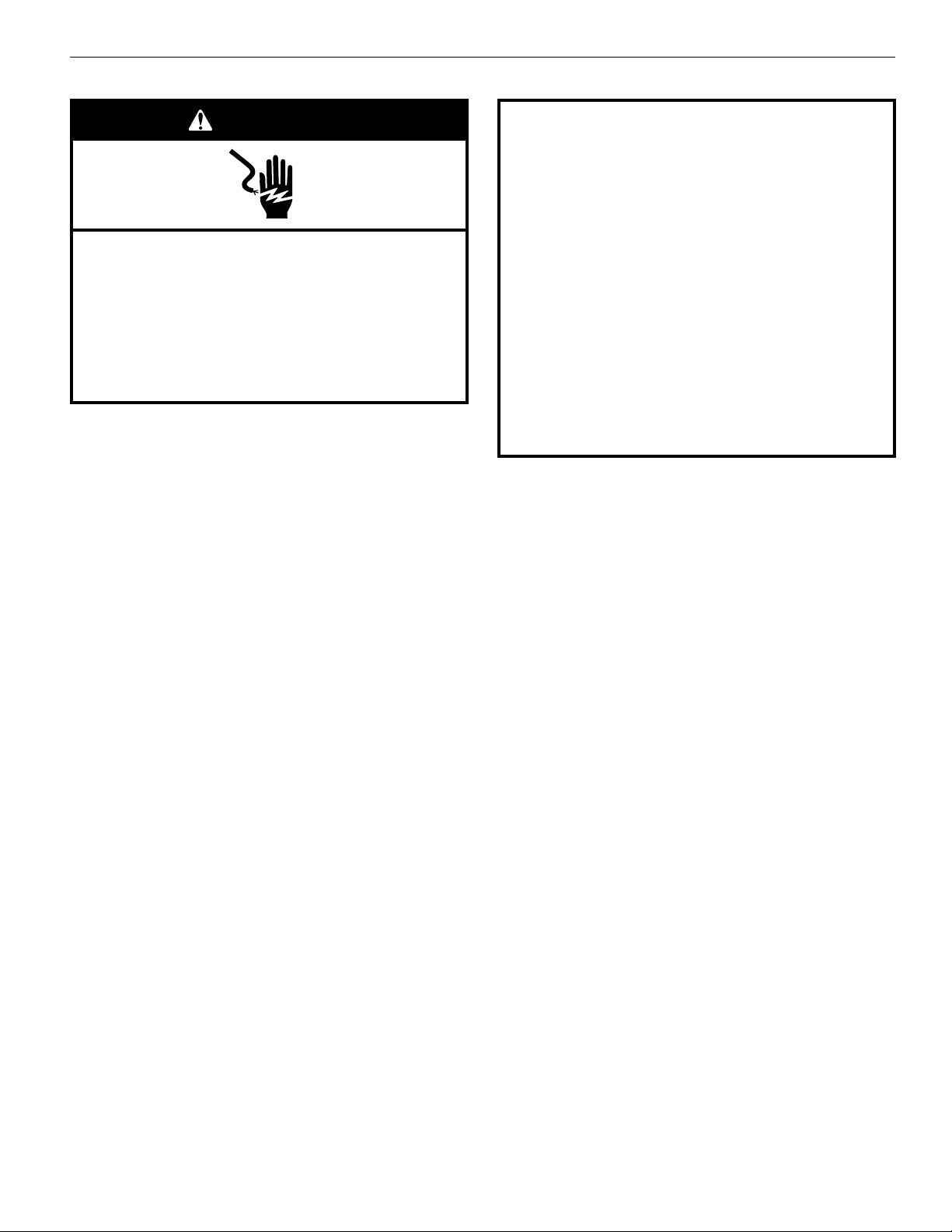
Electrical Shock Hazard
Plug into a grounded 3 prong outlet.
Do not remove ground prong.
Do not use an adapter.
Do not use an extension cord.
Failure to follow these instructions can result in death,
fire, or electrical shock.
WARNING
GROUNDING INSTRUCTIONS
SAVE THESE INSTRUCTIONS
■
For all cord connected appliances:
The microwave oven must be grounded. In the event of
an electrical short circuit, grounding reduces the risk of
electric shock by providing an escape wire for the electric
current. The microwave oven is equipped with a cord
having a grounding wire with a grounding plug. The plug
must be plugged into an outlet that is properly installed
and grounded.
WARNING:
Improper use of the grounding plug can
result in a risk of electric shock. Consult a qualified
electrician or serviceman if the grounding instructions are
not completely understood, or if doubt exists as to whether
the microwave oven is properly grounded.
Do not use an extension cord. If the power supply cord is
too short, have a qualified electrician or serviceman install
an outlet near the microwave oven.
6
INSTALLATION INSTRUCTIONS
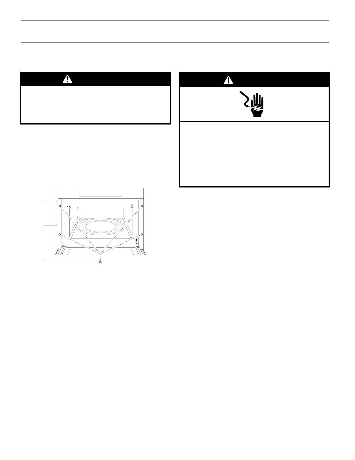
Install the Microwave Oven
(24" (61.0 cm) Installation Only)
NOTE: For this microwave oven, the door handle may be used
for lifting. Do not use any other portion of the control panel,
side brackets, front frame, or trim for lifting.
1. Empty microwave oven of any loose items.
2. Using 2 or more people, slide the microwave oven
all the way into the opening.
3. Center the microwave within the opening.
Open the microwave oven door.
7. With the microwave oven near the opening, plug
the microwave oven into the grounded 3 prong outlet.
8. Replace microwave oven in cutout opening.
9. Open the microwave oven door. The holes in the door
facing frame should align with the holes just drilled into
the cabinet. Fasten the microwave oven door facing to the
cabinet using four 1" T10 screws. Use the black screws for
black models and the stainless steel screws for stainless
steel models.
10. Proceed to “Complete Installation” section.
WARNING
Excessive Weight Hazard
Use two or more people to move and install
microwave oven.
Failure to do so can result in back or other injury.
Electrical Shock Hazard
Plug into a grounded 3 prong outlet.
Do not remove ground prong.
Do not use an adapter.
Do not use an extension cord.
Failure to follow these instructions can result in death,
fire, or electrical shock.
WARNING
A
B
C
4. Mark 4 holes (2 on each side) in the door facing frame
of the microwave oven.
5. To avoid damage to the frame while drilling during the next
step, close the door and remove the microwave oven.
6. Drill the 4 holes using 5/64" (2 mm) drill.
A. Microwave oven door facing frame
B. Cabinet
C. 1" T10 screws (black or stainless steel) (4)
7
Install the Microwave Oven
(27" (68.6 cm) or 30" (76.2 cm) Installation Only)
1. Empty microwave oven of any loose contents.
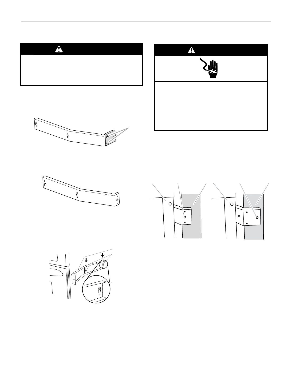
2. For 30" installation, attach the extension plate to each
of the side brackets using two 3/8" T10 screws, as shown.
On some models, the extension plates and side brackets
may come pre-assembled.
7. With the microwave oven near the opening, plug
the microwave oven into the grounded 3 prong outlet.
8. Using 2 or more people, slide microwave oven all
the way into the opening, and center the microwave oven
within the opening.
NOTE: The screw holes on the winged ends of both side
brackets (or extension plates for the 30" installation) must
be fully over the wood of the wall or cabinet, as shown.
A. Side bracket
B. Existing screws (middle and rear)
C. Proper side bracket attachment
A. Door front facing
B. Screw hole for cabinet attachement
C. Cabinet front
WARNING
Excessive Weight Hazard
Use two or more people to move and install
microwave oven.
Failure to do so can result in back or other injury.
Electrical Shock Hazard
Plug into a grounded 3 prong outlet.
Do not remove ground prong.
Do not use an adapter.
Do not use an extension cord.
Failure to follow these instructions can result in death,
fire, or electrical shock.
WARNING
A
B
C
A B C
A
For 27" installation, remove the extension plate from each
of the side brackets by removing the 2 screws, if it came
pre-assembled.
A. 3/8" T10 screws
3. Loosen the middle and rear screws on each side
of microwave oven. The screws are located at the same
height as the door handle.
4. Place the side bracket over the 2 screws, fitting the screw
heads through the keyholes on the bracket. Then slide
the side bracket down so that the upper portions
of the keyholes rest on the screws.
5. Tighten screws to secure the side bracket
to the microwave oven.
6. Repeat steps 4 and 5 on the other side
of the microwave oven.
9. Using 5/64" (2 mm) drill, drill pilot holes into the cabinet
through the screw holes on the side brackets
(or extension plates for the 30" installation).
10. Install two stainless steel 1" T10 screws in the pilot holes
to secure the microwave oven in place.
NOTE: To ensure proper side trim panel fitting, do not
overtighten screws.
11. Open microwave oven door.
A B C
For 27" Installation For 30" Installation
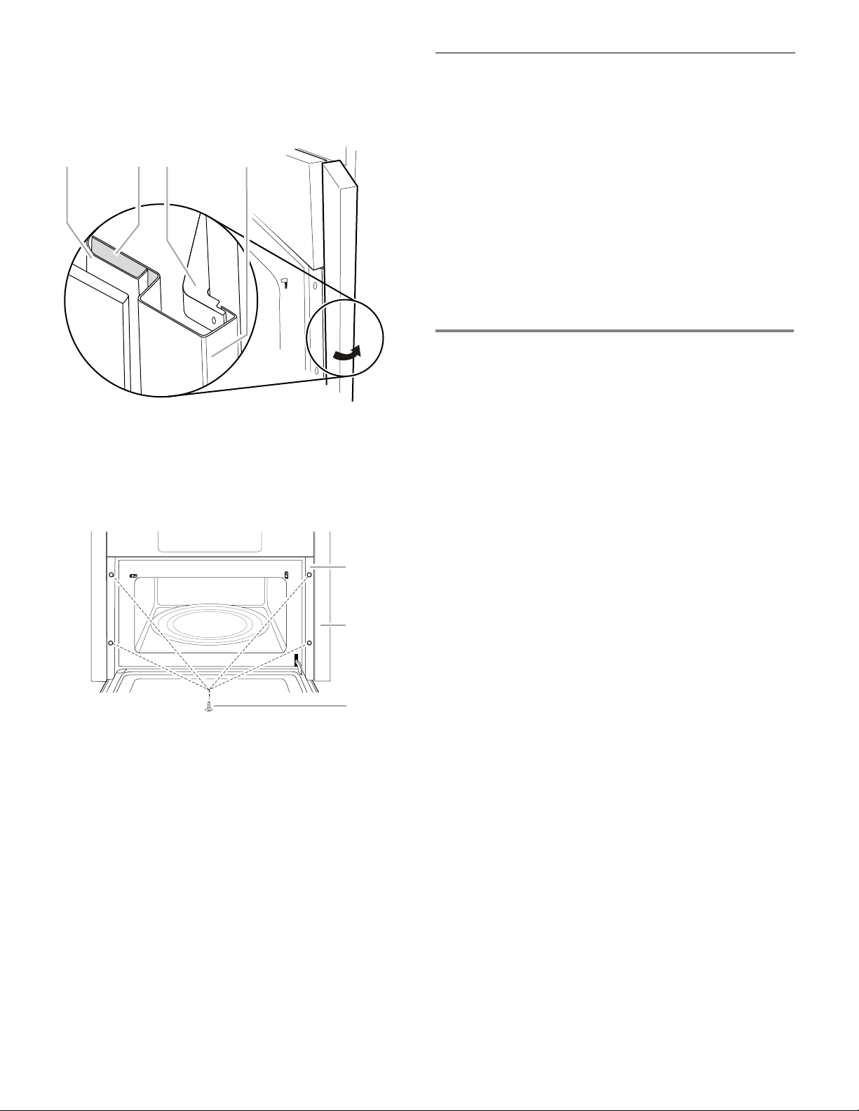
12. Position the tabular portion of the side trim panel behind
the door facing frame, and then firmly push the outside
edge of the trim behind the side bracket, as shown.
Exploded View of Panel Placement
A. Door facing frame
B. Tabular portion (shaded) of side trim panel
C. Side bracket
D. Side trim panel in place
A. Door facing frame
B. Trim panel
C. 1" T10 screws (black or stainless steel) (4)
Complete Installation
1. Install the turntable in the microwave oven.
2. Check the operation of microwave oven by placing 1 cup
(250 mL) of water on the turntable and programming cook
time of 1 minute at 100% power.
3. If the microwave oven does not operate:
■ Check that a household fuse has not blown, or a circuit
breaker tripped. Replace the fuse or reset the curcuit
breaker. If the problem continues, call an electrician.
■ Check that the power supply cord is plugged
into a grounded 3-prong outlet.
■ See the Use and Care Guide for troubleshooting
information.
Installation is now complete.
Save these Installation Instructions for future use.
ASSISTANCE
Call your authorized dealer or service center. When you call,
you will need the microwave oven model number and serial
number. Both numbers can be found on the model and serial
number plate, which is located behind the microwave oven
door on the front frame of the microwave oven.
If you need additional assistance, call us at our toll free number
or visit our website listed in the Use and Care Guide.
W10772547A
SP PN W10775971
A B C
D
A
B
C
© 2015
All rights reserved.
13. Attach the side trim panel to the door facing frame using
two 1" T10 screws. Use the black screws for black models
and the stainless steel screws for stainless steel models.
14. Repeat steps 12 and 13 on other side.
2/15
Printed in U.S.A.