Loading ...
Loading ...
Loading ...
INSTALLATION INSTRUCTIONS (continued)
C
B
A
C
B
A
OFF
LOW
Figure 12
Figure 13
Figure 14
MULTI-WATT BASEBOARD WIRING ON LEFT SIDE
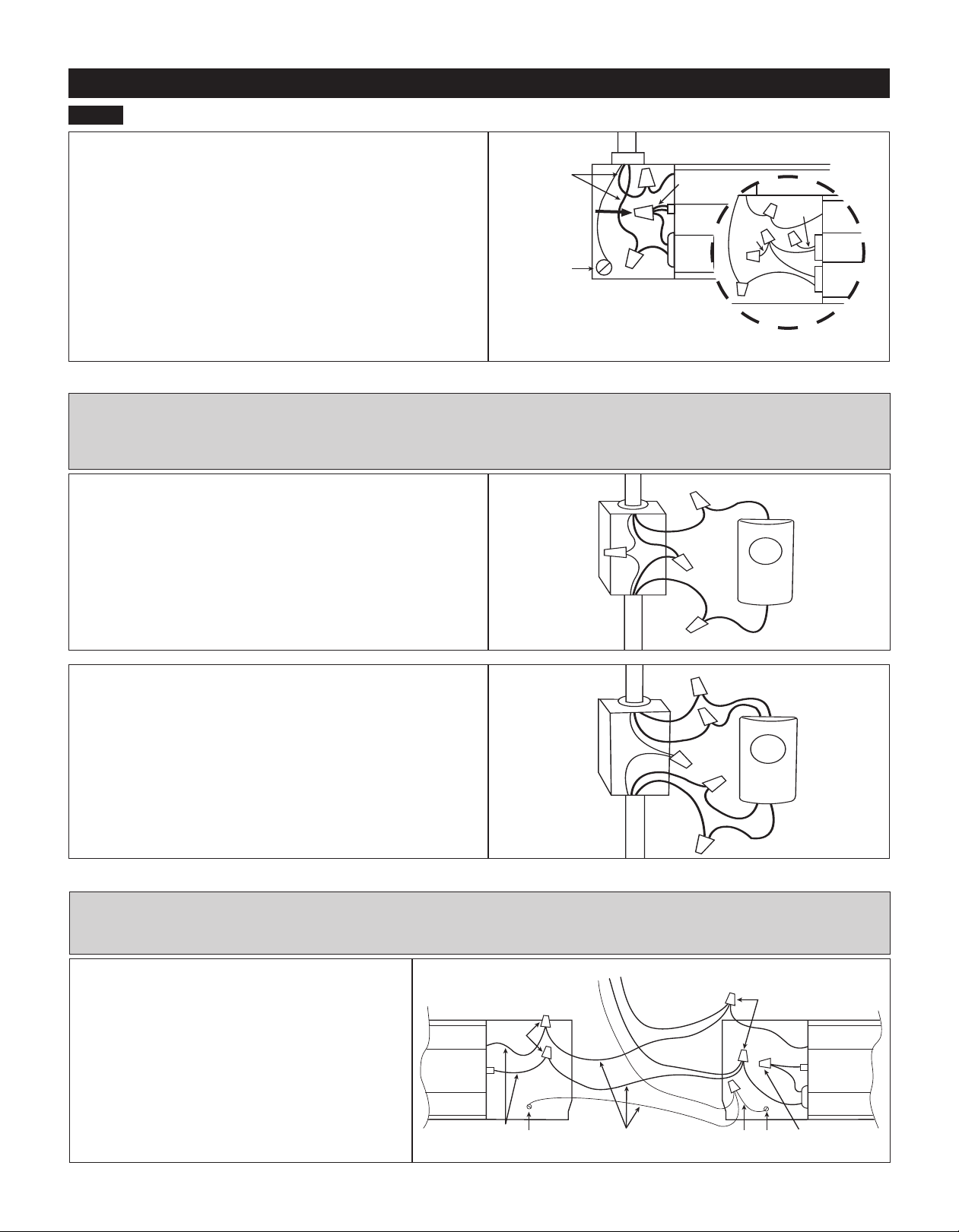
MODEL 8F2025 ONLY (See Figure 11)
1. Disconnect splice/wire connector without the red wire.
2. Connect one supply wire to the upper black wire.
3. Connect the other supply wire to the lower black wire.
4. Selecting desired wattage:
a. For 2500 watt applications: No action is required. Heater is
factory set for 2500 watts.
b. For 2000 watt applications (inset): Cut red wire and cap both
loose ends with an approved wire connector, or wrap loose ends
with electrical tape. Replace wiring compartment cover and secure
with screw previously removed.
5. Turn power back on at the electrical panel board.
Figure 11
Left Side
Wiring Shown
BASEBOARD WIRING WITH A WALL THERMOSTAT - OPTIONAL
Refer to the wiring diagram below that corresponds to your thermostat application. Note: Wiring diagrams are for reference
only. See wall thermostat instructions included with your thermostat for your specic application.
For instructions on wiring using a built-in thermostat, see Cadet BTF1, BTF2 and SBFT2 Installation Instructions.
STEP 2
Baseboard Wiring (continued)
Single Pole Wall Thermostat (Figure 12)
1. Route supply wires to the thermostat wiring box (if not already
present).
2. Connect one supply wire to one thermostat wire (typically
marked L1).
3. Route remaining thermostat wire (typically marked T1) to the
baseboard heater.
4. Route remaining supply and ground wire to the baseboard
heater.
5. Follow installation instructions for mounting and wiring base-
board heater.
Double Pole Wall Thermostat (Figure 13)
1. Route supply wires to the thermostat wiring box (if not already
present).
2. Connect one supply wire to one thermostat wire (typically
marked L1).
3. Connect remaining supply wire to other thermostat wire (typically
marked L2).
4. Route remaining thermostat wires (typically marked T1 and T2)
to the baseboard heater.
5. Route ground wire to the baseboard heater.
6. Follow installation instructions for mounting and wiring base-
board heater.
MULTIPLE BASEBOARD WIRING. 240V SUPPLY
ONLY (See Figure 14)
1. Left side wiring: disconnect factory connector A.
Right side wiring: disconnect factory connector B.
2. Connect one wire from each heater to one supply
wire.
3. Connect remaining wire from each heater to the
remaining supply wire.
4. Connect supply ground wire to both ground screws
using appropriate guage wire.
Note: Field wiring is not provided
MULTIPLE BASEBOARD WIRING - OPTIONAL
Follow the instructions below if you are wiring more than one heater in parallel on same circuit.
If you are wiring multiple baseboards to one control, it is recommended that you use one control per room.
DO NOT DISCONNECT!
DO NOT
DISCONNECT!
Heater
Wires
Ground
Screw
To Wall Thermostat
Baseboard
Heater Right
Side
B
Baseboard
Heater Left
Side
Field Wiring
Field
Wiring
Ground
Screw
A
Supply Wires
Ground Screw
2000 Watt Conguration
Left Side of Baseboard Shown
red wire
red
wire
To Supply
red
wire
Model 8F2025
Factory set for
2500 Watts
Baseboard Heater
Side A
To Supply
To Supply
To Heater
To Heater
Thermostat
Wiring Box
Thermostat
Wiring Box
Single Pole
Thermostat
Double Pole
Thermostat
L1
L1
L2
T1
T1
T2
Page 5
Loading ...
Loading ...
Loading ...