Loading ...
Loading ...
Loading ...
whl-648 Rev. 000 Rel. 003 Date 3.6.18
18
This appliance is too heavy for one person to lift. It is highly recommended to install the appliance with two people. Use caution as to not
drop the appliance, which could damage the appliance and cause property damage and/or severe personal injury. Verify that the appliance
is properly and securely mounted before leaving unsupervised. Failure to comply with the above and properly mount the appliance could
result in substantial property damage, severe personal injury, or death.
This wall mounting system is not seismic rated and should not be applied as such. Failure to comply with the above and properly mount the
appliance could result in substantial property damage, severe personal injury, or death.
Positioning the Appliance on the Wall
1. Attach the wall bracket on the location where you want to install the appliance. Ensure it is level and on stud (16” centers) before
proceeding.
2. Mark the four drill holes with a pencil or marker. Remove the wall bracket.
3. Drill four (4) holes using a 5/32 drill bit at the marked hole locations.
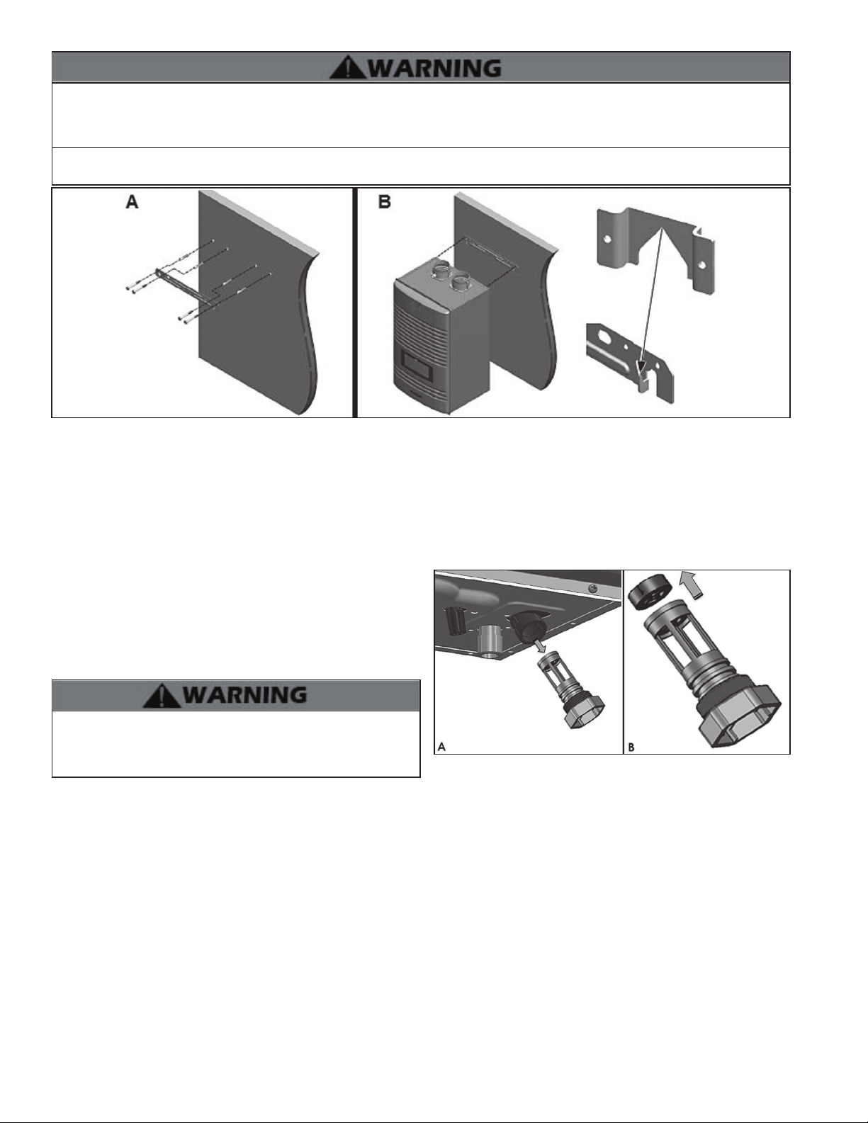
4. Mount the wall bracket to the wall with the four (4) included anchor bolts. Ensure the mounted bracket is level. See Figure 7A.
5. Align the appliance bracket grooves on the back of the appliance with the tongues on the wall bracket and hang the appliance on the
bracket. See Figure 7B.
Figure 6 - Wall-Mounting the Appliance
K. Flow Restrictor
A ow restrictor is installed on this appliance in the DHW inlet adapter
to avoid excessive ow at the faucets. See Flow Charts, this manual, for
more information.
If it is necessary to further increase ow to the system, replace the
factory installed white ow restrictor with the blue included with the
appliance by following the instructions below.
If the appliance is already fully installed, turn the gas, power, and
water o to the appliance and drain all water from the appliance
BEFORE proceeding. Failure to comply could result in substantial
property damage, severe personal injury, or death.
Figure 7 - A - Removing the DHW Inlet Filter, B - Removing the Flow
Restrictor
1. Locate the DHW inlet adapter on the bottom of the appliance.
2. Pull the two pins to release the DHW inlet lter. See Figure 7-A. The ow restrictor is attached to the top of the lter assembly.
3. Remove the installed white ow restrictor and replace it with the blue ow restrictor included with the appliance. See Figure 7-B.
4. Reinstall the DHW inlet lter.
5. Reinstall the two pins.
Loading ...
Loading ...