Loading ...
Loading ...
Loading ...
whl-648 Rev. 000 Rel. 003 Date 3.6.18
15
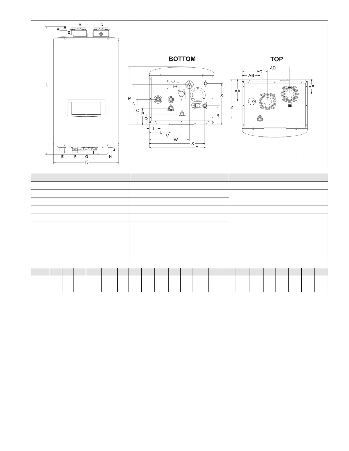
Figure 3 - Wall Mount Model Dimensions
Description Diameter
A Automatic Air Vent -
B Air Intake Adapter
3”
C Exhaust Vent Adapter
D Pressure Relief Valve Adapter 3/4” NPTF
E CH Supply Adapter
1” NPT
F CH Return Adapter
G DHW Outlet Adapter
3/4” NPTH DHW Inlet Adapter
I Gas Inlet Adapter
J Condensate Adapter 1/2” NPT (3/4” PVC Socket on Floor Models)
Table 9 - Adapter Specications - All Models
Model K L M N O P Q R S T U V W X Y Z AA AB AC AD AE
140 17.3 34 15.4
10.6
6.7 4.3 2.8 5.1 11.0 2.3 5.7 8.9
10.8
14.9 15.1 10.5 5.9 2.3 6.8 12.6 3.9
199 19.7 37 16.8 7.8 5.4 4.0 6.3 12.3 2.5 5.9 10.6 16.6 17.0 12.5 7.0 3.2 9.2 15.1 3.7
How the Appliance Operates
Condensing technology intelligently delivers hydronic heating
while maximizing eciency. Outlined below are the features of the
system and how they operate:
Stainless Steel Heat Exchanger - The highly ecient 316L stainless
steel re tube heat exchanger with internal aluminum is designed
to extract all available heat from the combustion process and pass
it into heat transfer uid. The stainless steel construction provides
protection for longer service life. The heat exchanger oers greater
water content, providing lower system pressure and greater overall
system eciency.
10 to 1 Modulating Combustion System - The combustion
system is specially designed to provide very high turn down. This
combustion system will modulate the burner output to very low
levels to match the system demand and achieve better overall
control of the heating system for maximum eciency and reliability.
Control – The integrated control system monitors the system and
responds to internal and external signals to regulate fan speed and
control output. This allows the appliance to deliver only the amount
of heat energy required and nothing more.
The control can be set up to monitor outdoor temperature through
an outdoor sensor to regulate appliance set point temperature,
increasing overall system eciency while providing great comfort. The
system can be further enhanced by installing an indirect water heater
to provide domestic hot water.
The control can regulate the output of multiple appliances through its
cascade system function by establishing one appliance as the master
and the other connected appliances as followers. The master appliance
requires a sensor to provide feedback on set point temperature
in order to adjust heating output from the connected appliances.
Multiple appliance cascaded systems oer greater system turndown
and redundancy.
Electronic LCD Display – The high resolution display allows the user
to monitor appliance functions. The display also provides the means
to program the system parameters to maximize the eciency of the
system design.
Combustion System (Blower – Gas Valve – Mixer – Burner – Spark
Ignition) – The highly ecient spark ignition combustion system uses
a variable speed blower to adjust combustion as the system requires
more or less energy. The negative regulated gas valve provides only
the amount of fuel required to ensure clean combustion. The mixer
accurately regulates the combination of gas and air throughout
Table 10 - Wall Mount Specications and Dimensions
Loading ...
Loading ...
Loading ...