Loading ...
Loading ...
Loading ...
Operating Instructions and Parts Manual
6
ELECTRICAL
Risk of electrical shock. This pump is designed
for indoor installation unless housed and protected from the elements.
Risque de choc électrique! Cette pompe est
conçue pour une utilisation à l'intérieur, sauf si elle est à l'abri et
protégée contre les intempéries.
• This installation must be in accordance with the National Electric
Code and all applicable local codes and ordinances.
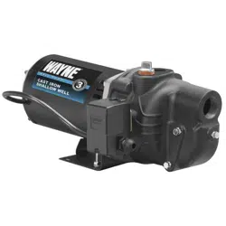
• The voltage of power supply must match the voltage of the
pump. The motors can be converted to 115 or 230 volts by
changing the voltage selector to the desired voltage. Remove
rear cover of motor by unscrewing both screws to expose voltage
selector. Rotate dial so desired voltage is completely visible within
notch (Figure 4).
•If wire run is a short distance, a cord/plug assembly may be
used as long as it meets the minimum wire gage size, called out in
Chart 3, above. Time delay fuses are recommended over standard
fuses for motor circuit protection. All pump motors have built-in
automatic overload protection that will prevent damage to the
motor due to overheating.
• Do NOT connect to electric power supply until unit is
permanently grounded. Connect ground wire to approved ground
then connect terminal provided.
• A metal underground water pipe or well casing at least 10 feet
long makes the best ground electrode. If plastic pipe or insulated
fittings are used, run a wire directly to the metal well casing or use a
ground electrode furnished by the power company.
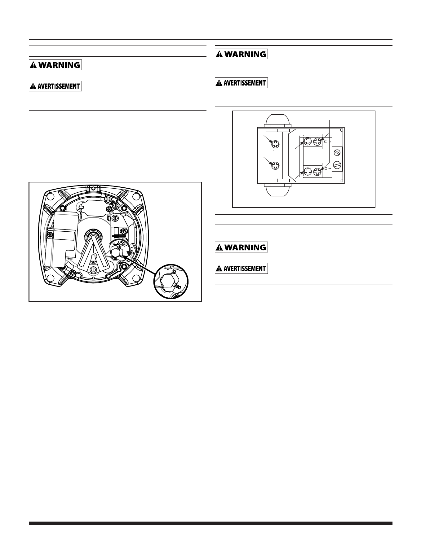
• There is only one proper ground terminal on the unit. The
terminal(s) is located under the pressure switch cover, is painted
green and is identified as GRD. The ground connection must be
made at this terminal (Figure 5). The ground conductor must not be
smaller than the circuit conductors supplying the motor.
Disconnect power and release all pressure from
the system before attempting to install, service, relocate or perform any
maintenance.
Débrancher de la source d’alimentation puis
dissiper toute la pression du système avant d’essayer d’installer, de
réparer, de déplacer ou de procéder à l’entretien.
L2
3
L1
1
Figure 5 - Electrical Connections
MOTOR
LINE
GROUND SCREW
OPERATION
PRIMING THE SHALLOW WELL PUMP
To prevent damage to the pump, do NOT start
motor until pump has been filled with water.
Pour éviter d'endommager la pompe, ne pas
démarrer le moteur tant que la pompe n'a pas été remplie d'eau.
1. Remove prime plug (Figure 3).
2. Fill pump and piping completely full of water.
3. Replace the prime plug.
4. Open a faucet to vent the system.
5. Start the motor. Water will pump in a few minutes. If pump fails
to prime in 5 minutes, stop motor and refill pump with water.
Priming time is proportional to the amount of air in inlet pipe.
6. Let the system operate for several minutes to flush all pipes.
7. Close faucet and allow pump to build pressure in tank. When
the pressure reaches the cut-out setting, the motor will stop.
The system is now in operation and will automatically cycle on
demand.
Figure 4 - Voltage Selector
Loading ...
Loading ...
Loading ...