Loading ...
Loading ...
Loading ...
Page 31
Installation and Operation Manual - Escape 2100
ENGLISH
Any type of tile will require a continuous non combustible sheet beneath to prevent the possibility
of embers falling through to the combustible floor if cracks or separation should occur in the
finished surface. Check local codes for approved alternatives.
No protection is required if the unit is installed on a non-combustible floor (ex: concrete).
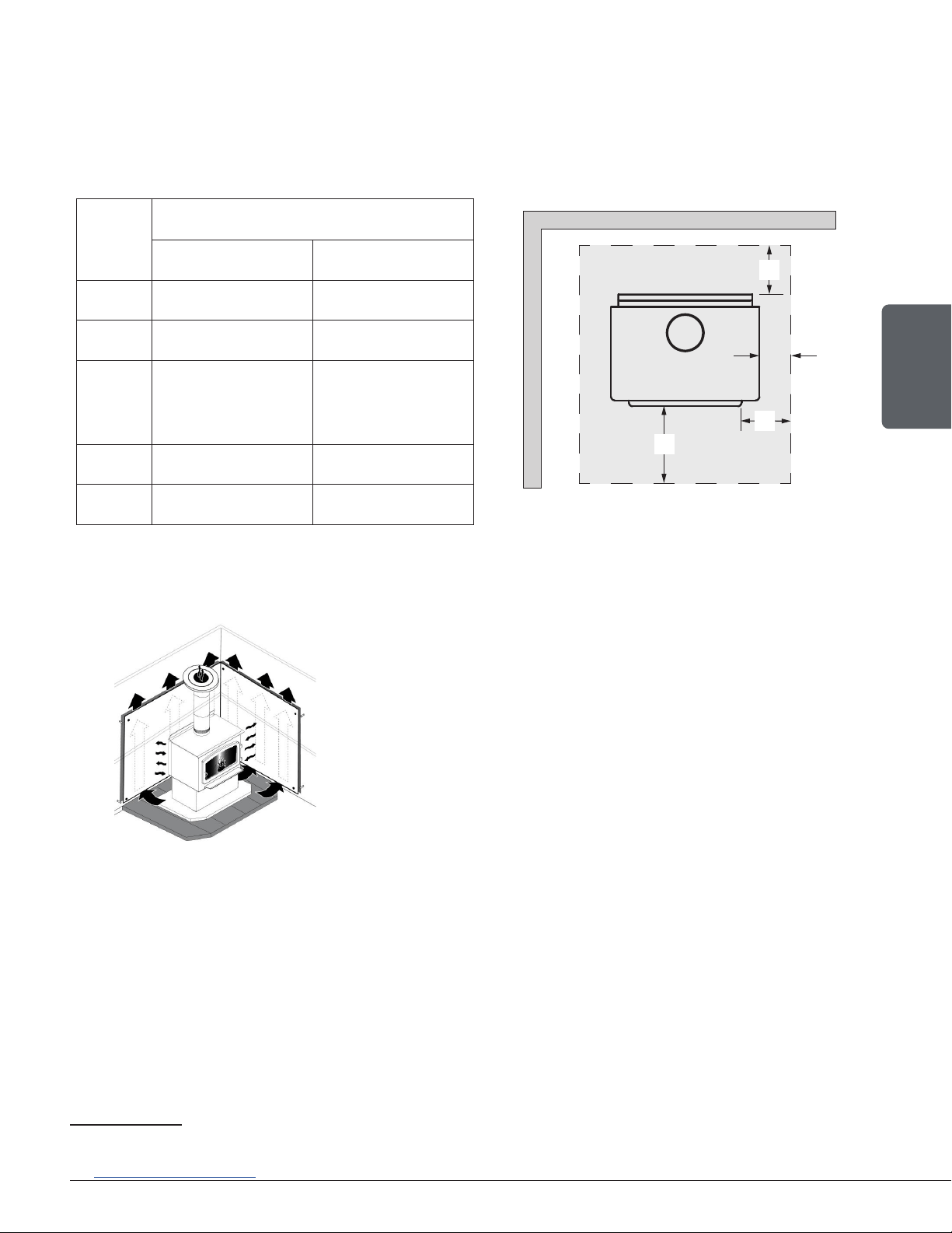
FLOOR PROTECTION
Canada USA
G
18
8" (203 mm) N/A
H 8" (203 mm) N/A
I 18" (457 mm)
From door
opening
16" (203 mm)
From door
opening
J N/A 8" (203 mm)
N N/A See Note 19
H
I
G
J
Figure 12: Floor Protection
8.3 Reducing Clearances Safely
It is often desired to use as little space as possible when
installing a wood stove. To do this, it is possible to reduce the
clearances safely and install the stove closer to the walls by
permanently installing a heat shield between the stove and the
flammable material.
The rules for heat shields are sometimes complicated. Read
and apply the instructions carefully. Some regions may have
different regulations. Consult the local building code or contact
the fire department for restrictions, inspection and installation
requirements in the area.
Warning: Note that to reduce the clearances of an appliance using a single wall pipe connector, the
use of a heat shield certified with the single wall pipe connector to be used as close as 6" from
combustible materials must be used. Only in this case, the same clearances as a certified double wall
pipe connector can be used.
8.3.1 Shield Construction Rules
− Adhesives used in shield construction must not ignite or lose adhesive qualities at temperatures
likely to be encountered.
− Mounting hardware which extends from the shield surface into combustibles may be used only at
the edges of the shield.
− Mounting hardware must allow full vertical ventilation.
18
The oor protection at the back of the stove is limited to the stove’s required clearance if such clearance is smaller than 8 inches (203 mm).
19
Only required under the horizontal section (Ho) of the connector. Must exceed each side of the connector by at least 2 inches (51 mm).
See «Figure 9: Clearances - Side»
Loading ...
Loading ...
Loading ...