Loading ...
Loading ...
Loading ...
Page 8
ASSEMBLY
UNPACKING
This product requires assembly.
• Carefully remove the product and any
accessories from the box. Make sure that
all items listed in the package contents
section are included.
• Inspect the product carefully to make sure
no breakage or damage occurred during
shipping.
• Do not discard the packing material
until you have carefully inspected and
satisfactorily operated the product.
• If any parts are damaged or missing, please
call 1-844-MSTR4CE (844-678-7423) for
assistance.
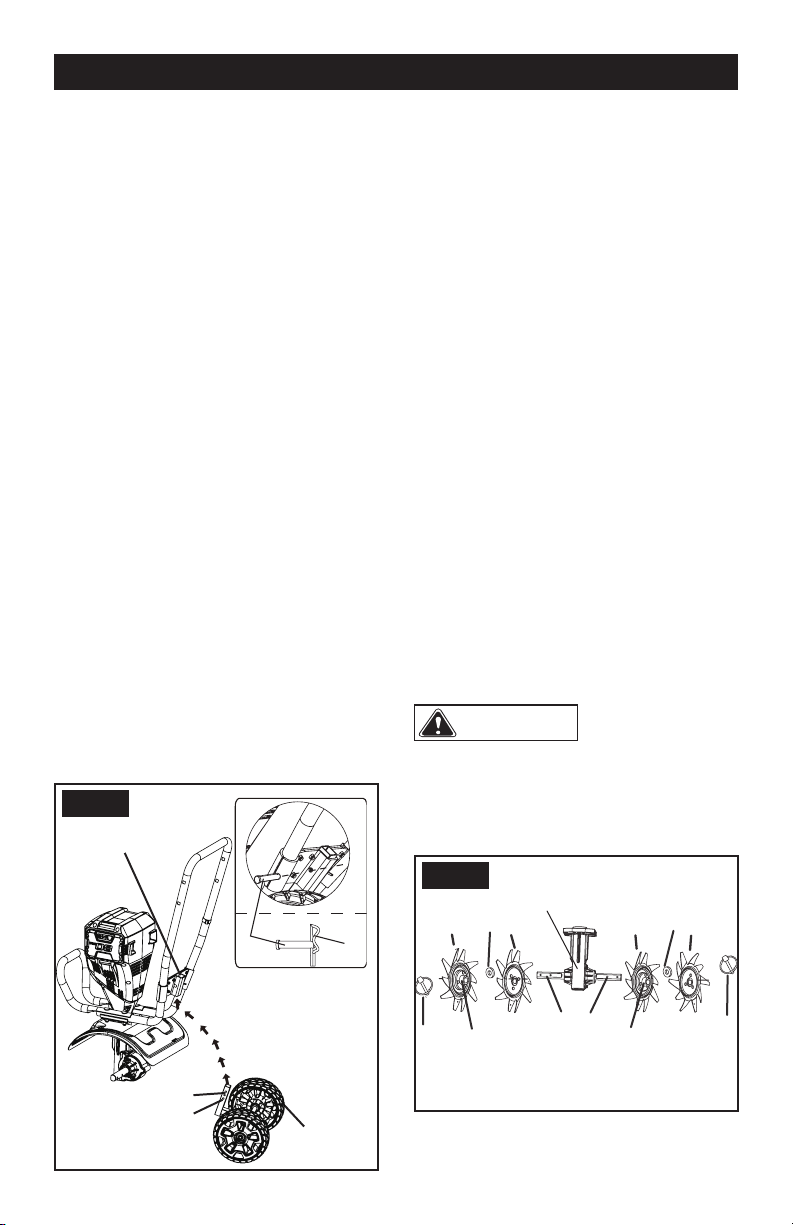
THE WHEELS
1. Remove the battery from the unit.
2. Place cultivator in a stable position as
shown in Fig. 1.
3. Insert the wheel assembly into the support
rod.
4. Align wheel assembly hole to desired
position. Slide bolt through hole and attach
hitch pin to bolt.
5. The highest tilling position is Position A
and lowest tilling position is Position B.
6. Wheels can be removed for greater tilling
depth.
THE TINES
The cultivator has four tines—two inner
tines stamped B and C and two outer tines
stamped A and D. For correct operation of the
unit, the tines must be installed in the correct
orientation.
1. Place tine (C) on the tine shaft to the left of
the gear box. The stamped side of the tine
should face away from the gear box.
2. Place tine (B) on the tine shaft to the right
of the gear box. The stamped side of the
tine should face away from the gear box.
3. Place a felt washer on each side of
the tine shaft, and slide to rest against the
inner tine.
4. Place the outer tine (D) on the left side of
the tine shaft. The stamped side should
face in toward tine (C).
5. Place the outer tine (A) on the right side
of the tine shaft. The stamped side should
face in toward tine (B).
6. To secure the tines to the tine shaft, insert
the hitch pins into the holes located on
either side of the tine shaft.
NOTE:
The unit will not operate properly if
the tines are installed incorrectly. If you notice
a problem with the cultivating operation of the
unit, check for proper tine positioning.
WARNING
The tines and the
machine may damage even if you move the
machine with the motor switched off. To pre-
vent the tines from touching the ground while
moving please tilt the machine.
Support rod
Position A - Highest
Wheel
assembly
Position B - Lowest
Hitch
pin
Step 1
Step 2
Bolt
FIG. 1
Hitch
pin
Hitch
pin
Flute
Flute
Tine(D)
Tine(C)
Gear box
Tine shaft
Tine(B)
Tine(A)
Felt
Felt
FIG. 2
Loading ...
Loading ...
Loading ...