Loading ...
Portable use
WARNING: THE HEATER SHOULD NEVER BE USED AS A PORTABLE
APPLIANCE WITHOUT THE FEET SECURELY FITTED.
WARNING: ONLY THE SCREWS SUPPLIED WITH THIS PRODUCT
SHOULD BE USED TO MOUNT THE FOOT. A MAXIMUM SCREW
LENGTH OF 10MM SHOULD BE USED.
Lay the heater on its back and remove the wall mounting brackets - see
Wall mounting. Locate and remove the foot xing screw - see Fig. 2(a).
Clip the foot in place and secure using the foot xing screw.
NOTE – The wall mounting brackets must be removed before the foot
can be tted.
Wall Mounting (Installed)
Three identical wall mounting brackets are secured to the base of the heater
with a xing screw. To wall mount appliance, rst remove the brackets as
follows, lay the heater on its back and follow the sequence shown - see
Fig. 3. Identify and remove the xing screw securing the brackets located
beside mains cable as shown in (a), pull out brackets and rotate them to
disengage them from the slot and withdraw the brackets from the slot (b).
Select a suitable position, near to a mains power socket whilst ensuring
the minimum mounting clearances are maintained - see Fig. 1. Fix the
two top retaining brackets to the wall, using suitable xings – see Fig. 4.
478
574
Locate the heater on the top brackets and allow it to hang in place.
Fit the bottom bracket into the slot in the heater and then x it to the wall.
Test that the heater is now securely xed to the wall.
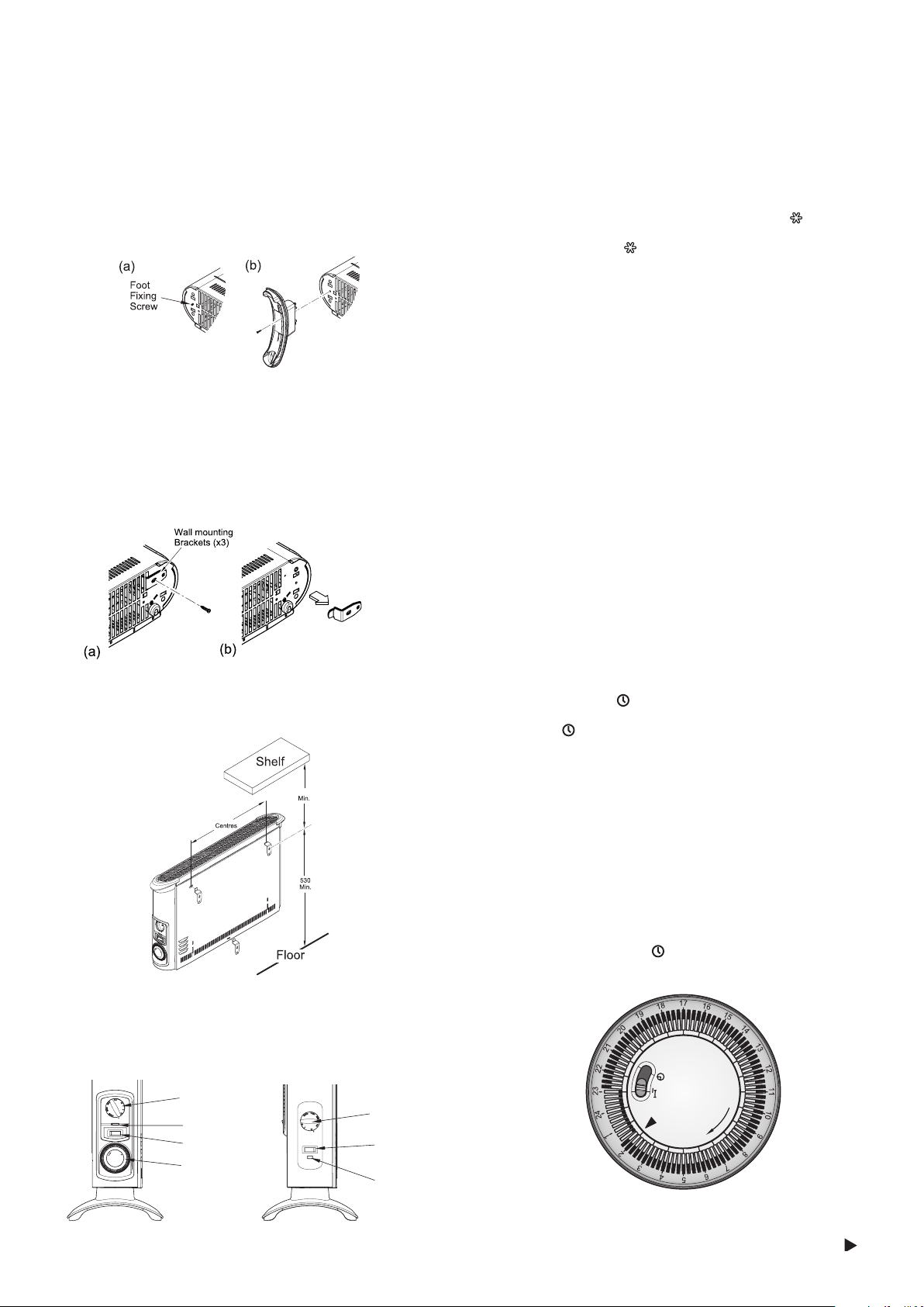
Controls
Model 403TSTi
Model 403TSF
Heat selector
switch
Thermostat
knob
Neon
Mechanical
Timer
Control
switch
Thermostat
knob
Neon
Thermostat (all models)
The thermostat controls the heat output according to the room temperature.
This ensures that the heater will not produce heat unnecessarily when the
room is warm.
To set the temperature you require, gradually turn the thermostat knob
clockwise until the desired temperature is reached. Allow some time
between increments for the room temperature to stabilise.
Alternatively to heat a cold room quickly, turn the thermostat knob to the
Max position. When the room has reached the desired temperature, turn
the thermostat knob anti-clockwise until the thermostat clicks off. The heater
will then automatically maintain this room temperature.
The thermostat also has a frost protection setting marked ‘ ’. This setting is
useful in areas such as garages to prevent frost damage. If the thermostat is
set to its minimum setting ‘ ’, the heater will cycle ON and OFF to maintain
a temperature of approximately 5°C to help protect against frosty conditions.
Switches (selected models)
Some models are supplied with selector switches . There are two switch
types, one is an on/off switch and the other is a heat selection switch.
Depending on model either one or both switch may be included. The switch
operation is as follows.
On/ Off: O - Off
I - On
Heat selection I - Low heat
II - High heat
403TS Operation
This model contains an On/Off switch and a heat selection switch and
operates as follows.
When O/I switch is in position O the product is off regardless of any other
setting. When O/I switch is in position I and the I/II switch is in the I position
there is a low heat output from the product. When O/I switch is in position
I and the I/II switch is in the II position there is a high heat output from the
product. The indicator neon is always on when the product is connected
to the mains supply.
403TSTi Operation
This model contains a heat selection switch and an electro-mechanical
timer and operates as follows.
When the timer is switched to I and the I/II switch is in position I there is
a low heat output from the product. When the timer is switched to I and
the I/II switch is in position II there is a high heat output from the product.
When the timer is in the ‘ ’ position and the I/II switch is in position I there
is a low heat output from the product when the timer is set on. When the
timer is in the ‘ ’ position and the I/II switch is in position II there is a high
heat output from the product when the timer is set on. The indicator neon
is always on when the product is connected to the mains supply.
Mechanical Timer (403TSTi)
Note: The timer clock will only operate when the product is connected to
the mains supply
Operation modes
There are two operating modes on the timer, Manual operation and Auto
operation. The operation mode is set using the slide switch on the timer
- see g6.
Manual operation (Position - I)
This setting allows power to the product uninterrupted by the timer,
however other product controls will continue to function as normal.
Auto operation (Position - )
This setting allows the heater to be controlled by the timer. The product
will be switched on and off depending on the pre-set timer program.
Setting the time of day
To set the time of day, rotate the timer dial clockwise (indicated by the
arrow) until the correct time of day is opposite the reference mark -
see Fig.6. The 24-hour clock is used ; e.g. 4 pm is ‘16’ (16:00hrs).
Fig.6
Fig. 4
Fig. 5
Fig. 3
Fig. 2
Loading ...
Loading ...