Loading ...
Loading ...
Loading ...
Replacing the Burner Door Assembly
Fire or Explosion Hazard
° Tightenboth manifolddoor screws securely.
• Remove any flbergtassbetween gasket and
combustion chamber.
• Replace viewport if glass is missing or damaged,
• Replace two piece wire connector if missing or
removed_
• Replace door gasket if damaged.
• Failure to follow these instructions can result in
death, explosion, or fire,
!_ Read instructionmanuai before
installing,using or servicing
water heater
1. Check the door gasket for damage or imbedded debris
prior to installation.
2. Inspect the viewportfor damage and replace as required.
3. Insert the burner doorassembly intothe combustion
chamber and slide it completelyforward. Note: When
insertingthe burner door assembly,tipthe burner end up
slightlytoensure it engages with the burner bracket.
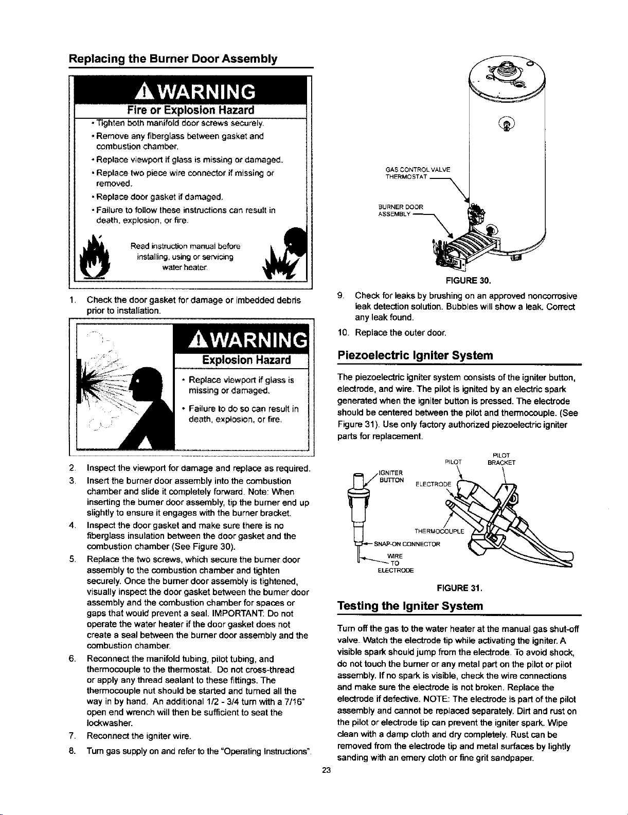
4. Inspect the doorgasket and make sure there isno
fiberglass insulationbetween the doorgasket and the
combustion chamber (See Figure 30).
5. Replace the two screws, whichsecure the burner door
assembly tothe combustion chamber and tighten
securely.Once the burner door assembly istightened,
visually inspectthe doorgasket between the burnerdoor
assembly and the combustionchamber for spaces or
gaps that would prevent a seal. IMPORTAN'E Do not
operate the water heater ifthe door gasket does not
create a seal between the burner door assembly and the
combustion chamber.
6.
7.
8.
Reconnect the manifold tubing,pilot tubing, and
therrnocoupleto the thermostat. Do not cress-thread
or apply any thread sealant to these fittings. The
thermoceuple nut should be started and turned all the
way in by hand. An additional 1/2 - 3/4 turn with a 7/16"
open end wrench will then be sufficient to seat the
Iockwasher.
Reconnect the igniter wire.
"rumgas supplyonand referto the "Operating Instructions".
GASCONTROLVALVE
BURNERDOOR
ASSEMBLY'_
23
FIGURE 30.
9. Check for leaks bybrushingon an approved noncorrosive
leak detectionsolution.Bubbleswill show a leak. Correct
any leak found.
10. Replace the outer door.
Piezoelectric Igniter System
The piezoelectric igniter system consists of the igniter button,
electrede, and wire. The pilct is ignited by an electdcspark
generated when the igniter button is pressed. The electrode
should be centered between the pilot and thermoceuple. (See
Figure 31). Use only factory authorized piezoelectric igniter
parts for replacement.
PILOT
PILOT BRACKET
_SNAP_N coNTHERoOCOU PLE Q
ELECTRODE
FIGURE 31.
Testing the Igniter System
Turn off the gas to the water heater at the manual gas shut-off
valve. Watch the electrodetip while activatingthe ignit_r.A
visible sparkshouldjump fromthe electrode. Toavoid shock,
do not touchthe burner or any metal part onthe pilotor pilot
assembly. Ifno spark is visible, checkthe wire connections
and make sure the electrode is not broken. Replace the
electrode ifdefective. NOTE: The electrode is part ofthe pilot
assembly and cannot be replaced separately. Dirt and rust on
the pilotor electrodetip can prevent the igniterspark. Wipe
clean with a damp cloth and dry cempletely. Rust can be
removed from the electrode tipand metal surfaces by lightly
sanding with anemery clothor fine gdt sandpaper.
Loading ...
Loading ...
Loading ...