Use & Care Guide for Hood
INSTALLATION INSTRUCTIONS
Prepare Location
NOTE: It is recommended that the vent system be installed before hood is installed.
Before making cutouts, make sure there is proper clearance within the ceiling or wall for exhaust vent.
1. Disconnect power.
WARNING Electrical Shock Hazard Disconnect power before servicing.
Replace all parts and panels before operating.
Failure to do so can result in death or electrical shock.
2. Depending on your model, determine which venting method to use: roof, wall, or non-vented (recirculating).
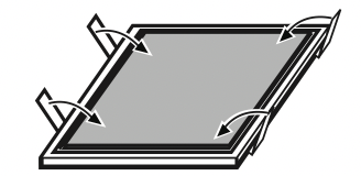
3. Select a flat surface for assembling the range hood. Place covering over that surface.
4. Lift the range hood and set it upside down onto covered surface.
Determine Wiring Hole Location
Cut only one 1¹⁄4 " (3.2 cm) diameter wiring access hole.
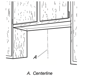
1. Determine and clearly mark a vertical centerline on the wall and cabinet in the area the vent opening will be made.
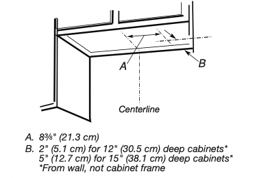
To wire through top:
1. Mark a line distance “A” from the right of the centerline on the underside of the cabinet. For 12" (30.5 cm) deep cabinets, mark the point on this line that is 2" (5.1 cm) from the back wall. For 15" (38.1 cm) deep cabinets, mark the point on this line that is 5" (12.7 cm) from the back wall. Drill a 1¼" (3.2 cm) diameter hole through the cabinet at this point.
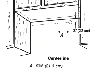
To wire through wall:
1. Mark a line distance “A” from the right of the centerline on the underside of the wall. Mark the point on this line that is 7 ⁄8 " (2.2 cm) from the underside of the cabinet. Drill a 1¹⁄4 " (3.2 cm) diameter hole through the rear wall at this point.
Style 1 - Cut Openings for 3¼" x 10" (8.3 cm x 25.4 cm) Rectangular Vent System
Roof Venting
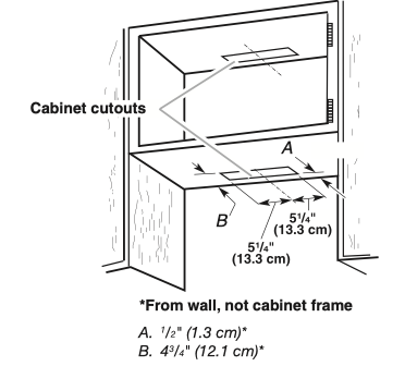
To make a 4¹⁄4 " x 10½" (10.8 cm x 26.7 cm) rectangular cutout on the underside of cabinet top and bottom:
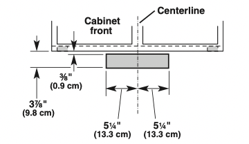
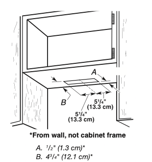
1. Mark lines ¹⁄2 " (1.3 cm) and 4³⁄4 " (12.1 cm) from the back wall on the centerline of the underside of cabinet.
2. Mark lines 5¼" (13.3 cm) to the right and left of the centerline on the underside of cabinet.
3. Use saber or keyhole saw to cut a rectangular opening for vent.
4. Repeat steps 1-3 for the underside of the top of the cabinet.
Wall Venting
To make a 3½" x 10½" (8.9 cm x 26.7 cm) rectangle in the wall:
1. Make 2 lines by measuring ³⁄8 " (0.9 cm) and 37 ⁄8 " (9.8 cm) down from underside of cabinet and mark on the centerline on the back wall.
2. Mark lines 5¼" (13.3 cm) to the right and left of the centerline on the wall.
3. Use saber or keyhole saw to cut a rectangular opening in the wall for the vent.
Style 2 - Cut Openings for 3¼" x 10" (8.3 x 25.4 cm) Rectangular Vent to Round Vent Transition
Roof Venting
To make a 4¹⁄4 " x 10½" (10.8 cm x 26.7 cm) rectangular cutout on the underside of cabinet bottom:
1. Mark lines ¹⁄2 " (1.3 cm) and 4³⁄4 " (12.1 cm) from the back wall on the centerline of the underside of cabinet.
2. Mark lines 5¼" (13.3 cm) to the right and left of the centerline on the underside of cabinet.
3. Use saber or keyhole saw to cut a rectangular opening for vent.
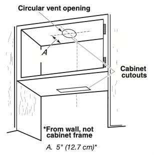
To make a circular vent opening on the underside of the cabinet top:
1. Mark a centerline on the underside of the top of cabinet.
2. Mark a line 5" (12.7 cm) from the back wall on the underside of the top of cabinet.
3. Use a compass or a circle template to draw a circle with a diameter that is ¼" (0.64 cm) larger than the vent.
4. Use saber or keyhole saw to cut the circular vent opening.
Style 3 - Cut Openings for 7" (17.8 cm) Round Vent
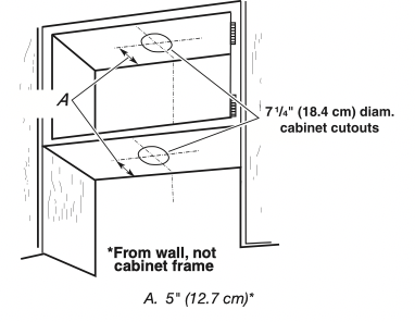
To make a circular vent openings on the underside of the cabinet top and bottom:
1. Mark a centerline on the underside of the top of cabinet.
2. Mark a line 5" (12.7 cm) from the back wall on the underside of the top and bottom of cabinet.
3. Use a compass or a circle template to draw a circle with a diameter that is ¼" (0.64 cm) larger than the vent.
4. Use saber or keyhole saw to cut the circular vent opening.
Install Vent System
1. Install vent through the vent opening in upper cabinet or wall. Complete venting system according to the selected venting method. See the “Venting Requirements” section.
2. Use caulking to seal exterior wall or roof opening around the cap.
Prepare Range Hood
Only for venting through the top/wall options:
1. Remove vent knockouts, depending on your installation requirements.
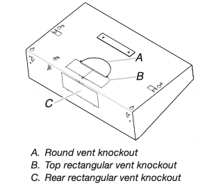
Round vent system installations - Remove top rectangular and round vent knockouts.
Rectangular vent system installations - For roof installations, remove the top rectangular vent knockout. For wall installations, remove the rear rectangular vent knockout.
Non-vent (recirculating) installations - Do not remove any knockouts.
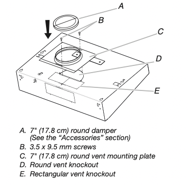
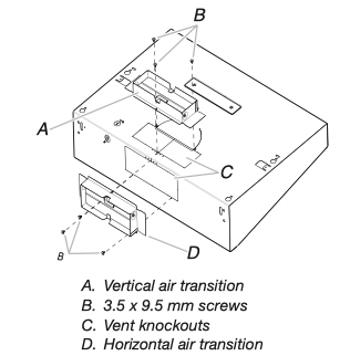
2. Install 7" (17.8 cm) round vent mounting plate or 3¹⁄4 " x 10" (8.3 cm x 25.4 cm) vent damper, depending on your vent system installation. Attach to range hood with 3.5 x 9.5 mm screws provided and remove the tape from the damper flap.
NOTE: An optional 7" (17.8 cm) round damper is also available as an accessory. For information on ordering, see the “Accessories” section.
NOTE: The round vent damper may only be installed on the top of the product.
Only for recirculating options
For this venting method, it is neccesary to purchase a Charcoal Filter Kit. See the “Accessories” section for ordering.
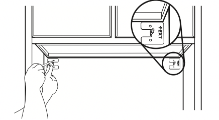
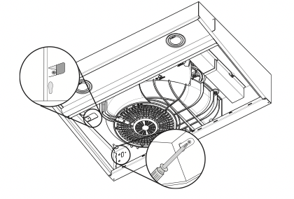
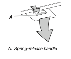
1. Remove each filter by pulling the spring-release handle and then pulling down the filter.
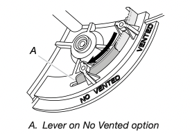
2. Remove the venting method screw from the Vented option with a TORX ® T10 screwdriver and set aside.
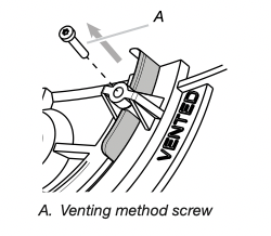
3. Slide the venting lever down as shown in the following image.
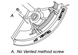
4. Replace the venting method screw on the No Vented (recirculating) option.
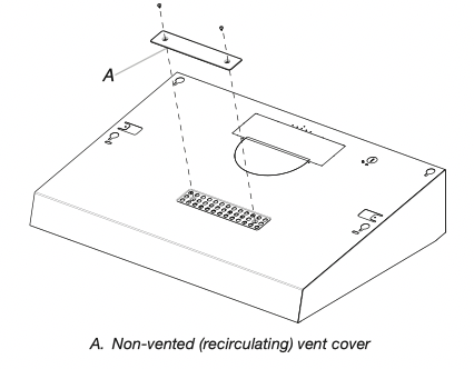
5. Remove the non-vented (recirculating) vent cover.
6. Bend spring clips away from metal grease filter.
7. Place charcoal filter into top side of metal filter.
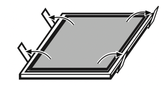
8. Bend spring clips back into place to secure the charcoal filter to the metal filter.
9. Replace metal grease filter.
Install Range Hood
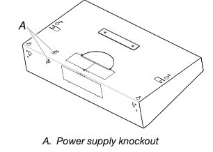
1. Remove the power supply knockout from the top or rear of the vent hood (depending on the incoming location of your home power supply cable) and install a UL Listed or CSA Approved ¹⁄2 " strain relief.
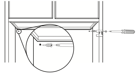
2. Align the exterior edge of the mounting brackets with the exterior edges of the upper cabinet.
IMPORTANT: The brackets should touch the upper cabinet. With a pencil, mark the upper holes on the brackets.
3. Using a #2 Phillips screwdriver, install the drywall anchors. Using #8-18 x 1" (4.2 x 25 mm) flat-head #2 Phillips screws, install the mounting brackets using the upper holes.
NOTE: For installation to a surface other than drywall, it is recommended that a qualified contractor determine the anchoring method.
4. Lift the range hood into place and insert the mounting bracket tabs through the slots in the back of the range hood.
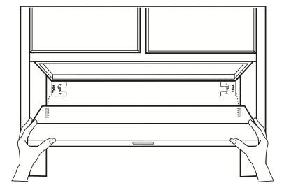
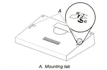
5. From the inside of the range hood, start a #8-18 x5 ⁄8 " (4.2 x 16 mm) truss-head screw into the mounting tab (A) on each side of the range hood as shown in the following inset. Insert the screws approximately 2 turns into the mounting tab holes. Bend each mounting tab upward approximately 45°.
6. Lift the range hood into place, positioning the rear slots over the mounting brackets.
7. Using a Phillips screwdriver, push on the screws that are started into the top mounting tabs and bend the tabs against the cabinet side walls. Attach the screws to the cabinet side walls.
8. For direct wire installations, run the home power supply cable according to the National Electric Code or CSA standards and local codes and ordinances. There must be enough wiring from the fused disconnect (or circuit breaker) box to make the connection in the range hood electrical terminal box.
9. Tighten the strain relief screws.
NOTE: Do not reconnect power until the installation is complete.
OPTIONAL: If you prefer, bend the rear tabs against the rear of the range hood and attach to the wall using #8-18 x5 /8" (4.2 x 16 mm) truss-head screws.
Connect Vent System
Connect the ventwork to the range hood. Seal joints with vent clamps or duct tape to make secure and airtight. Check that the backdraft dampers work properly.
Power Supply Cable Installation
1. For direct wire installations, run the home power supply cable according to the National Electric Code or CSA standards and local codes and ordinances. There must be enough wiring from the fused disconnect (or circuit breaker) box to make the connection in the hood electrical terminal box.
For optional power supply cord kit (see the “Accessories” section), follow the instructions in the “Make Electrical Connections” section.
NOTES:
■ Use only with range hood cord connection kits that have been investigated and found acceptable for use with this model range hood.
■ Do not reconnect power until the installation is complete.
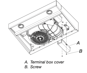
2. Remove the screw from the terminal box cover. Remove terminal box cover and set aside.
Make Electrical Connection
Option 1 - Direct Wire Installations
WARNING
Electrical Shock Hazard Disconnect power before servicing.
Replace all parts and panels before operating.
Failure to do so can result in death or electrical shock.
1. Disconnect power.
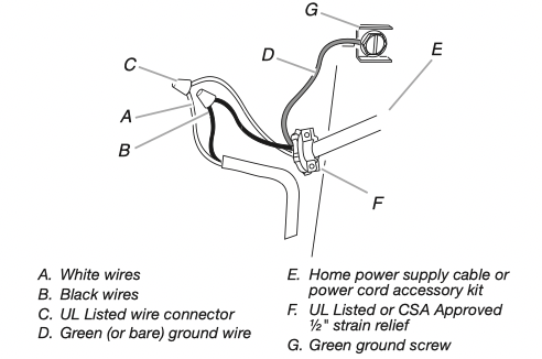
2. Use UL Listed wire connectors and connect white wires (A) together.
3. Use UL Listed wire connectors and connect black wires (B) together.
WARNING
Fire Hazard Electrically ground the blower.
Use copper wire.
Connect ground wire to green ground screw in terminal box.
Failure to do so can result in death, fire, or electrical shock.
4. Connect green (or bare) ground wire from power supply to green ground screw in terminal box and securely tighten.
5. Install terminal box cover.
6. Reconnect power.
Option 2 - Power Cord Kit Installations
For optional power cord kit installations, follow the instructions supplied with the power cord kit. See the “Accessories” section for information on ordering.
NOTE: Use only with range hood cord connection kits that have been investigated and found acceptable for use with this model range hood.
Complete Installation
1. Replace grease filter if removed. See the “Range Hood Care” section.
2. Check the operation of the range hood fan and light. See the “Range Hood Use” section.
If range hood does not operate, check to see whether a circuit breaker has tripped or a household fuse has blown. Disconnect power and check wiring connections.
NOTE: To get the most efficient use from your new range hood, read the “Range Hood Use” section.
RANGE HOOD USE
The range hood is designed to remove smoke, cooking vapors, and odors from the cooktop area. For best results, start the hood before cooking and allow it to operate several minutes after the cooking is complete to clear all smoke and odors from the kitchen.
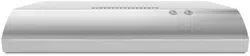
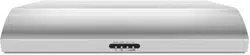
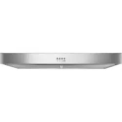
The hood controls are located on the front panel of the range hood.
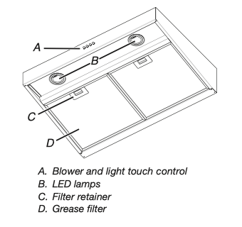
Range Hood Controls
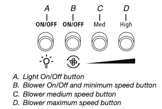
Operating the light
The Light On/Off button controls both lights. Press once for ON and again for OFF.
Operating the blower
The blower buttons turn the blower on/off and control the blower speed and sound level for quiet operation. The speed can be changed anytime during fan operation by pressing the desired blower speed button.
Press the blower On/Off button a second time to turn the blower off.
RANGE HOOD CARE
Cleaning
IMPORTANT: Clean the hood and grease filters frequently according to the following instructions. Replace grease filter before operating hood.
Exterior Surfaces
IMPORTANT: Do not use soap-filled scouring pads, abrasive cleaners, cooktop polishing creme, steel wool, gritty washcloths or paper towels.
To avoid damage to the stainless steel, do not use cleaners that contain chlorine.
Cleaning Method:
■ Rub in direction of grain to avoid scratching or damaging the surface.
■ For stainless steel models, Stainless Steel Cleaner and Polish Part Number 31462A (not included): See the “Assistance or Service” section to order.
■ Liquid detergent or all-purpose cleaner: Rinse with clean water and dry with soft, lint-free cloth.
■ Glass cleaner to remove fingerprints.
Metal Grease Filter
For vented installations:
1. Remove each filter by pulling the spring-release handle and then pulling down the filter.
2. Wash metal filter as needed in dishwasher or hot detergent solution.
3. Reinstall the filter by making sure the spring-release handles are toward the front. Insert aluminum filter into upper track.
4. Push in spring-release handle.
5. Push up on metal filter and release handle to latch into place.
6. Repeat steps 1-5 for the other filter.
For non-vented (recirculating) installations:
The charcoal filter is not washable. It should last up to 6 months with normal use. Replace with Charcoal Filter Kit. See the “Assistance or Service” section for information on ordering.
Replacing an LED Lamp
The LED lights are replaceable by a service technician only. See the “Warranty” section for service contact information.
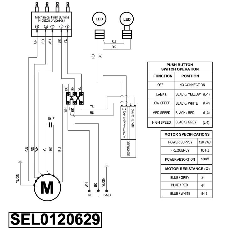
WIRING DIAGRAM