Loading ...
Loading ...
Loading ...
16 49-80777 Rev. 3
Installation Instructions
INSTALLATION INSTRUCTIONS
2
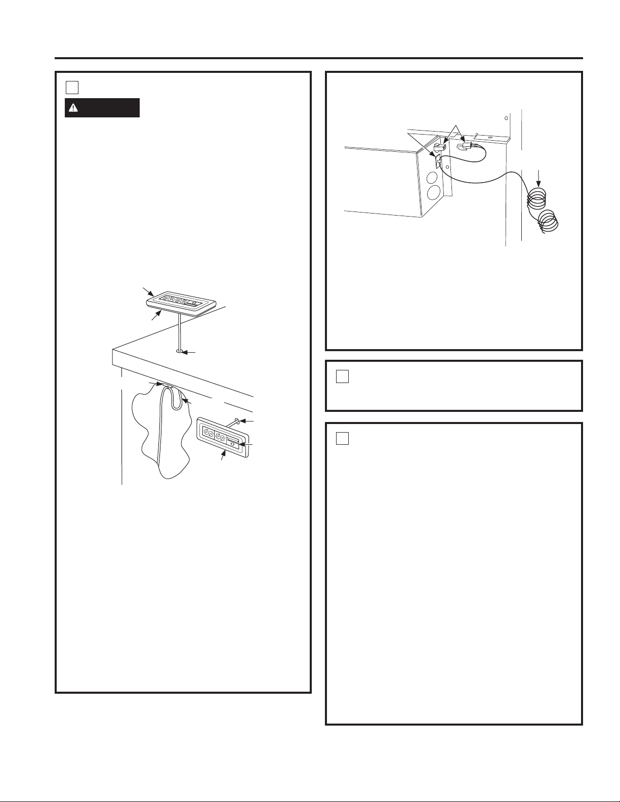
INSTALL REMOTE SWITCH
WARNING
BURN HAZARD
The remote switch must be located so that it can be
operated without reaching over the cooktop. Failure
to do so may result in ignition of clothing which
could cause serious injury or death.
Determine the location for the remote switch.
• Disconnect the remote switch from the harness.
• The remote switch should be located so that
the vertical distance from the floor to the remote
switch is less than 48" and more than 15".
• The remote switch harness is 68" long and should
be installed so that it is not pinched and is away
from moving parts.
• Use the remote switch to determine the exact
center of the hole, confirm there is clearance
behind the hole for the connector and wire to pass
into, and drill a 1/2" diameter hole.
• If the remote switch is not installed on the
countertop, ensure that it is installed in a location
that meets local codes and is easily accessible.
Connect Remote Switch to Remote Harness
• Thread the remote harness through the 1/2"-dia.
hole and attach the harness connector to the
remote connector.
• Remove the paper backing on the remote switch
foam piece and mount the remote switch on the
countertop such that the switch connectors stay
located in the 1/2"-dia. hole.
• Stick adhesive wire clamp near the 1/2"-dia. hole
and attach the loose wire with a wire tie.
Connect Wire Lead to Control Box
• Connect the mating wire ends.
• Place the adhesive wire clamps (provided) near
the mating connector.
• Keep approximately 3"-long wire and attach the
wire to the clamp with a wire tie. This will act as a
strain relief.
1/2"-Dia. Hole
1/2"-Dia.
Hole
Foam Piece With Adhesive
Mounting Surface
Foam Piece With Adhesive
Mounting Surface
Remote Switch
Remote
Switch
Strain Relief
(Adhesive wire clamp
with tie)
Remote
Harness
Control
Box
Remote
Harness
Mating Connectors
Strain Relief
(Adhesive wire
clamp with tie)
3
CONNECT POWER
Plug power cord into properly grounded receptacle.
4
INSTALL FILTERS, CHECK
OPERATION
• Press the ON/OFF pad on the control
to raise the vent.
• Slip fingers into the vent holes. Lift the vent
straight up and pull forward.
• Slide filter into the retainers and close the vent.
• Press the Fan Speed HIGHER pad to start the
blower. Adjust the blower by pressing HIGHER or
LOWER.
• To lower the vent, press the ON/OFF pad.
NOTE: It is not necessary to turn the fan OFF
before lowering the vent. The fan will automatically
turn off when the vent is lowered. When the fan
is not turned off before lowering the vent, it will
automatically come on at the previously set speed
when the vent is fully raised.
IMPORTANT: The vent can be activated by
pressing the pads on the switch. Do not use
excessive force or sharp objects to activate the
switch. Damage could occur and void the warranty.
Loading ...
Loading ...
Loading ...