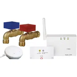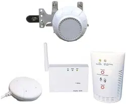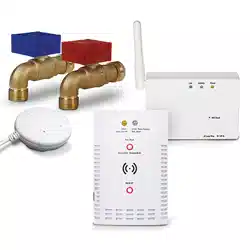
Smart Module
Mounting Template
Control Unit
Mounting template
Drywall screws
SMART Laundry Shut Off System
DIY Quickstart Guide
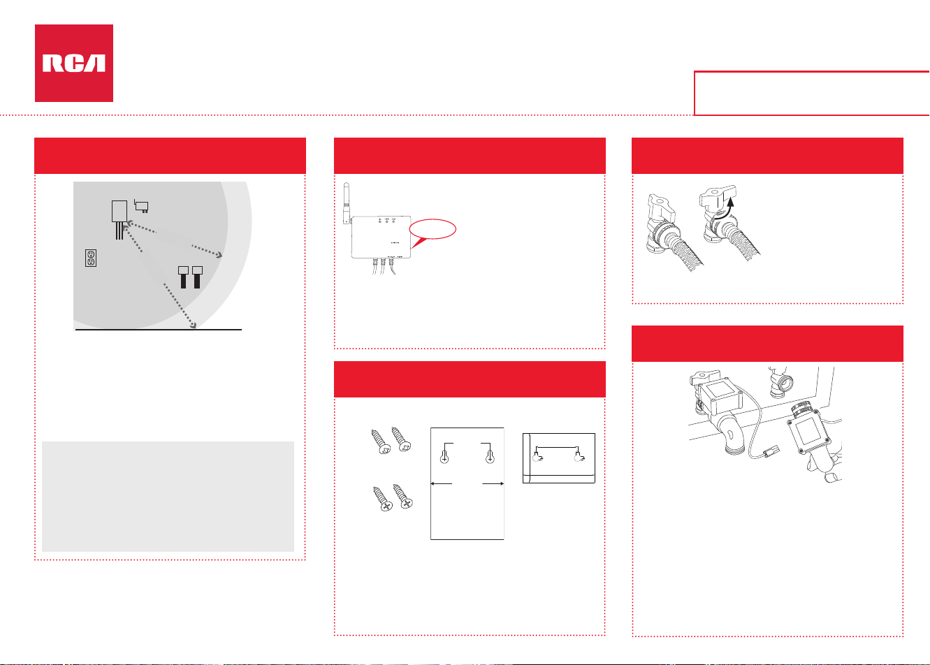
The control unit needs to be close enough to the
shut-off valves and oor for the sensor wire (6ft)
and control lead wires (5ft) to reach.
The smart module should be between the control
unit and the shut-off valves. It also needs to be
close to a power outlet.
There are three mounting options:
- Double-sided tape (included, not for masonry applica-
tions)
- Drywall screws with anchors (included), using the mount-
ing template (included)
- Masonry screws (included), using the mounting template
(included)
Off
Turn each valve
90-degrees counter-
clockwise to turn it off.
Place a bucket and
towels under the shut-
off valves before you
remove the hoses.
Remove the plastic protectors from both ends of
each automatic shut-off valve. Make sure the rubber
o-rings are seated properly (at) inside each hose
tting.
Match the red automatic shut-off valve (HOT) to the
red valve and the blue (COLD) to the blue valve.
Screw each hose tting onto the automatic shut-off
valves. Hand-tighten the collar of the tting onto the
washer shut-off valve (use a channel lock or pliers
for the last quarter-turn).
Make sure each laundry hose
still has its o-ring inside the hose
tting. If it doesn’t, use one of
the extra o-rings provided in this
package.
Match each hose to the shut-off
valve it was on before. Then screw
each hose on tight by hand (use a
channel lock or pliers for the last
quarter-turn).
Continues on back...
Masonry screws
45mm(1.77")
72mm(2.83")
MOUNTING TEMPLATE
USE FOR FLAT
WALL MOUNT ONLY
FOR THE CONTROL UNIT
Less than 5ft
Less than 6ft
Control
unit
Floor
Shut-off
valves
Power
outlet
Smart module
IMPORTANT: The smart module needs a strong signal
from your WiFi router to work properly. Test the strength
of your WiFi network’s signal where you plan to mount
the smart module—make sure your phone is on the WiFi
network you want to use, then look at the WiFi signal
meter on your phone’s screen. Make sure you’re getting
at least 50% signal strength where you plan to install. If
not, try moving your WiFi router closer (or installing a
WiFi signal booster close to the installation).
The back and side of the
smart module list its MAC
address. You’ll need this
to add the module to
the App and your WiFi
network later on, so you
should nd it and write
it down now, before you
mount the smart module
to the wall.
Smart module,
back and side
Smart Module
MAC Address:________________________
MOUNTING TEMPLATE
USE FOR FLAT
WALL MOUNT ONLY
( 2 ")
( 3.45")
( 2.36")
50.8mm
87.5mm
60.0mm
Control
Box
Shut-Off Valves
Smart
Module
Control
Box
Shut-Off Valves
Smart
Module
Control
Box
Shut-Off Valves
Smart
Module
Control
Box
Shut-Off Valves
Smart
Module
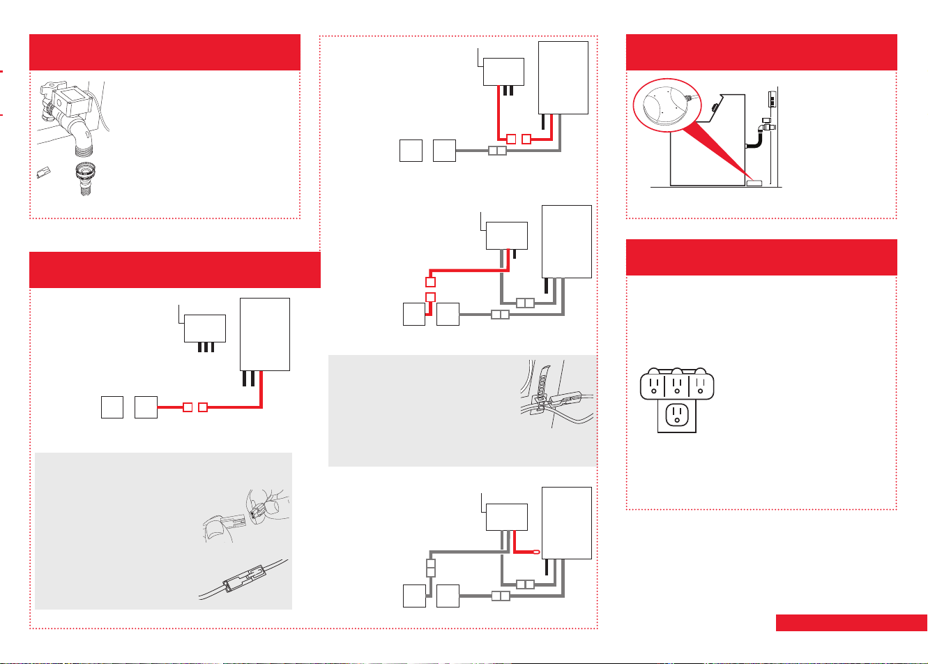
DC In
A. Connect the lead from
one shut-off valve to a
control box lead.
B. Connect the second
control box lead to the
rst lead from the smart
module.
C. Connect the middle
lead from the smart
module to the other
shut-off valve.
D. Connect the third cord
from the smart module
to the DC In jack on the
control box.
How to connect leads
1. Line up the round and
square plugs on each
control box lead to the
corresponding round and
square holes on the lead
from the auto shut-off boxes.
2. Snap both pairs of leads
into place.
Use the included wire ties to gather
the wires and stick them to the wall
so that they’re out of the way.
Clean the wall rst. Then stick the
back of the wire tie to the wall. Use
the other wire tie closer to the control box to gather
the wires there as well.
Agua detectada
Make sure the
sensor is sitting at
on the oor directly
beneath the shutoff
valves. (Do not
place it inside the
washer oor tray if
you have one.)
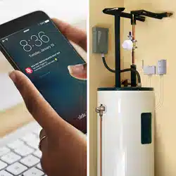
Plug the smart module’s power adapter into the
jack on the side of the smart module.
Plug the other end of the power adapter into an
available power outlet.
If both power outlets are in
use (by the washer and dryer,
for example), use the included
3-outlet power wall tap to provide
additional outlets.
When the smart module and
control unit rst power on, the
yellow indicator light on the front
panel of the control unit ashes—the auto shut off
valve system is arming and opening valves. When
the green indicator light comes on, the system is
ready to use.
3-outlet power
wall tap
For detailed instructions, see the
Installation Guide.
Find the best place to mount the
control unit and smart module.
Write down the smart module’s
MAC address.
Mount the control unit and smart module
to your wall.
Turn off your washer’s shut-off valves and
remove the washer hoses from the valves.
Install the automatic shut-off valves on the
washer shut-off valves.
1 2 4
3
5
Screw the hoses onto each automatic
shut-off valve.
6
Connect the control box, smart module,
and shut-off valves.
7
Place the leak sensor on the oor beneath
the washer shutoff valves.
8
Plug in the smart module.
9
Rating LABEL
2018/03/27
MODI-IOT
67630551460G
A
0.1
YangZhiQiang
条码读码为: 70F8E7262881
此号码为16进制,每张标签之间需跳一码,
即第一张号码为70F8E7262881,则第二
张号码为70F8E7262883,.....此次流水号为
此次流水号为
GMA252V13F0001~GMA252V13F0100
70F8E7262881~70F8E7262947,共100张.
MAC NUMBER
MAC
SN: GMA252V13F0001
: 70F8E7262881
SMART MODULE
MADE IN CHINA
CAN ICES-3(B)/NMB-3(B)
FCC ID: VIXMOD1
IC: 21578-MOD1
MODEL: MOD1
INPUT: 12V 1A
30.0mm
36.0mm
条码读码为:
GMA252V13F0001
Serial number
F:
GMA25:Model code(MOD1-IOT)Assigned by AEC
V: Manufactured year(V=2018,skip I,O,S,Z)
13: Manufactured week
2
TO: 采购
2018.03.27
Smart Module
Mounting Template
Control Unit
Mounting template
Drywall screws
SMART Laundry Shut Off System
DIY Quickstart Guide
The control unit needs to be close enough to the
shut-off valves and oor for the sensor wire (6ft)
and control lead wires (5ft) to reach.
The smart module should be between the control
unit and the shut-off valves. It also needs to be
close to a power outlet.
There are three mounting options:
- Double-sided tape (included, not for masonry applica-
tions)
- Drywall screws with anchors (included), using the mount-
ing template (included)
- Masonry screws (included), using the mounting template
(included)
Off
Turn each valve
90-degrees counter-
clockwise to turn it off.
Place a bucket and
towels under the shut-
off valves before you
remove the hoses.
Remove the plastic protectors from both ends of
each automatic shut-off valve. Make sure the rubber
o-rings are seated properly (at) inside each hose
tting.
Match the red automatic shut-off valve (HOT) to the
red valve and the blue (COLD) to the blue valve.
Screw each hose tting onto the automatic shut-off
valves. Hand-tighten the collar of the tting onto the
washer shut-off valve (use a channel lock or pliers
for the last quarter-turn).
Make sure each laundry hose
still has its o-ring inside the hose
tting. If it doesn’t, use one of
the extra o-rings provided in this
package.
Match each hose to the shut-off
valve it was on before. Then screw
each hose on tight by hand (use a
channel lock or pliers for the last
quarter-turn).
Continues on back...
Masonry screws
45mm(1.77")
72mm(2.83")
MOUNTING TEMPLATE
USE FOR FLAT
WALL MOUNT ONLY
FOR THE CONTROL UNIT
Less than 5ft
Less than 6ft
Control
unit
Floor
Shut-off
valves
Power
outlet
Smart module
IMPORTANT: The smart module needs a strong signal
from your WiFi router to work properly. Test the strength
of your WiFi network’s signal where you plan to mount
the smart module—make sure your phone is on the WiFi
network you want to use, then look at the WiFi signal
meter on your phone’s screen. Make sure you’re getting
at least 50% signal strength where you plan to install. If
not, try moving your WiFi router closer (or installing a
WiFi signal booster close to the installation).
The back and side of the
smart module list its MAC
address. You’ll need this
to add the module to
the App and your WiFi
network later on, so you
should nd it and write
it down now, before you
mount the smart module
to the wall.
Smart module,
back and side
Smart Module
MAC Address:________________________
MOUNTING TEMPLATE
USE FOR FLAT
WALL MOUNT ONLY
( 2 ")
( 3.45")
( 2.36")
50.8mm
87.5mm
60.0mm
Control
Box
Shut-Off Valves
Smart
Module
Control
Box
Shut-Off Valves
Smart
Module
Control
Box
Shut-Off Valves
Smart
Module
Control
Box
Shut-Off Valves
Smart
Module
DC In
A. Connect the lead from
one shut-off valve to a
control box lead.
B. Connect the second
control box lead to the
rst lead from the smart
module.
C. Connect the middle
lead from the smart
module to the other
shut-off valve.
D. Connect the third cord
from the smart module
to the DC In jack on the
control box.
How to connect leads
1. Line up the round and
square plugs on each
control box lead to the
corresponding round and
square holes on the lead
from the auto shut-off boxes.
2. Snap both pairs of leads
into place.
Use the included wire ties to gather
the wires and stick them to the wall
so that they’re out of the way.
Clean the wall rst. Then stick the
back of the wire tie to the wall. Use
the other wire tie closer to the control box to gather
the wires there as well.
Agua detectada
Make sure the
sensor is sitting at
on the oor directly
beneath the shutoff
valves. (Do not
place it inside the
washer oor tray if
you have one.)
Plug the smart module’s power adapter into the
jack on the side of the smart module.
Plug the other end of the power adapter into an
available power outlet.
If both power outlets are in
use (by the washer and dryer,
for example), use the included
3-outlet power wall tap to provide
additional outlets.
When the smart module and
control unit rst power on, the
yellow indicator light on the front
panel of the control unit ashes—the auto shut off
valve system is arming and opening valves. When
the green indicator light comes on, the system is
ready to use.
3-outlet power
wall tap
For detailed instructions, see the
Installation Guide.
Find the best place to mount the
control unit and smart module.
Write down the smart module’s
MAC address.
Mount the control unit and smart module
to your wall.
Turn off your washer’s shut-off valves and
remove the washer hoses from the valves.
Install the automatic shut-off valves on the
washer shut-off valves.
1 2 4
3
5
Screw the hoses onto each automatic
shut-off valve.
6
Connect the control box, smart module,
and shut-off valves.
7
Place the leak sensor on the oor beneath
the washer shutoff valves.
8
Plug in the smart module.
9
Rating LABEL
2018/03/27
MODI-IOT
67630551460G
A
0.1
YangZhiQiang
条码读码为: 70F8E7262881
此号码为16进制,每张标签之间需跳一码,
即第一张号码为70F8E7262881,则第二
张号码为70F8E7262883,.....此次流水号为
此次流水号为
GMA252V13F0001~GMA252V13F0100
70F8E7262881~70F8E7262947,共100张.
MAC NUMBER
MAC
SN: GMA252V13F0001
: 70F8E7262881
SMART MODULE
MADE IN CHINA
CAN ICES-3(B)/NMB-3(B)
FCC ID: VIXMOD1
IC: 21578-MOD1
MODEL: MOD1
INPUT: 12V 1A
30.0mm
36.0mm
条码读码为:
GMA252V13F0001
Serial number
F:
GMA25:Model code(MOD1-IOT)Assigned by AEC
V: Manufactured year(V=2018,skip I,O,S,Z)
13: Manufactured week
2
TO: 采购
2018.03.27
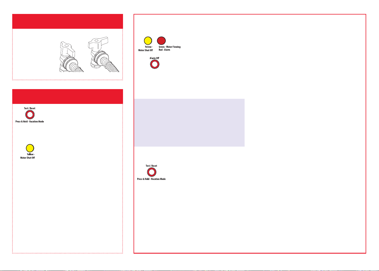
Using the auto shut-off
When the alarm goes off...
If the sensor senses water,
the alarm sounds and the
valves close. The yellow
and red indicators on the
control box start ashing.
You will also receive a
notication on your phone
saying “Device has been
triggered. Automatic shut-off
activated.”
Once you’ve xed the leak and dried off the sensor...
Press and release the Test/Reset
button on the control unit. The
yellow light ashes while the
valves are reopening. The green
light comes on when they have
nished reopening.
Losing power
If you lose power, the control box automatically
closes the shut off valves (more slowly than during
a real alarm), then powers off. You will also get
a notication on your phone saying “Device
Disconnected.” When power returns, if the sensor
does not detect water, the control box will open the
valves again.
Turn the laundry
shut off valves 90
degrees clockwise to
turn the water supply
on for both hoses.
Make sure there are
no leaks. If there are
leaks, tighten the
hose ttings.
Press and release the Test/Reset
button on the control unit.
NOTE: Press the Alarm Off button
immediately after to mute the sound.
The system’s alarm goes off, the
automatic valves close, and the
yellow indicator on control unit
starts ashing.
You will also receive a notication from the RCA
Water Shut-Off App (“TEST” will appear on your
screen).
Once the valves are completely closed, the control
unit will automatically re-open them again in about
30 seconds.
The yellow light ashes while the valves are
reopening. The green light comes on when they
have nished reopening.
The test process takes about 25 seconds to
complete and return to normal (valves open and
green light) status.
If the green light doesn’t come back on, unplug
the controller and plug it back in. Then test the
system again.
RSWL1 QSG 01
Customizing the alarm
By default, the audible alarm keeps sounding until you turn it
off (or until the sensor no longer senses water). You can also
set the audible alarm to sound for 10 seconds only.
To change the audible alarm to 10 seconds only: Press and
hold the Alarm Off button for 2-3 seconds. The yellow LED
ashes to show that you’ve changed the audible alarm to 10
seconds only. To change back, press and hold the Alarm Off
button again.
A. Download and install the App on your phone.
Search for “RCA Water Shut-Off”
in the Apple App or Google Play
Stores. Look for the icon shown
here and install this App on your
phone.
IMPORTANT!!!
• Make sure your phone is on the WiFi network you
want the Smart Water Shut-Off system to use.
• If you have a dual-band router that uses different
networks for the two bands, make sure the WiFi
signal you use is 2.4GHz, not 5GHz!
• Make sure your Smart Module is ready for setup!
The Link and Activity indicators on the Smart
Module are on when the Smart Module is in Setup
mode. The Smart Module goes into Setup Mode
automatically when you rst power it up and
stays in Setup Mode for 6 minutes. If the Link and
Activity indicators on the Smart Module are not
on, unplug the Smart Module and plug it in again.
Shut-off valves
On
Off
To stop the audible alarm: On the control unit, press
the Alarm Off button. (The valves will still be closed.)
Vacation Mode
If you plan to be away from home for an extended
period, put the system in Vacation Mode to shut
the valves while you’re gone. Simply press and hold
the Test/Reset button for three seconds. The yellow
indicator light blinks while the valves are closing and
turns solid yellow with the valves are closed.
When you get back, press and release the Test/Reset
button again to open the valves. The yellow indicator
light blinks while the valves are opening; the green
indicator comes on when the valves are open.
App Notications Guide
If your phone
says...
This means...
“Device has been
triggered. Automatic
shut-off activated.”
Your sensor has detected
water and automatically
shut valves.
“TEST” Your system has gone
through a test and will re-
open valves when nished.
“Device connected” Your system has regained
power and re-opened
valves.
“Device
disconnected”
Your system has lost power
and automatically shut
valves.
“Device has re-
connected to WiFi”
Your smart module lost its
WiFi connection but is now
re-connected.
Set up the App with your system.
10
Turn on the water supply.
11
Test the system.
12
B. Launch the App
The rst time you open the App, you’ll be asked
if you want to allow the RCA Water Shut-Off App
to send you notications. Make sure you choose
Allow in this step so that the App can notify you
when needed!
Make sure your Smart Module is ready for setup!
If the Link and Activity indicators on the Smart
Module are not on, unplug the Smart Module and
plug it in again.
Make sure you’re on the WiFi network you want
to use!
If the Network Name doesn’t match the network you
want to use, quit the App, go to the network settings
for your phone, and connect to the network you
want to use. Then start the App again.
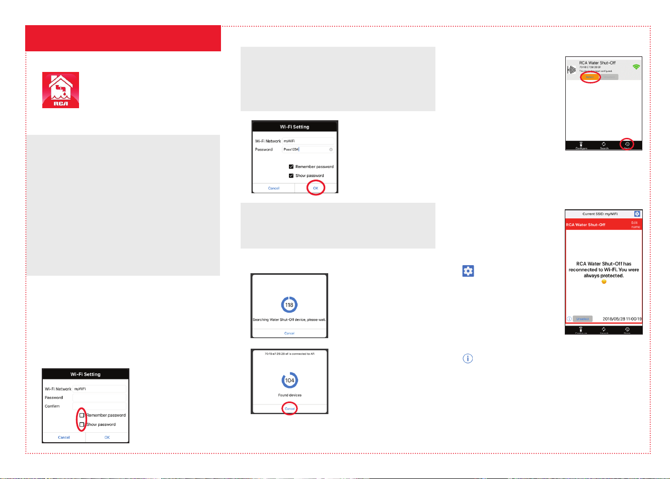
C. Connect the App to your WiFi network
Press the Remember
Password and Show
Password boxes so that
you only have to enter
your password once
(and you can see it
while you’re entering).
Enter the password for
your WiFi network. Then
press OK. IMPORTANT:
Double check your
network name and
password—these must
be correct to work with
the App!
D. Connect the App to your Smart Module
Once you’ve entered the
information for your WiFi
network, the App starts
searching for your Smart
Module.
When the App’s search
screen displays “Found
devices” you can press
Cancel to stop the search.
NOTE: If you’re connecting
multiple Smart Modules,
wait for the search timer to
complete its search.
C. Connect the App to your WiFi network (continued)
E. Conrm your Smart Module is connected and
select it
Your Smart Module should
be listed in the devices
available in the next screen.
The Link indicator on its
front panel goes solid and
the Activity indicator starts
blinking.
Choose the Smart Module
you want to use from the list
that appears (check the MAC
The App nishes setting up the
Smart Module with your WiFi
network and displays a sample
alert to verify that it’s up and
running. In this alert screen, you
have the following options:
accesses your phone’s
alert settings so that you
can modify the App’s
permissions.
Edit name lets you choose
a different name for your
system in the alert screens.
You can choose one of the
preset names or create your own.
accesses your notication history, which shows all
of the times the App has sent alerts and what those
alerts were.
Unselect removes this Smart Module from alerts.
(You’ll have to re-select it again.)
Congure accesses other setup options.
Search looks for Smart Modules in your WiFi
network.
Done exits the screen.
address shown against the MAC address you wrote
down earlier).
Press the Select button next to the Smart Module
you want to add. Then press Next at the bottom of
the screen.
Questions? Please call our toll-free
customer service hotline at
1-800-645-7750
Using the auto shut-off
When the alarm goes off...
If the sensor senses water,
the alarm sounds and the
valves close. The yellow
and red indicators on the
control box start ashing.
You will also receive a
notication on your phone
saying “Device has been
triggered. Automatic shut-off
activated.”
Once you’ve xed the leak and dried off the sensor...
Press and release the Test/Reset
button on the control unit. The
yellow light ashes while the
valves are reopening. The green
light comes on when they have
nished reopening.
Losing power
If you lose power, the control box automatically
closes the shut off valves (more slowly than during
a real alarm), then powers off. You will also get
a notication on your phone saying “Device
Disconnected.” When power returns, if the sensor
does not detect water, the control box will open the
valves again.
Turn the laundry
shut off valves 90
degrees clockwise to
turn the water supply
on for both hoses.
Make sure there are
no leaks. If there are
leaks, tighten the
hose ttings.
Press and release the Test/Reset
button on the control unit.
NOTE: Press the Alarm Off button
immediately after to mute the sound.
The system’s alarm goes off, the
automatic valves close, and the
yellow indicator on control unit
starts ashing.
You will also receive a notication from the RCA
Water Shut-Off App (“TEST” will appear on your
screen).
Once the valves are completely closed, the control
unit will automatically re-open them again in about
30 seconds.
The yellow light ashes while the valves are
reopening. The green light comes on when they
have nished reopening.
The test process takes about 25 seconds to
complete and return to normal (valves open and
green light) status.
If the green light doesn’t come back on, unplug
the controller and plug it back in. Then test the
system again.
RSWL1 QSG 01
Customizing the alarm
By default, the audible alarm keeps sounding until you turn it
off (or until the sensor no longer senses water). You can also
set the audible alarm to sound for 10 seconds only.
To change the audible alarm to 10 seconds only: Press and
hold the Alarm Off button for 2-3 seconds. The yellow LED
ashes to show that you’ve changed the audible alarm to 10
seconds only. To change back, press and hold the Alarm Off
button again.
A. Download and install the App on your phone.
Search for “RCA Water Shut-Off”
in the Apple App or Google Play
Stores. Look for the icon shown
here and install this App on your
phone.
IMPORTANT!!!
• Make sure your phone is on the WiFi network you
want the Smart Water Shut-Off system to use.
• If you have a dual-band router that uses different
networks for the two bands, make sure the WiFi
signal you use is 2.4GHz, not 5GHz!
• Make sure your Smart Module is ready for setup!
The Link and Activity indicators on the Smart
Module are on when the Smart Module is in Setup
mode. The Smart Module goes into Setup Mode
automatically when you rst power it up and
stays in Setup Mode for 6 minutes. If the Link and
Activity indicators on the Smart Module are not
on, unplug the Smart Module and plug it in again.
Shut-off valves
On
Off
To stop the audible alarm: On the control unit, press
the Alarm Off button. (The valves will still be closed.)
Vacation Mode
If you plan to be away from home for an extended
period, put the system in Vacation Mode to shut
the valves while you’re gone. Simply press and hold
the Test/Reset button for three seconds. The yellow
indicator light blinks while the valves are closing and
turns solid yellow with the valves are closed.
When you get back, press and release the Test/Reset
button again to open the valves. The yellow indicator
light blinks while the valves are opening; the green
indicator comes on when the valves are open.
App Notications Guide
If your phone
says...
This means...
“Device has been
triggered. Automatic
shut-off activated.”
Your sensor has detected
water and automatically
shut valves.
“TEST” Your system has gone
through a test and will re-
open valves when nished.
“Device connected” Your system has regained
power and re-opened
valves.
“Device
disconnected”
Your system has lost power
and automatically shut
valves.
“Device has re-
connected to WiFi”
Your smart module lost its
WiFi connection but is now
re-connected.
Set up the App with your system.
10
Turn on the water supply.
11
Test the system.
12
B. Launch the App
The rst time you open the App, you’ll be asked
if you want to allow the RCA Water Shut-Off App
to send you notications. Make sure you choose
Allow in this step so that the App can notify you
when needed!
Make sure your Smart Module is ready for setup!
If the Link and Activity indicators on the Smart
Module are not on, unplug the Smart Module and
plug it in again.
Make sure you’re on the WiFi network you want
to use!
If the Network Name doesn’t match the network you
want to use, quit the App, go to the network settings
for your phone, and connect to the network you
want to use. Then start the App again.
C. Connect the App to your WiFi network
Press the Remember
Password and Show
Password boxes so that
you only have to enter
your password once
(and you can see it
while you’re entering).
Enter the password for
your WiFi network. Then
press OK. IMPORTANT:
Double check your
network name and
password—these must
be correct to work with
the App!
D. Connect the App to your Smart Module
Once you’ve entered the
information for your WiFi
network, the App starts
searching for your Smart
Module.
When the App’s search
screen displays “Found
devices” you can press
Cancel to stop the search.
NOTE: If you’re connecting
multiple Smart Modules,
wait for the search timer to
complete its search.
C. Connect the App to your WiFi network (continued)
E. Conrm your Smart Module is connected and
select it
Your Smart Module should
be listed in the devices
available in the next screen.
The Link indicator on its
front panel goes solid and
the Activity indicator starts
blinking.
Choose the Smart Module
you want to use from the list
that appears (check the MAC
The App nishes setting up the
Smart Module with your WiFi
network and displays a sample
alert to verify that it’s up and
running. In this alert screen, you
have the following options:
accesses your phone’s
alert settings so that you
can modify the App’s
permissions.
Edit name lets you choose
a different name for your
system in the alert screens.
You can choose one of the
preset names or create your own.
accesses your notication history, which shows all
of the times the App has sent alerts and what those
alerts were.
Unselect removes this Smart Module from alerts.
(You’ll have to re-select it again.)
Congure accesses other setup options.
Search looks for Smart Modules in your WiFi
network.
Done exits the screen.
address shown against the MAC address you wrote
down earlier).
Press the Select button next to the Smart Module
you want to add. Then press Next at the bottom of
the screen.
Questions? Please call our toll-free
customer service hotline at
1-800-645-7750