Loading ...
Loading ...
Loading ...
u
Turn the cover panel
Fig. 5 (12)
through 180° and snap it
into place again on the new handle side.
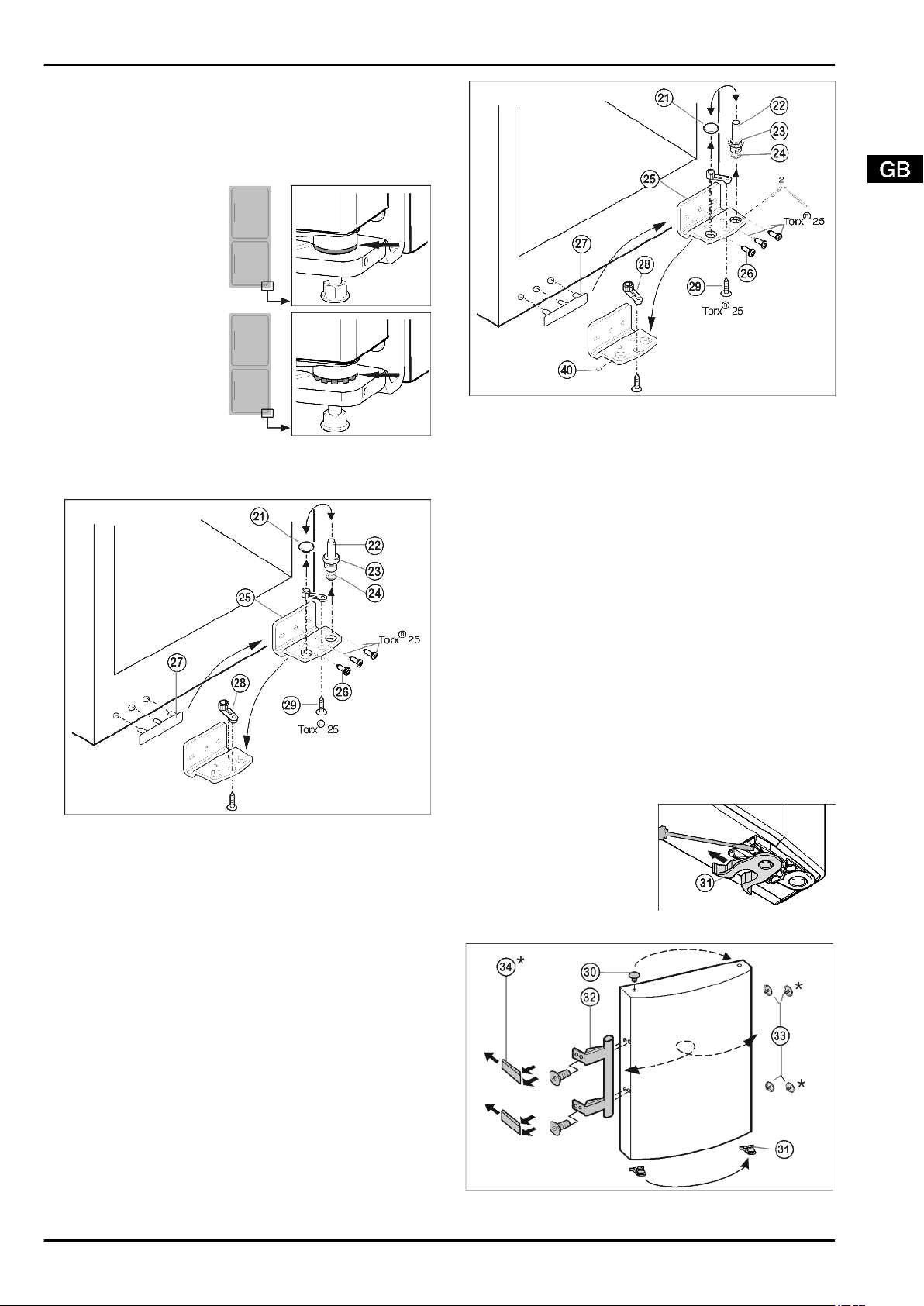
4.3.4 Distinguishing between bearing elements
Some appliances are height-adjustable, as can be noted from
the bearing pin in the lower turn hinge:
u
For appliances without
height adjustment,
continue with item
(see 4.3.5) .
u
For appliances with
height adjustment,
continue with item
(see 4.3.6) .
4.3.5 Transferring the lower bearing elements
For appliances without height adjustment
Fig. 6
u
Lift out the bearing pin
Fig. 6 (22)
together with washer
Fig. 6 (23)
and foot
Fig. 6 (24)
.
u
Lift off the stopper
Fig. 6 (21)
.
u
Unscrew
Fig. 6 (26)
the turn hinge
Fig. 6 (25)
.
u
Unscrew
Fig. 6 (29)
the bearing element
Fig. 6 (28)
, transfer
it to the opposite location hole of the turn hinge and screw it
firmly into place.
u
Carefully lift off the cover on the handle side
Fig. 6 (27)
and
transfer it to the opposite side.
u
Screw the turn hinge
Fig. 6 (25)
firmly into place on the new
hinge side, possibly using a cordless screwdriver (with
4 Nm).
u
Re-insert the stopper
Fig. 6 (21)
into the other hole.
u
Re-insert the bearing pin
Fig. 6 (22)
together with washer
and foot. In so doing, pay attention that the locating lug
points backwards
4.3.6 Changing the bearing parts
For appliances with height adjustment
Fig. 7
u
Using the accompanying Allen key, unscrew the threaded
pin
Fig. 7 (40)
by about 1 turn.
u
Turn and lift out the bearing pin
Fig. 7 (22)
together with the
washer
Fig. 7 (23)
and adjustable-height foot
Fig. 7 (24)
.
u
Lift out the stopper
Fig. 7 (21)
.
u
Unscrew
Fig. 7 (26)
the turn hinge
Fig. 7 (25)
.
u
Fully unscrew the threaded pin
Fig. 7 (40)
and screw it in on
the opposite side, at the turn hinge, until it is flush outside
with the turn hinge.
u
Unscrew
Fig. 7 (29)
the bearing element
Fig. 7 (28)
, transfer
it to the opposite location hole of the turn hinge and screw it
firmly into place.
u
Re-insert the stopper
Fig. 7 (21)
into the other hole.
u
Carefully lift off the cover on the handle side
Fig. 7 (27)
and
transfer it to the opposite side.
u
Screw the turn hinge
Fig. 7 (25)
firmly into place on the new
hinge side, possibly using a cordless screwdriver (with
4 Nm).
u
Screw the bearing pin
Fig. 7 (22)
into place again, complete
with washer and adjustable-height foot.
u
Tighten the threaded pin
Fig. 7 (40)
.
4.3.7 Transferring the handles
On both the upper and lower door:
u
Transfer the spring clamp
Fig. 8 (31)
: Depress the
latch nose and pull the
spring clamp off over it.
u
Slide the spring clamp
into place on the new
hinge side until it clicks
into place.
Fig. 8
Fig. 9
Putting into operation
* Depending on model and options 7
Loading ...
Loading ...
Loading ...