
Air-Conditioners
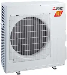
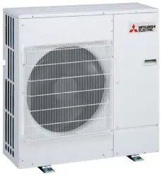
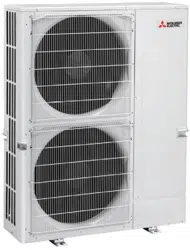
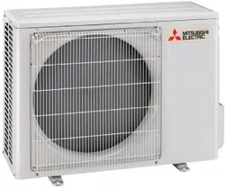
PUMY-SP112, SP125, SP140VKMD
PUMY-SP112, SP125, SP140YKMD
For use with R410A
INSTALLATION MANUAL
For safe and correct use, read this manual and the indoor unit installation manual thoroughly before installing
the air-conditioner unit.
English (GB)
FOR INSTALLER
RG79Y960H01.indb 1 2018/02/09 14:30:58
2
GB
Warning:
• The unit must not be installed by the user. Ask a dealer or an authorized
techniciantoinstalltheunit.Iftheunitisinstalledincorrectly,waterleakage,
electricshock,orremayresult.
• Thisapplianceisintendedtobeusedbyexpertortrainedusersinshops,in
lightindustryandonfarms,orforcommercialusebylaypersons.
• Forinstallationwork,followtheinstructionsintheInstallationManualand
usetoolsandpipecomponentsspecicallymadeforusewithR410Arefrig-
erant.TheR410ArefrigerantintheHFCsystemispressurized1.6timesthe
pressureofusualrefrigerants.IfpipecomponentsnotdesignedforR410A
refrigerantareusedandtheunitisnotinstalledcorrectly,thepipesmayburst
andcausedamageorinjuries.Inaddition,waterleakage,electricshock,or
remayresult.
• Theunitmustbeinstalledaccordingtotheinstructionsinordertominimize
theriskofdamagefromearthquakes,typhoons,orstrongwinds.Anincor-
rectlyinstalledunitmayfalldownandcausedamageorinjuries.
• Theunitmustbesecurelyinstalledonastructurethatcansustainitsweight.
Iftheunitismountedonanunstablestructure,itmayfalldownandcause
damage
orinjuries.
• Iftheairconditionerisinstalledinasmallroom,measuresmustbetakento
preventtherefrigerantconcentrationintheroomfromexceedingthesafety
limitintheeventofrefrigerantleakage.Consultadealerregardingtheappro-
priatemeasurestopreventtheallowableconcentrationfrombeingexceeded.
Shouldtherefrigerantleakandcausetheconcentrationlimittobeexceeded,
hazardsduetolackofoxygenintheroommayresult.
• Ventilatetheroomifrefrigerantleaksduringoperation.Ifrefrigerantcomes
intocontactwithaame,poisonousgaseswillbereleased.
• Allelectricworkmustbeperformedbyaqualiedtechnicianaccordingto
localregulationsandtheinstructionsgiveninthismanual.Theunitsmustbe
poweredbydedicatedpowerlinesandthecorrectvoltageandcircuitbreakers
mustbeused.Powerlineswithinsufcientcapacityorincorrectelectrical
workmayresultinelectricshockorre.
• UseC1220copperphosphorus,forcopperandcopperalloyseamlesspipes,
toconnecttherefrigerantpipes.Ifthepipesarenotconnectedcorrectly,the
unitwillnotbeproperlygroundedandelectricshockmayresult.
• Useonlyspeciedcablesforwiring.Thewiringconnectionsmustbemade
securelywith notension appliedontheterminalconnections. Also,never
splicethecablesforwiring(unlessotherwiseindicatedinthisdocument).
Failuretoobservetheseinstructionsmayresultinoverheatingorare.
• Theterminalblockcoverpaneloftheoutdoorunitmustbermlyattached.If
thecoverpanelismountedincorrectlyanddustandmoistureentertheunit,
electricshockorremayresult.
• Theapplianceshallbeinstalledinaccordancewithnationalwiringregulations.
• Ifthesupplycordisdamaged,itmustbereplacedbythemanufacturer,its
serviceagentorsimilarlyqualiedpersonsinordertoavoidahazard.
• Wheninstallingorrelocating,orservicingtheairconditioner,useonlythe
speciedrefrigerant(R410A)tochargetherefrigerantlines.Donotmixitwith
anyotherrefrigerantanddonotallowairtoremaininthelines.
Ifairismixedwiththerefrigerant,thenitcanbethecauseofabnormalhigh
pressure in the refrigerant line, and may result in an explosion and other
hazards.
Theuseofanyrefrigerantotherthanthatspeciedforthesystemwillcause
mechanical failure or systemmalfunctionor
unit breakdown.Intheworst
case,thiscouldleadtoaseriousimpedimenttosecuringproductsafety.
• UseonlyaccessoriesauthorizedbyMitsubishiElectricandaskadealeroran
authorizedtechniciantoinstallthem.Ifaccessoriesareincorrectlyinstalled,
waterleakage,electricshock,orremayresult.
• Donotaltertheunit.Consultadealerforrepairs.Ifalterationsorrepairsare
notperformedcorrectly,waterleakage,electricshock,orremayresult.
• Theusershouldneverattempttorepairtheunitortransferittoanotherloca-
tion.Iftheunitisinstalledincorrectly,waterleakage,electricshock,orre
mayresult.Iftheairconditionermustberepairedormoved,askadealeror
anauthorizedtechnician.
• Afterinstallationhasbeencompleted,checkforrefrigerantleaks.Ifrefriger-
antleaksintotheroomandcomesintocontactwiththeameofaheateror
portablecookingrange,poisonousgaseswillbereleased.
1. Safetyprecautions
► Beforeinstallingtheunit,makesureyoureadallthe“Safetyprecau-
tions”.
► Pleasereporttoortakeconsentbythesupplyauthoritybeforeconnec-
tiontothesystem.
Conrmationofpartsattached
In addition to this manual, the following part is supplied with the outdoor unit.
It is used for grounding the S terminal of transmission terminal block TB7. For details
refer to “6. Electrical work”.
Caution:
• DonotventR410Aintotheatmosphere.
1. Safety precautions .....................................................................................2
2. Installation location ....................................................................................4
3. Installing the outdoor unit ..........................................................................7
4. Installing the refrigerant piping ..................................................................7
5. Drainage piping work ...............................................................................15
6. Electrical work .........................................................................................15
7. Test run ....................................................................................................24
8. Special functions .....................................................................................25
9. Installation and operation manual for demand response (DRED) ...........26
Grounding lead wire
After installation work has been completed, explain the “Safety Precautions,” use, and
maintenance of the unit to the customer according to the information in the Operation
Manual and perform the test run to ensure normal operation. Both the Installation
Manual and Operation Manual must be given to the user for keeping. These manuals
must be passed on to subsequent users.
: Indicates a part which must be grounded.
Warning:
Carefullyreadthelabelsafxedtothemainunit.
Contents
Warning:
Describesprecautionsthatmustbeobservedtopreventdangerofinjuryor
deathtotheuser.
Caution:
Describesprecautionsthatmustbeobservedtopreventdamagetotheunit.
RG79Y960H01.indb 2 2018/02/09 14:30:58
3
GB
1. Safetyprecautions
1.3. Beforeelectricwork
Caution:
• Besuretoinstallcircuitbreakers.Ifnotinstalled,electricshockmayresult.
• Forthepowerlines,usestandardcablesofsufcientcapacity.Otherwise,a
shortcircuit,overheating,orremayresult.
• Wheninstalling the powerlines,do notapplytension tothecables. Ifthe
connectionsareloosened,thecablescansnaporbreakandoverheatingor
remayresult.
1.4. Beforestartingthetestrun
Caution:
• Turnonthemainpowerswitchmorethan12hoursbeforestartingoperation.
Startingoperationjustafterturningonthepowerswitchcanseverelydamage
theinternalparts.Keepthemainpowerswitchturnedonduringtheoperation
season.
• Beforestartingoperation,checkthatallpanels,guardsandotherprotective
partsarecorrectlyinstalled.Rotating,hot,orhighvoltagepartscancause
injuries.
• Donottouchanyswitchwithwethands.Electricshockmayresult.
• Besuretogroundtheunit.Donotconnectthegroundwiretogasorwater
pipes,lightningrods,ortelephonegroundinglines.Iftheunitisnotproperly
grounded,electricshockmayresult.
• Usecircuitbreakers(groundfaultinterrupter,isolatingswitch(+Bfuse),and
moldedcasecircuitbreaker)withthespeciedcapacity.Ifthecircuitbreaker
capacityislargerthanthespeciedcapacity,breakdownorremayresult.
• Do not touch the refrigerant pipes with bare hands during operation. The
refrigerantpipesarehotorcolddependingontheconditionoftheowing
refrigerant.Ifyoutouchthepipes,burnsorfrostbitemayresult.
• Afterstoppingoperation,besuretowaitatleastveminutesbeforeturning
offthemainpowerswitch.Otherwise,waterleakageorbreakdownmayresult.
1.5. UsingR410Arefrigerantairconditioners
Caution:
• UseC1220copperphosphorus,forcopperandcopperalloyseamlesspipes,
toconnecttherefrigerantpipes.Makesuretheinsidesofthepipesareclean
anddonotcontainanyharmfulcontaminantssuchassulfuriccompounds,
oxidants,debris,ordust.Usepipeswiththespeciedthickness.(Referto
4.1.)NotethefollowingifreusingexistingpipesthatcarriedR22refrigerant.
- Replacetheexistingarenutsandarethearedsectionsagain.
- Do not use thin pipes. (Refer to 4.1.)
• Storethepipestobeusedduringinstallationindoorsandkeepbothendsof
thepipessealeduntiljustbeforebrazing.(Leaveelbowjoints,etc.intheir
packaging.)Ifdust,debris,ormoistureenterstherefrigerantlines,oildete-
riorationorcompressorbreakdownmayresult.
• Useesteroil,etheroil,alkylbenzeneoil(smallamount)astherefrigeration
oilappliedtothearedsections.Ifmineraloilismixedintherefrigeration
oil,oildeteriorationmayresult.
• DonotuserefrigerantotherthanR410Arefrigerant.Ifanotherrefrigerantis
used,thechlorinewillcausetheoiltodeteriorate.
• UsethefollowingtoolsspecicallydesignedforusewithR410Arefrigerant.
The following tools are necessary to use R410Arefrigerant. Contact your
nearestdealerforanyquestions.
Tools (for R410A)
Gauge manifold Flare tool
Charge hose Size adjustment gauge
Gas leak detector Vacuum pump adapter
Torque wrench Electronic refrigerant charging scale
• Besuretousethecorrecttools.Ifdust,debris,ormoistureenterstherefriger-
antlines,refrigerationoildeteriorationmayresult.
• Donotuseachargingcylinder.Ifachargingcylinderisused,thecomposition
oftherefrigerantwillchangeandtheefciencywillbelowered.
1.2. Beforeinstallation(relocation)
Caution:
• Beextremelycarefulwhentransportingtheunits.Twoormorepersonsare
neededtohandletheunit,asitweighs20kgormore.Donotgraspthepack-
agingbands.Wearprotectiveglovestoremovetheunitfromthepackaging
andtomoveit,asyoucaninjureyourhandsonthensorotherparts.
• Besuretosafelydisposeofthepackagingmaterials.Packagingmaterials,such
asnailsandothermetalorwoodenpartsmaycausestabsorotherinjuries.
• Thebaseandattachmentsoftheoutdoorunitmustbeperiodicallychecked
forlooseness,cracksorotherdamage.Ifsuchdefectsareleftuncorrected,
theunitmayfalldownandcausedamageorinjuries.
• Donotcleantheairconditionerunitwithwater.Electricshockmayresult.
• Tightenallarenutstospecicationusingatorquewrench.Iftightenedtoo
much,thearenutcanbreakafteranextendedperiodandrefrigerantcan
leakout.
1.1. Beforeinstallation
Caution:
• Donotusetheunitinanunusualenvironment.Iftheairconditionerisinstalled
inareasexposedtosteam,volatileoil(includingmachineoil),orsulfuricgas,
areasexposedtohighsaltcontentsuchastheseaside,orareaswherethe
unitwillbecoveredbysnow,theperformancecanbesignicantlyreduced
andtheinternalpartscanbedamaged.
• Donotinstalltheunitwherecombustiblegasesmayleak,beproduced,ow,
oraccumulate.Ifcombustiblegasaccumulatesaroundtheunit,reorexplo-
sionmayresult.
• Theoutdoorunitproducescondensationduringtheheatingoperation.Make
suretoprovidedrainagearoundtheoutdoorunitifsuchcondensationislikely
tocausedamage.
• Wheninstallingtheunitinahospitalorcommunicationsofce,bepreparedfor
noiseandelectronicinterference.Inverters,homeappliances,high-frequency
medicalequipment,andradiocommunicationsequipmentcancausetheair
conditionertomalfunctionorbreakdown.Theairconditionermayalsoaffect
medicalequipment,disturbingmedicalcare,andcommunicationsequipment,
harmingthescreendisplayquality.
RG79Y960H01.indb 3 2018/02/09 14:30:58
4
GB
2. Installationlocation
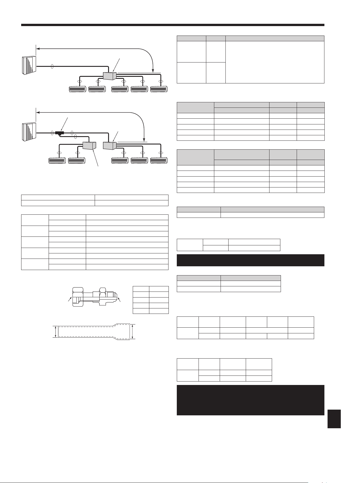
2.1. Refrigerantpipe
Refer to Fig. 4-1, 4-2.
2.2. Choosingtheoutdoorunitinstallationlocation
• Avoidlocationsexposedtodirectsunlightorothersourcesofheat.
• Selectalocationfromwhichnoiseemittedbytheunitwillnotinconvenienceneigh-
bors.
• Selectalocationpermittingeasywiringandpipeaccesstothepowersourceand
indoor unit.
• Avoidlocationswherecombustiblegasesmayleak,beproduced,ow,oraccumu-
late.
• Notethatwatermaydrainfromtheunitduringoperation.
• Selectalevellocationthatcanbeartheweightandvibrationoftheunit.
• Avoidlocationswheretheunitcanbecoveredbysnow.Inareaswhereheavysnow
fall is anticipated, special precautions such as raising the installation location or
installing a hood on the air intake must be taken to prevent the snow from block-
ingtheairintakeorblowingdirectlyagainstit.Thiscanreducetheairowanda
malfunction may result.
• Avoidlocationsexposedtooil,steam,orsulfuricgas.
• Usethetransportationhandlesoftheoutdoorunittotransporttheunit.Iftheunit
iscarriedfromthebottom,handsorngersmaybepinched.
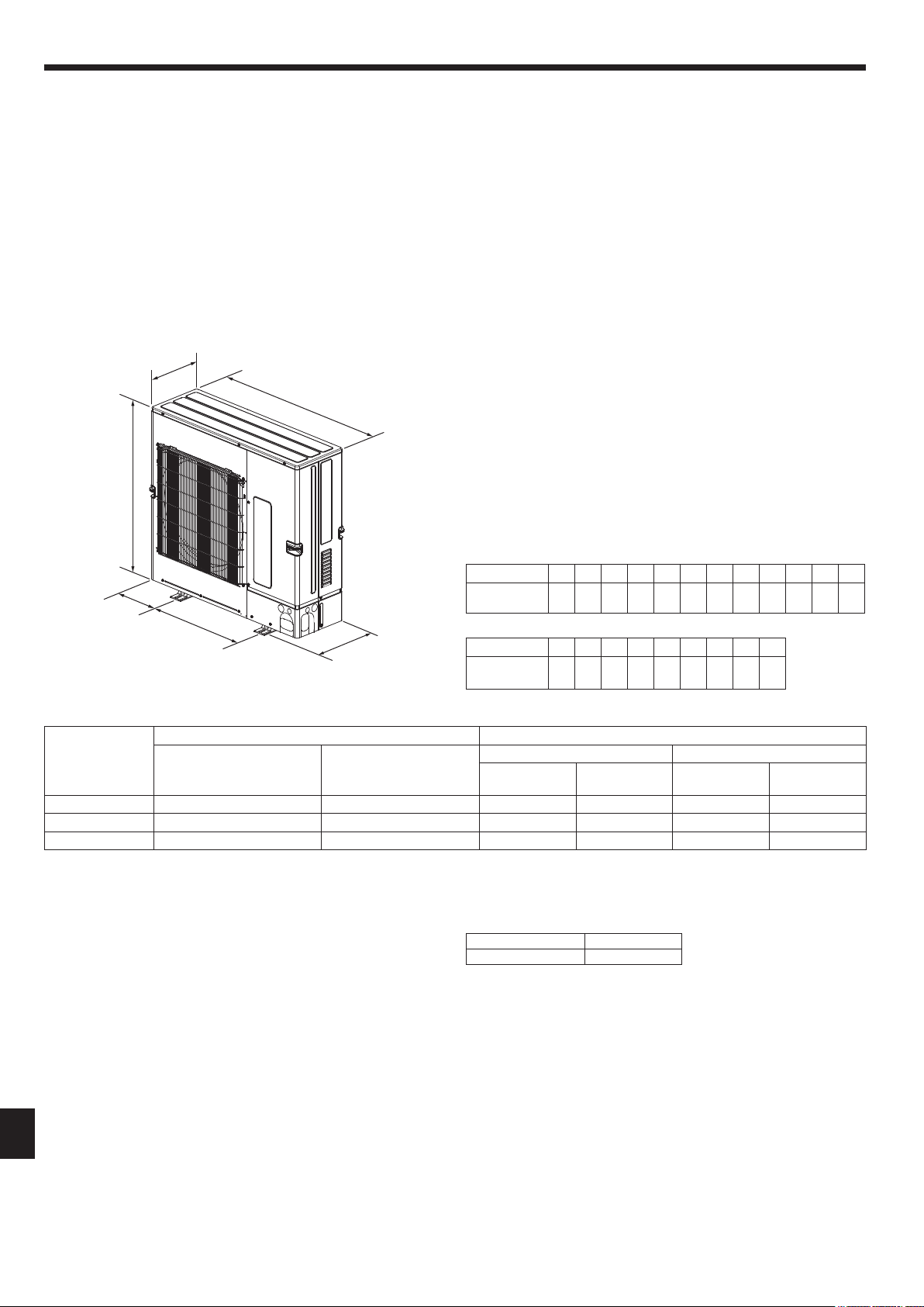
2.3. Outlinedimensions(Outdoorunit)(Fig.2-1)
Constraints on indoor unit installation
You should note that indoor units that can be connected to this outdoor unit are the
following models.
• Indoorunitswithmodelnumbers15-140canbeconnected.
When using Branch box, Indoor units with model numbers 22-100 can be connected.
Refer to the table 1 below for possible room, indoor unit combinations.
Verication
The rated capacity should be determined by observing the table below. The unit’s
quantities are limited as shown in the following table 2. For the next step, make
sure that the total rated capacity selected will stay in a range of 50% – 130% of the
outdoor unit capacity.
• PUMY-SP112 6.3–16.2kW
• PUMY-SP125 7.1–18.2kW
• PUMY-SP140 8.0–20.2kW
Table 1-1 City Multi indoor units
Indoor unit type
15 20 25 32 40 50 63 71 80 100 125 140
Rated capacity
(Cooling) (kW)
1.7 2.2 2.8 3.6 4.5 5.6 7.1 8.0 9.0 11.2 14.0 16.0
Table 1-2 M series, P series, S series
Indoor unit type
22 25 35 42 50 60 71 80 100
Rated capacity
(Cooling) (kW)
2.2 2.5 3.5 4.2 5.0 6.0 7.1 8.0 10.0
Table 2 Connectable indoor units quantities
Model Only system Mixed system
Only City Multi indoor units
(Connection without Branch box)
Only M series, P series,
S series indoor units
(Connection with Branch box)
One Branch box Two Branch box
Connection with
Branch box
City Multi indoor
units
Connection with
Branch box
City Multi indoor
units
PUMY-SP112 1-9 2-8 Max. 5 Max. 5 Max. 7 or 8*1 Max. 3 or 2*1
PUMY-SP125 1-10 2-8 Max. 5 Max. 5 Max. 8 Max. 3
PUMY-SP140 1-12 2-8 Max. 5 Max. 5 Max. 8 Max. 3
(mm)
Fig.2-1
370
1050
225
600
981
330+25
*1 When connecting 7 indoor units via branch box, connectable citymulti indoor units
are 3; connecting 8 indoor units via branch box, connectable citymulti indoor units
are 2.
Table 3 Connectable Branch box quantities
Model Branch box
PUMY-SP112/125/140 1-2
Combinations in which the total capacity of indoor units exceeds the capacity of the
outdoor unit will reduce the cooling capacity of each indoor unit below their rated
cooling capacity. Thus, combine indoor units with an outdoor unit within the outdoor
unit’s capacity, if possible.
RG79Y960H01.indb 4 2018/02/09 14:30:59
5
GB
2. Installationlocation
2.4. ConnectingaPEFY-P∙VMA3-E
WhenusingaPEFY-P∙VMA3-E,usethefollowingcombinationsfortheconnectedindoorunits.
PUMY-SP112 PUMY-SP125 PUMY-SP140
OK
PEFY-P25VMA3-E × 2
+
PEFY-P32VMA3-E × 2
PEFY-P25VMA3-E × 1
+
PEFY-P32VMA3-E × 3
PEFY-P32VMA3-E × 2
+
PEFY-P40VMA3-E × 2
NO
All combinations excluding the above
combinations
All combinations excluding the above
combinations
All combinations excluding the above
combinations
Ex. 1: PEFY-P25VMA3-E × 2
+
PEFY-P32VMA-E × 2
Ex. 2: PEFY-P25VMA3-E × 2
+
PEFY-P32VMA3-E × 1
Ex. 3: PEFY-P32VMA3-E × 4
(AcombinationforaPUMY-SP125)
Ex. 4: PEFY-P25VMA3-E × 2
+
PEFY-P32VMA3-E × 2
+
MSZ-FH25VE × 1
Ex. 1: PEFY-P32VMA3-E × 3
+
PEFY-P32VMA-E × 1
Ex. 2: PEFY-P32VMA3-E × 3
Ex. 3: PEFY-P25VMA3-E × 2
+
PEFY-P32VMA3-E × 2
(AcombinationforaPUMY-SP112)
Ex. 4: PEFY-P32VMA3-E × 3
+
PLFY-P20VFM-E × 1
+
SEZ-KD25VA × 1
Ex. 1: PEFY-P32VMA3-E × 3
+
PEFY-P40VMA-E × 1
Ex. 2: PEFY-P32VMA3-E × 2
+
PEFY-P40VMA3-E × 1
Ex. 3: PEFY-P32VMA3-E × 4
(AcombinationforaPUMY-SP125)
Ex. 4: PEFY-P32VMA3-E × 3
+
PCFY-P40VKM-E × 1
+
MSZ-FH25VE × 1
Ex. 1: A ceiling-concealed unit other than a VMA3 series is selected. Combinations
with a ceiling-concealed different series are not possible.
Ex. 2: The number of units is incorrect.
Ex. 3: The combination is for a unit with a different capacity.
Ex. 4: The combination is not an “OK” combination.
RG79Y960H01.indb 5 2018/02/09 14:30:59
6
GB
2. Installationlocation
2.5. Ventilationandservicespace
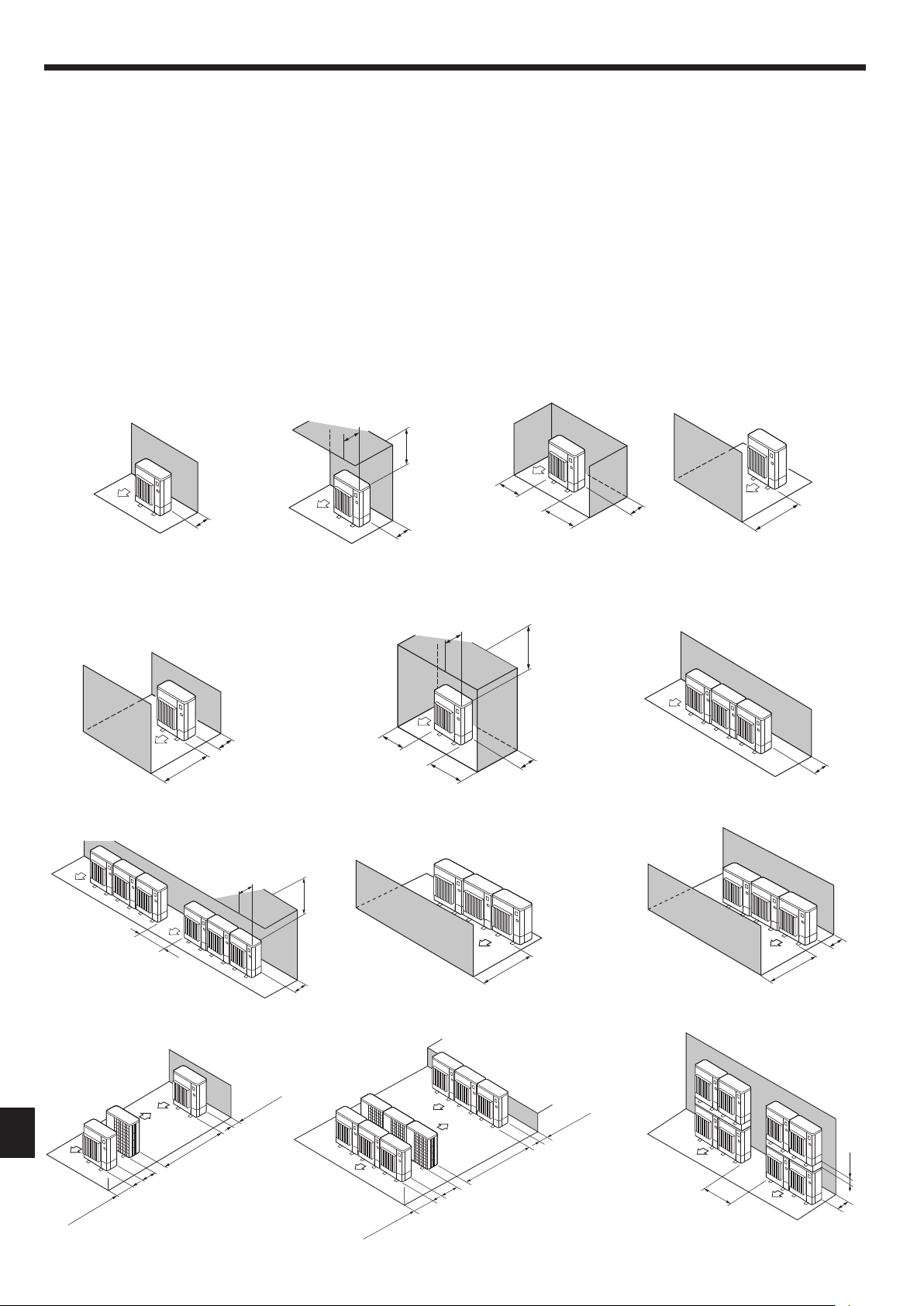
2.5.1. Wheninstallingasingleoutdoorunit
Minimum dimensions are as follows, except for Max., meaning Maximum dimen-
sions, indicated.
Refertotheguresforeachcase.
1 Obstacles at rear only (Fig. 2-2)
2 Obstacles at rear and above only (Fig. 2-3)
3 Obstacles at rear and sides only (Fig. 2-4)
4 Obstacles at front only (Fig. 2-5)
∗ When using an optional air outlet guide, the clearance is 500 mm or more.
5 Obstacles at front and rear only (Fig. 2-6)
∗ When using an optional air outlet guide, the clearance is 500 mm or more.
6 Obstacles at rear, sides, and above only (Fig. 2-7)
• Donotinstalltheoptionalairoutletguidesforupwardairow.
2.5.2. Wheninstallingmultipleoutdoorunits
Leave 25 mm space or more between the units.
1 Obstacles at rear only (Fig. 2-8)
2 Obstacles at rear and above only (Fig. 2-9)
• Nomorethan3unitsmustbeinstalledsidebyside.Inaddition,leavespaceasshown.
• Donotinstalltheoptionalairoutletguidesforupwardairow.
3 Obstacles at front only (Fig. 2-10)
∗ When using an optional air outlet guide, the clearance is 1000 mm or more.
4 Obstacles at front and rear only (Fig. 2-11)
∗ When using an optional air outlet guide, the clearance is 1000 mm or more.
5 Single parallel unit arrangement (Fig. 2-12)
∗ Whenusinganoptionalairoutletguideinstalledforupwardairow,theclearanceis1000mm
or more.
6 Multiple parallel unit arrangement (Fig. 2-13)
∗ Whenusinganoptionalairoutletguideinstalledforupwardairow,theclearanceis1500mm
or more.
7 Stacked unit arrangement (Fig. 2-14)
• Theunitscanbestackedupto2unitshigh.
• Nomorethan2stackedunitsmustbeinstalledsidebyside.Inaddition,leavespaceasshown.
150
Fig.2-2
Max.300
1500
500
1500
Fig.2-9
1000
300
Fig.2-3
Max.500
Fig.2-4
300
200
200
Fig.2-5
1000*
Fig.2-6
1000*
150
Fig.2-7
250
250
500
Max.500
Fig.2-8
300
Fig.2-10
1500*
Fig.2-11
1500*
500
Fig.2-12
1000
600
2000*
150
Fig.2-13
1500
600
3000*
500
Fig.2-14
1500
800
150
1500
UNIT:mm
RG79Y960H01.indb 6 2018/02/09 14:31:00
7
GB
B
D
600 600
33025
370
225 225
1050
2.5.3. Windylocationinstallation
When installing the outdoor unit on a rooftop or other location unprotected from the
wind, situate the air outlet of the unit so that it is not directly exposed to strong winds.
Strongwindenteringtheairoutletmayimpedethenormalairowandamalfunction
may result.
The following shows two examples of precautions against strong winds.
1 Install an optional air guide if the unit is installed in a location where strong winds
from a typhoon, etc. may directly enter the air outlet. (Fig. 2-15)
A Air guide
2 Position the unit so that the air outlet blows perpendicularly to the seasonal wind
direction, if possible. (Fig. 2-16)
B Wind direction
2. Installationlocation
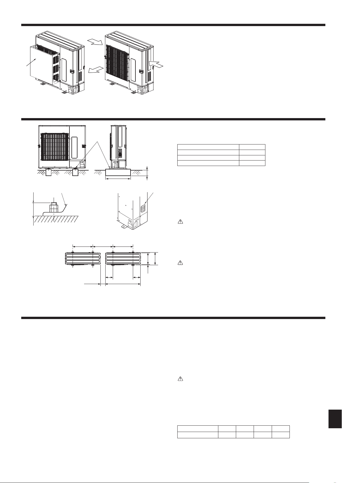
3. Installingtheoutdoorunit
• Besuretoinstalltheunitinasturdy,levelsurfacetopreventrattlingnoisesduring
operation. (Fig. 3-1)
<Foundationspecications>
Foundation bolt M10(3/8″)
Thickness of concrete 120 mm
Length of bolt 70 mm
Weight-bearing capacity 320 kg
• Makesurethatthelengthofthefoundationboltiswithin30mmofthebottomsurface
of the base.
• Securethebaseoftheunitrmlywithfour-M10foundationboltsinsturdylocations.
Installing the outdoor unit
• Donotblockthevent.Iftheventisblocked,operationwillbehinderedandbreak-
down may result.
• Inadditiontotheunitbase,usetheinstallationholesonthebackoftheunittoattach
wires,etc.,ifnecessarytoinstalltheunit.Useself-tappingscrews(ø5× 15 mm or
less) and install on site.
Warning:
• Theunitmustbesecurelyinstalledonastructurethatcansustainitsweight.
Iftheunitismountedonanunstablestructure,itmayfalldownandcause
damageorinjuries.
• Theunitmustbeinstalledaccordingtotheinstructionsinordertominimize
theriskofdamagefromearthquakes,typhoons,orstrongwinds.Anincor-
rectlyinstalledunitmayfalldownandcausedamageorinjuries.
Caution:
• Installunitonarigidstructuretopreventexcessiveoperationsoundorvibra-
tion.
Fig.3-1
4. Installingtherefrigerantpiping
4.1. PrecautionsfordevicesthatuseR410Arefrigerant
• Referto1.5.forprecautionsnotincludedbelowonusingairconditionerswith
R410Arefrigerant.
• Useesteroil,etheroil,alkylbenzeneoil(smallamount)astherefrigeration
oilappliedtothearedsections.
• UseC1220copperphosphorus,forcopperandcopperalloyseamlesspipes,
toconnecttherefrigerantpipes.Userefrigerantpipeswiththethicknesses
speciedinthetabletothebelow.Makesuretheinsidesofthepipesareclean
anddonotcontainanyharmfulcontaminantssuchassulfuriccompounds,
oxidants,debris,ordust.
Warning:
When installing or relocating, or servicing the air conditioner,use only the
speciedrefrigerant(R410A)tochargetherefrigerantlines.Donotmixitwith
anyotherrefrigerantanddonotallowairtoremaininthelines.
Ifairismixedwiththerefrigerant,thenitcanbethecauseofabnormalhigh
pressureintherefrigerantline,andmayresultinanexplosionandotherhazards.
Theuseofanyrefrigerantotherthanthatspeciedforthesystemwillcause
mechanicalfailureorsystemmalfunctionorunitbreakdown.Intheworstcase,
thiscouldleadtoaseriousimpedimenttosecuringproductsafety.
Pipe size (mm) ø6.35 ø9.52 ø12.7 ø15.88
Thickness (mm) 0.8 0.8 0.8 1.0
• Donotusepipesthinnerthanthosespeciedabove.
• ThethicknesseslistedinthetableabovearebasedonJapanesestandards.
Usepipeswithamaximumworkingpressureof4.15MPa[601PSIG]or
higheraccordingtolocalstandards.
AM10(3/8")bolt
B Base
C As long as possible.
(mm)
D Vent
E Set deep in the ground.
Min. 500
Min. 25*
* When installing a single outdoor unit, the clearance is 15 mm or more.
Max. 30
Fig.2-15 Fig.2-16
B
A
E
C
A
RG79Y960H01.indb 7 2018/02/09 14:31:04
8
GB
B
A
H
B C
L
r
D
e
a
h
b c d
C
C
B
A
A
A
a
b
c d
C
D
e f
H
h
L
r
C C C
C C
C C
C
4. Installingtherefrigerantpiping
A Outdoor unit
B First branch (CMY)
C Indoor unit
D Cap
A+B+C+D+a+b+c+d+e [ 120 m
L = A+B+C+D+e [ 70 m
ℓ=B+C+D+e[ 50 m
H [ 50 m (Outdoor lower H [ 30 m)
h [ 15 m
A+a+b+c+d+e+f [ 120 m
L = A+f [70m,ℓ=f[ 50 m
H [ 50 m (Outdoor lower H [ 30 m)
h [ 15 m
Fig.4-1
4.1.2. ConnectionwithBranchbox(Fig.4-2)
Flared connections
• Thisunithasaredconnectionsoneachindoorunitandbranchboxandoutdoor
unit sides.
• Removethevalvecoveroftheoutdoorunit,thenconnectthepipe.
• Refrigerantpipesareusedtoconnectthebranchboxandoutdoorunit.
Fig.4-2
B
C
B
C C C
C
C C
C
L
I
h2
b2
b1
c1
a6a5
a4a3a2
h3
h1
H
a1
a7 a8
D
A
A Outdoor unit
B Branch box (PAC-MK∙BC)
C Indoor unit
D First branch (MSDD)
Permissible
length
(one-way)
Total piping length
c1 + b1 + b2 + a1 + a2 + a3 + a4 + a5 + a6 + a7 + a8 [ 120 m
Farthest piping length (L)
c1 + b2 + a8 [ 80 m
Piping length between outdoor unit and branch boxes
c1 + b1 + b2 [ 55 m
Farthestbranchboxfromtherstjoint(b2)
b2 [ 50 m
Farthest piping length after branch box (l)
a8 [ 25 m
Total piping length between branch boxes and indoor units
a1 + a2 + a3 + a4 + a5 + a6 + a7 + a8 [ 95 m
Permissible
height
difference
(one-way)
Inindoor/outdoorsection(H)*1
H [ 50 m (In case of outdoor unit is set higher than indoor unit)
H [ 30 m (In case of outdoor unit is set lower than indoor unit)
Inbranchbox/indoorunitsection(h1)
h1 + h2 [ 15 m
In each branch unit (h2)
h2 [ 15 m
In each indoor unit (h3)
h3 [ 12 m
Numberofbends
| c1 + b1 + a1 |, | c1 + b1 + a2 |, | c1 + b1 + a3 |, | c1 + b1 + a4 |, | c1 + b1 + a5 |, | c1 +
b2 + a6 |, | c1 + b2 + a7 |, | c1 + b2 + a8 | [ 15
*1 Branch box should be placed within the level between the outdoor unit and indoor units.
A (mm)
A
Liquid pipe
B
Gas pipe
ø9.52 ø15.88
L: The farthest piping length from the outdoor unit to an indoor unit.
B, C, D (mm)
A
Liquid pipe
B
Gas pipe
ø9.52 ø15.88
L: The farthest piping length from the outdoor unit to an indoor unit.
a, b, c, d, e, f (mm)
D
Model number
A
Liquid pipe
B
Gas pipe
15, 20, 25, 32, 40, 50
a, b, c, d, e, f
[
30 m
ø6.35
ø12.7
a,b,c,d,e,f˃30m ø9.52*1
63, 71, 80, 100, 125, 140 ø9.52 ø15.88
*1Ifthepipinglengthaftertherstjointexceeds30m,useapipesizeofø9.52for
the pipes of the system that exceeds 30 m.
E
Branch kit model
CMY-Y62-G-E
F
4-Branching header
G
8-Branching header
CMY-Y64-G-E CMY-Y68-G-E
* WhenconnectingtheCONNECTIONKIT(PAC-LV11M-J)andanM-seriesindoor
unit,refertotheinstallationmanualfortheCONNECTIONKITwhenselectingthe
pipe size and piping length.
4.1.1. ConnectionwithoutBranchbox(Fig.4-1)
RG79Y960H01.indb 8 2018/02/09 14:31:05
9
GB
A
A
A
B B B B B
L
Selectingpipesize(Fig.4-3)
A B
Liquid (mm) ø9.52
The piping connection size differs according to the type
and capacity of indoor units. Match the piping connec-
tion size of branch box with indoor unit.
If the piping connection size of branch box does not
match the piping connection size of indoor unit, use
optional different-diameter (deformed) joints to the
branch box side. (Connect deformed joint directly to
the branch box side.)
Gas (mm) ø15.88
L: The farthest piping length for the main pipes from the outdoor unit to the branch
box.
Different-diameterjoint(optionalparts)(Fig.4-4)
Model name
Connected pipes diameter Diameter A Diameter B
mm mm mm
MAC-A454JP ø9.52→ø12.7 ø9.52 ø12.7
MAC-A455JP ø12.7→ø9.52 ø12.7 ø9.52
MAC-A456JP ø12.7→ø15.88 ø12.7 ø15.88
PAC-493PI ø6.35→ø9.52 ø6.35 ø9.52
PAC-SG76RJ-E ø9.52→ø15.88 ø9.52 ø15.88
Different-diameterjoint(optionalparts)(Fig.4-5)
Model name
Connected pipes diameter
Outside
Diameter A
Inside
Diameter B
mm mm mm
PAC-SG78RJB-E
ø9.52→ø12.7
ø9.52 ø12.7
PAC-SG79RJB-E
ø12.7→ø9.52
ø12.7 ø9.52
PAC-SG80RJB-E
ø12.7→ø15.88
ø12.7 ø15.88
PAC-SG77RJB-E
ø6.35→ø9.52
ø6.35 ø9.52
PAC-SG76RJB-E
ø9.52→ø15.88
ø9.52 ø15.88
2-branchespipe(Joint):Optionalparts(Accordingtotheconnectionmethod,
youcanchoosethefavoriteone.)
Model name Connection method
MSDD-50AR-E are
■Installationprocedure(2branchespipe(Joint))
Refer to the installation manuals of MSDD-50AR-E.
■
Pipesize(Outdoorunit-Branchbox)
Pipe size
(ømm)
Liquid ø9.52
Gas ø15.88
The lineup of aconnectable indoor unit depends on a district/areas/
country.
■
Branchbox
Model name Numberofconnectedunits
PAC-MK3
✽
BC 3-branches (Max. 3 units)
PAC-MK5
✽
BC 5-branches (Max. 5 units)
Note:
✽
=0,1,2,....
ThePAC-MK31/32BCandPAC-MK51/52BCcannotbeconnected.
■
Pipesize(Branchbox–Indoorunit)CaseofMseriesorSseriesindoorunit
Indoor
unit type
(kW) 22 – 42 50 60 71 – 80
Pipe size
(ømm)
Liquid ø6.35 ø6.35 ø9.52
Gas ø9.52 ø12.7 ø15.88 ø15.88
* If the pipe size of indoor unit is different, use a different-diameter joint.
■
Pipesize(Branchbox–Indoorunit)CaseofPseriesindoorunit
Indoor
(kW) 35 – 50 60 – 100
unit type
Pipe size
(ømm)
Liquid ø6.35 ø9.52
Gas ø12.7 ø15.88
*1 The lineup of aconnectable indoor unit depends on a district/areas/
country.
*2 Whenusing35,50typeindoorunitofPseries,usethearenutattached
totheindoorunit.
Donotusethearenutintheindoorunitaccessory.Ifitisused,agas
leakageorevenapipeextractionmayoccur.
(1) Valve size for outdoor unit
For liquid ø9.52mm
For gas ø15.88mm
(2) Valve size for branch box
AUNIT
Liquid pipe ø6.35mm
Gas pipe ø9.52mm
BUNIT
Liquid pipe ø6.35mm
Gas pipe ø9.52mm
CUNIT
Liquid pipe ø6.35mm
Gas pipe ø9.52mm
DUNIT
Liquid pipe ø6.35mm
Gas pipe ø9.52mm
EUNIT
Liquid pipe ø6.35mm
Gas pipe ø12.7mm
* 3-branch type : only A, B, C unit
B
A
Fig.4-4
Fig.4-3
A
B B B B B
L
Branch box (PAC-MK∙BC)
■Incaseofusing1-branchbox
Flareconnectionemployed.(No.brazing)
■Incaseofusing2-branchboxes
Branchbox#1(PAC-MK∙BC)
2 branches pipe (joint) (MSDD)
: optional parts.
Branchbox#2(PAC-MK∙BC)
Conversion formula
1/4F ø6.35
3/8F ø9.52
1/2F ø12.7
5/8F ø15.88
3/4F ø19.05
4. Installingtherefrigerantpiping
Fig.4-5
A (outside) B (inside)
RG79Y960H01.indb 9 2018/02/09 14:31:05
10
GB
4. Installingtherefrigerantpiping
A
B
e1
d2
L2
d1
b1c1
c2 b2
H
h3
h1
C
D
a1
a2 a3
a4 a5 a6 a7 a8
E
E E
E E
F
F F F
F
L1
AOutdoorUnit
B First joint (CMY, MSDD)
C Branch header (CMY)
DBranchbox(PAC-MK∙BC)
E CityMulti Indoor unit
FM/S/PseriesIndoorunit
Permissible
length (One-way)
Total piping length
e1 + d1 + d2 + c1 + c2 + b1 + b2 + a1 + a2 + a3 + a4 + a5 + a6 + a7 + a8 [ 120 m
Farthest piping length (L1)
e1 + d2 + a1 or e1 + d1 + c1 + b2 [ 70 m
Farthest piping length. Via Branch box (L2)
e1 + d1 + c1 + b1 + a8 [ 80 m
Piping length between outdoor unit and branch box
e1 + d1 + c1 + b1 [ 55 m
Farthestpipinglengthfromtherstjoint
d1 + c1 + b1 or d2 + a1 [ 50 m
Farthest piping length after branch box
a8 [ 25 m
Total piping length between branch boxes and indoor units
a4 + a5 + a6 + a7 + a8 [ 95 m
Permissible
height difference
(One-way)
Inindoor/outdoorsection(H)*1
H [ 50 m (In case of outdoor unit is set higher than indoor unit)
H [ 30 m (In case of outdoor unit is set lower than indoor unit)
Inbranchbox/indoorunitsection(h1)
h1 [ 15 m
In each indoor unit (h3)
h3 [ 12 m
Numberofbends |e1 + d2 + a1|, |e1 + d2 + a2|, |e1 + d2 + a3|, |e1 + d1 + c2|, |e1 + d1 + c1 + b2|,
|e1 + d1 + c1 + b1 + a4|, |e1 + d1 + c1 + b1 + a5|, |e1 + d1 + c1 + b1 + a6|,
|e1 + d1 + c1 + b1 + a7|, |e1 + d1 + c1 + b1 + a8| [ 15
*1: Branch box should be placed within the level between the outdoor unit and indoor units.
4.1.3-2Incaseofusing2-branchboxes
A
B
d1
c1
L2
L1
c2
b2
b1
h1
h2
H
h3
C
D
D
a1
a2 a3
a4 a5 a6 a7 a8 a9 a10 a11
E
E E
F
F F
F F
F
F
F
AOutdoorUnit
B First joint (CMY, MSDD)
C Branch header (CMY)
DBranchbox(PAC-MK∙BC)
E CityMulti Indoor unit
FM/S/PseriesIndoorunit
Permissible
length (One-way)
Total piping length
d1 + c1 + c2 + b1 + b2 + a1 + a2 + a3 + a4 + a5 + a6 + a7 + a8 + a9 + a10 + a11
[
120 m
Farthest piping length (L1)
d1 + c1 + a1
[
70 m
Farthest piping length. Via Branch box (L2)
d1 + c2 + b2 + a11
[
80 m
Piping length between outdoor unit and branch boxes
d1 + c2 + b1 + b2
[
55 m
Farthestpipinglengthfromtherstjoint
c2 + b2 or c1 + a1
[
50 m
Farthest piping length after branch box
a11
[
25 m
Farthest branch box from outdoor unit
d1 + c2 + b2
[
55 m
Total piping length between branch boxes and indoor units
a4 + a5 + a6 + a7 + a8 + a9 + a10 + a11
[
95 m
Permissible
height difference
(One-way)
Inindoor/outdoorsection(H)*1
H
[
50 m (In case of outdoor unit is set higher than indoor unit)
H
[
30 m (In case of outdoor unit is set lower than indoor unit)
Inbranchbox/indoorunitsection(h1+h2)
h1 + h2
[
15 m
In each branch unit (h1)
h2
[
15 m
In each indoor unit (h3)
h3
[
12 m
Numberofbends
|d1 + c1 + a1|, |d1 + c1 + a2|, |d1 + c1 + a3|, |d1 + c2 + b1 + a4|, |d1 + c2 + b1 + a5|, |d1 + c2 + b1
+ a6|, |d1 + c2 + b1 + a7|, |d1 + c2 + b1 + a8|, |d1 + c2 + b2 + a9|, |d1 + c2 + b2 + a10|, |d1 + c2
+ b2 + a11|
[
15
*1: Branch box should be placed within the level between the outdoor unit and indoor units.
4.1.3. Mixedsystem(CityMultiindoorunitsandM/S/PseriesindoorunitsviaBranchbox)
4.1.3-1Incaseofusing1-branchbox
RG79Y960H01.indb 10 2018/02/09 14:31:05
11
GB
4. Installingtherefrigerantpiping
Branch box
Port A
Port B
Port C
Port D
Port E
Branchboxpipesize
4.1.3-3Selectingpipesize
Systempipesize
Pipesize
A, B, C, D, E
A
Liquid pipe
B
Gas pipe
ø9.52 ø15.88
L1: The farthest piping length from the outdoor unit to an indoor unit.
L2: The farthest piping length for the main pipes from the outdoor unit to the branch
box.
L3:Thefarthestpipinglengthfromtherstjoint.
a, b, c – j
Indoor unit series Model number
A
Liquid pipe
B
Gas pipe
City Multi
15 – 50
L3
[
30m
ø6.35
ø12.7
L3˃30m ø9.52*1
63 – 140
ø9.52 ø15.88
M series or S series
22 – 42
ø6.35 ø9.52
50
ø6.35 ø12.7
60
ø6.35 ø15.88
71, 80
ø9.52 ø15.88
P series
35 – 50
ø6.35 ø12.7
60 – 100
ø9.52 ø15.88
* If the pipe size of indoor unit is different, use a different-diameter joint.
*1 Ifthepipinglengthaftertherstjointexceeds30m,useapipesizeofø9.52for
the pipes of the system that exceeds 30 m.
2-branch joint CMY-Y62-G-E
4-branch header CMY-Y64-G-E
8-branch header CMY-Y68-G-E
Different-diameterjoint(optionalparts)(Fig.4-6)
Model name
Connected pipes diameter Diameter A Diameter B
mm mm mm
MAC-A454JP
ø9.52
→
ø12.7 ø9.52 ø12.7
MAC-A455JP
ø12.7
→
ø9.52 ø12.7 ø9.52
MAC-A456JP
ø12.7
→
ø15.88 ø12.7 ø15.88
PAC-493PI
ø6.35
→
ø9.52 ø6.35 ø9.52
PAC-SG76RJ-E
ø9.52
→
ø15.88 ø9.52 ø15.88
Different-diameterjoint(optionalparts)(Fig.4-7)
Model name
Connected pipes diameter
Outside
Diameter A
Inside
Diameter B
mm mm mm
PAC-SG78RJB-E
ø9.52
→
ø12.7 ø9.52 ø12.7
PAC-SG79RJB-E
ø12.7
→
ø9.52 ø12.7 ø9.52
PAC-SG80RJB-E
ø12.7
→
ø15.88 ø12.7 ø15.88
PAC-SG77RJB-E
ø6.35
→
ø9.52 ø6.35 ø9.52
PAC-SG76RJB-E
ø9.52
→
ø15.88 ø9.52 ø15.88
2-branch pipe (Joint): Optional parts (According to the connection method,
youcanchoosethefavoriteone.)
Model name
Connection method
MSDD-50AR-E
are
Branchbox
Model name
Numberofconnectedunits
PAC-MK3
✽
BC
3-branches (Max. 3 units)
PAC-MK5
✽
BC
5-branches (Max. 5 units)
Note:
✽
=0,1,2,....
ThePAC-MK31/32BCandPAC-MK51/52BCcannotbeconnected.
A
A
E
B
C
C D
D
a
b c
d e
f g h i j
E
E E
E E F
F F F
F
L2
L1
L3
(1) Valve size for outdoor unit
For liquid
ø9.52mm
For gas
ø15.88mm
(2) Valve size for branch box
A
UNIT
Liquid pipe
ø6.35mm
Gas pipe
ø9.52mm
B
UNIT
Liquid pipe
ø6.35mm
Gas pipe
ø9.52mm
C
UNIT
Liquid pipe
ø6.35mm
Gas pipe
ø9.52mm
D
UNIT
Liquid pipe
ø6.35mm
Gas pipe
ø9.52mm
E
UNIT
Liquid pipe
ø6.35mm
Gas pipe
ø12.7mm
* 3-branch type : only A, B, C unit
AOutdoorUnit
B First joint (CMY, MSDD)
C Branch header (CMY)
D Branch box (PAC-MK
·BC)
E City Multi Indoor unit
FM/S/PseriesIndoorunit
B
A
Fig.4-6
Conversion formula
1/4F
ø6.35
3/8F
ø9.52
1/2F
ø12.7
5/8F
ø15.88
3/4F
ø19.05
Fig.4-7
A (outside)
B (inside)
RG79Y960H01.indb 11 2018/02/09 14:31:06
12
GB
A Flare cutting dimensions
B Flare nut tightening torque
A Die
B Copper pipe
Fig.4-8
A
Fig.4-9
A (Fig. 4-8)
B (Fig. 4-8)
90°± 0.5°
øA
45°± 2°
R0.4 - R0.8
Copper pipe O.D.
(mm)
Flare dimensions
øAdimensions(mm)
ø6.35 8.7 - 9.1
ø9.52 12.8 - 13.2
ø12.7 16.2 - 16.6
ø15.88 19.3 - 19.7
ø19.05 23.6 - 24.0
Copper pipe O.D.
(mm)
Flare nut O.D.
(mm)
Tightening torque
(N·m)
ø6.35 17 14 - 18
ø6.35 22 34 - 42
ø9.52 22 34 - 42
ø12.7 26 49 - 61
ø12.7 29 68 - 82
ø15.88 29 68 - 82
ø15.88 36 100 - 120
ø19.05 36 100 - 120
4.2. Connectingpipes(Fig.4-8)
Fig. 4-1, 4-2 is a sample of piping system.
• Conductsufcientanti-condensationandinsulationworktopreventwaterdripping
fromtherefrigerantpiping.(liquidpipe/gaspipe)
• Increase insulation depending on the environment where the refrigerant piping
is installed, or condensation may occur on the surface of the insulation material.
(Insulation material Heat-resistant temperature: 120 °C, Thickness: 15 mm or more)
* When the refrigerant piping is used in locations subject to high temperature and
humidity such as in the attic, further addition of insulation may be required.
• Toinsulatetherefrigerantpiping,applyheat-resistantpolyethylenefoambetween
the indoor unit and insulation material as well as to the net between the insulation
materialllingallgaps.
(Condensation forming on the piping may result in condensation in the room or
burns when contacting the piping.)
• Besuretoseparatethermalinsulationforgasandliquidrefrigerantpipes.
• Theindoorpartsofthedrainpipeshouldbewrappedwithpolyethylenefoaminsula-
tionmaterials(specicgravityof0.03,thicknessof9mmormore).
• Applythinlayerofrefrigerantoiltopipeandjointseatingsurfacebeforetightening
arenut.A
• Use2wrenchestotightenpipingconnections.B
• Use leak detector or soapy water to check for gas leaks after connections are
completed.
• Applyrefrigeratingmachineoilovertheentireareseatsurface.C
• Usethearenutsforthefollowingpipesize.D
City Multi Indoor unit
Outdoor unit
15-50 63-140
Gas side Pipe size (mm) ø12.7 ø15.88 ø15.88
Liquid side Pipe size (mm) ø6.35*1 ø9.52 ø9.52
*1 Ifthefarthestpipinglengthaftertherstjointexceeds30m,useapipesizeofø9.52.
• When bending the pipes, be careful not to break them. Bend radius of 100 mm to
150mmissufcient.
• Make sure the pipes do not contact the compressor. Abnormal noise or vibration
may result.
1 Pipes must be connected starting from the indoor unit.
Flare nuts must be tightened with a torque wrench.
2 Flare the liquid pipes and gas pipes and apply a thin layer of refrigeration oil (Ap-
plied on site).
• Whenusualpipesealingisused,refertoTable3foraringofR410Arefrigerant
pipes.
ThesizeadjustmentgaugecanbeusedtoconrmAmeasurements.
* Toconnectthe CONNECTIONKIT(PAC-LV11M-J),refertotheinstallation
manualfortheCONNECTIONKIT.
Table 3 (Fig. 4-9)
Copper pipe O.D.
(mm)
A (mm)
Flare tool for R410A Flare tool for R22·R407C
Clutch type
ø6.35(1/4") 0 - 0.5 1.0 - 1.5
ø9.52(3/8") 0 - 0.5 1.0 - 1.5
ø12.7(1/2") 0 - 0.5 1.0 - 1.5
ø15.88(5/8") 0 - 0.5 1.0 - 1.5
ø19.05(3/4") 0 - 0.5 1.0 - 1.5
4. Installingtherefrigerantpiping
RG79Y960H01.indb 12 2018/02/09 14:31:06
13
GB
4.3. Refrigerantpiping(Fig.4-10)
Remove the service panel D (three screws) and the front piping cover A (two screws)
and rear piping cover B(vescrews).
1 Performrefrigerantpipingconnectionsfortheindoor/outdoorunitwhentheoutdoor
unit’s stop valve is completely closed.
2 Vacuum-purge air from the indoor unit and the connection piping.
3 After connecting the refrigerant pipes, check the connected pipes and the indoor
unit for gas leaks. (Refer to 4.4. Refrigerant pipe airtight testing method)
4 Vacuumize the refrigerant lines through the service port of the liquid and gas stop
valves. And then open the stop valves completely (for both the liquid and gas stop
valves). This will completely connect the refrigerant lines of the indoor and outdoor
units.
• Ifthestopvalvesareleftclosedandtheunitisoperated,thecompressorand
control valves will be damaged.
• Usealeakdetectororsoapywatertocheckforgasleaksatthepipeconnec-
tion sections of the outdoor unit.
• Donotusetherefrigerantfromtheunittopurgeairfromtherefrigerantlines.
• Afterthevalveworkiscompleted,tightenthevalvecapstothecorrecttorque:
20to25N·m(200to250kgf·cm).
Failure to replace and tighten the caps may result in refrigerant leakage. In
addition, do not damage the insides of the valve caps as they act as a seal to
prevent refrigerant leakage.
5Usesealanttosealtheendsofthethermalinsulationaroundthepipeconnection
sections to prevent water from entering the thermal insulation.
4.4. Refrigerantpipeairtighttestingmethod
(1) Connect the testing tools.
• MakesurethestopvalvesA B are closed and do not open them.
• AddpressuretotherefrigerantlinesthroughtheserviceportC of the liquid
stop valve A and the gas stop valve B.
(2)Donotaddpressuretothespeciedpressureallatonce;addpressurelittlebylittle.
1 Pressurize to 0.5 MPa (5kgf/cm
2
G),waitveminutes, and make sure the
pressure does not decrease.
2 Pressurizeto1.5MPa(15kgf/cm
2
G),waitveminutes,andmakesurethe
pressure does not decrease.
3 Pressurizeto4.15MPa(41.5kgf/cm
2
G) and measure the surrounding tem-
perature and refrigerant pressure.
(3)Ifthespeciedpressureholdsforaboutonedayanddoesnotdecrease,thepipes
have passed the test and there are no leaks.
• Ifthesurroundingtemperaturechangesby1°C,thepressurewillchangeby
about0.01MPa(0.1kgf/cm
2
G). Make the necessary corrections.
(4) If the pressure decreases in steps (2) or (3), there is a gas leak. Look for the source
of the gas leak.
Fig.4-10
A Front piping cover
B Piping cover
C Stop valve
4. Installingtherefrigerantpiping
Fig.4-11
A Stopvalve<Liquidside>
B Stopvalve<Gasside>
C Service port
D Open/Closesection
E Local pipe
F Sealed, same way for gas side
G Pipe cover
A B
C
D
E
F
G
D
E
F
G
C
D Service panel
E Bend radius : 100 mm - 150 mm
F Strap
D
A
B
C
E
F
RG79Y960H01.indb 13 2018/02/09 14:31:08
14
GB
4. Installingtherefrigerantpiping
4.6. Additionalrefrigerantcharge
Additionalrefrigerantcharge
Refrigerant for the extended piping is not included in the outdoor unit when the unit is
shipped from the factory. Therefore, charge each refrigerant piping system with addi-
tional refrigerant at the installation site. In addition, in order to carry out service, enter
the size and length of each liquid pipe and additional refrigerant charge amounts in
the spaces provided on the “Refrigerant amount” plate on the outdoor unit.
Calculationofadditionalrefrigerantcharge
• Calculate the additional charge using the liquid pipe size and length of the ex-
tended piping.
• Calculate the additional refrigerant charge using the procedure shown to the
right, and charge with the additional refrigerant.
• For amounts less than 0.1kg,roundup the calculated additional refrigerant
charge.
(For example, if the calculated charge is 32.92 kg, round up the charge to 33.0
kg.)
<AdditionalCharge>
Calculationofrefrigerantcharge
Pipe size
Liquid pipe
+
Pipe size
Liquid pipe
+
Total capacity of
connected indoor units
Amount for the
indoor units
ø6.35 ø9.52 ~ 8.0 kW 1.5 kg
(m) ×19.0(g/m) (m) ×50.0(g/m) 8.1 ~ 16.0 kW 2.5 kg
16.1 ~ 20.4 kW 3.0 kg
Includedrefrigerantamountwhenshippedfromthefactory
Included refrigerant amount
3.5 kg
Calculationexample(PleaseseethelowerhalfofFig.4-1.)
Outdoormodel:SP140 A:ø9.52[3/8"]/ø
15.88
[
5/8"
]:30m
1: P100 (11.2 kW)
a:ø9.52[3/8"]/ø15.88[5/8"]
:
15 m
2: P40 (4.5 kW)
b:ø6.35[1/4"]/ø12.7[1/2"]
:
10 m
The total length of each pipe size is as follows:
ø9.52
[3/8
"
]/
ø
15.88
[
5/8"
]:A=30m
ø9.52
[3/8
"
]/
ø15.88
[5/8"]
: a = 15 m
ø6.35
[1/4
"
]/
ø12.7
[1/2
"
]
: b = 10 m
The total capacity of connected indoor unit is as follows:
11.2 + 4.5 = 15.7
Therefore, the additional charge is as follows:
= 10 ×
19.0
+ (30 + 15) ×
50.0
+ 2.5
1000 1000
= 5.0 kg
For these
piping
lengths
4.5.Stopvalveopeningmethod
Thestopvalveopeningmethodvariesaccordingtotheoutdoorunitmodel.Usethe
appropriate method to open the stop valves.
(1) Gas side (Fig. 4-12)
1 Remove the cap and turn the valve rod counterclockwise as far as it will go with
the use of a 5 mm hexagonal wrench. Stop turning when it hits the stopper.
(ø15.88:Approximately13revolutions)
2 Make sure that the stop valve is open completely and rotate the cap back to its
original position.
(2) Liquid side (Fig. 4-13)
1 Remove the cap and turn the valve rod counterclockwise as far as it will go with
the use of a 4 mm hexagonal wrench. Stop turning when it hits the stopper.
(ø9.52:Approximately10revolutions)
2 Make sure that the stop valve is open completely, push in the handle and rotate
the cap back to its original position.
Refrigerant pipes are protectively wrapped
• Thepipescanbeprotectivelywrappeduptoadiameterofø90beforeoraftercon-
necting the pipes. Cut out the knockout in the pipe cover following the groove and
wrap the pipes.
Pipe inlet gap
• Useputtyorsealanttosealthepipeinletaroundthepipessothatnogapsremain.
(If the gaps are not closed, noise may be emitted or water and dust will enter the
unit and breakdown may result.)
Warning:
Wheninstallingtheunit,securelyconnecttherefrigerantpipesbeforestarting
thecompressor.
Precautionswhenusingthechargevalve(Fig.4-14)
Do not tighten the service port too much when installing it, otherwise, the valve core
could be deformed and become loose, causing a gas leak.
After positioning section B in the desired direction, turn section A only and tighten it.
Do not further tighten sections A and B together after tightening section A.
B
C
A
D
* The gure to the left is an example
only. The stop valve shape, service port
position, etc., may vary according to the
model.
* Turn section A only.
(Do not further tighten sections A and
B together.)
C Charge hose
D Service port
Fig.4-14
Fig.4-12 Fig.4-13
H Double spanner section
(Do not apply a spanner other than to this section. Doing
so would cause coolant leaks.)
I Seal section
(Seal the end of the heat insulation material at the pipe
connection section with whatever seal material you
haveonhandsothatwaterdoesnotinltratetheheat
insulation material.)
A Valve
B Unitside
C Cap
D Local pipe side
E Pipe cover
F Service port
G Wrench hole
(1) (2)
H H
E E
F F
A A
G G
I I
D D
C C
B B
RG79Y960H01.indb 14 2018/02/09 14:31:08
15
GB
5. Drainagepipingwork
Outdoorunitdrainagepipeconnection
When drain piping is necessary, use the drain socket or the drain pan (option).
Drain socket PAC-SG61DS-E
Drain pan PAC-SH97DP-E
6. Electricalwork
M1
S
M2 M1
S
M2
TB3 TB7
D G
E
F
A
B
C
TB1
L
N
B1 B2
TBD1
1 2
3
C
A Power source
B Power supply for branch box
C Screw on the electrical component box
D Transmission line
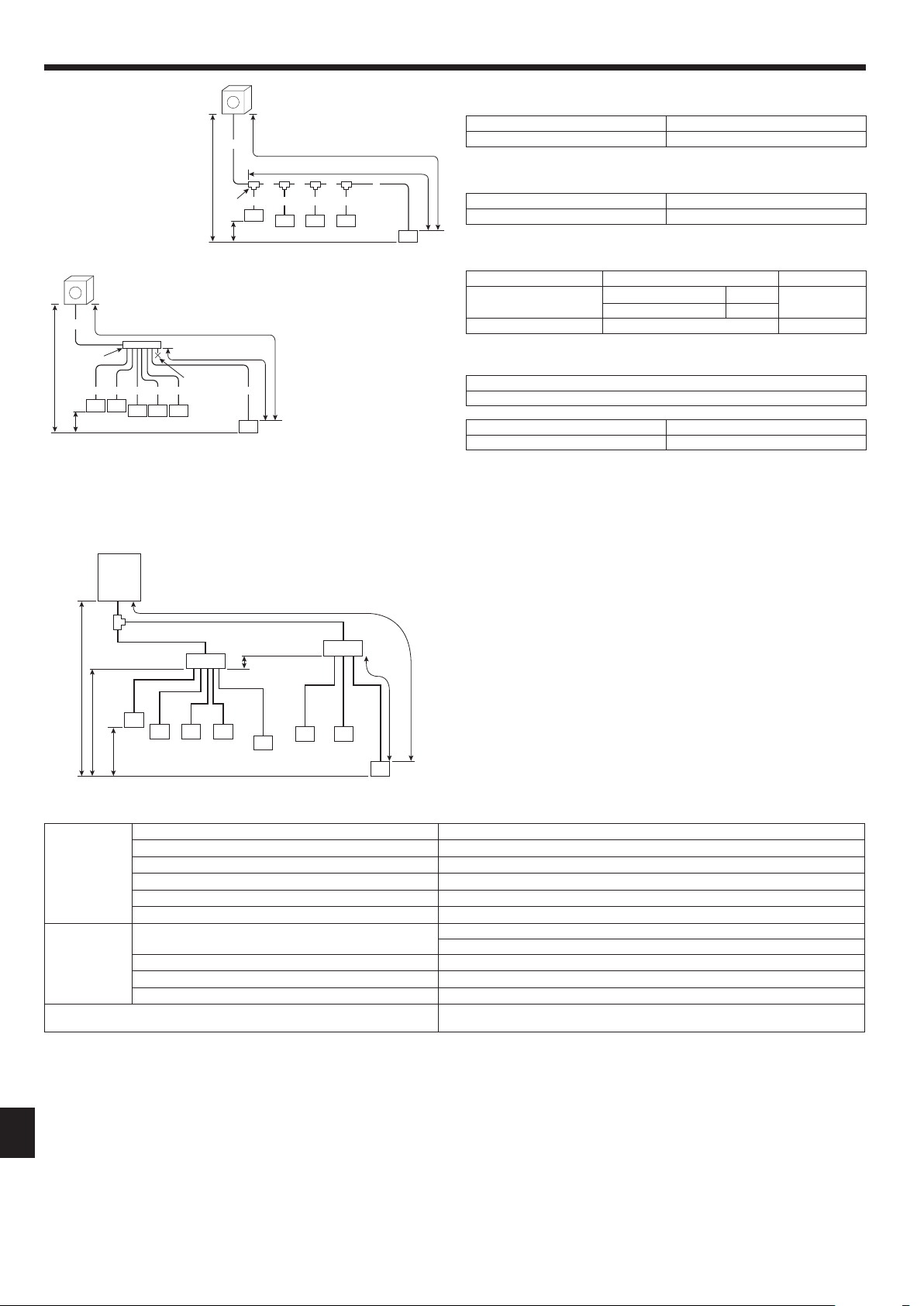
6.2. Controlboxandconnectingpositionofwiring
(Fig.6-1)
1. Connect the indoor unit transmission line to transmission terminal block (TB3), or
connect the wiring between outdoor units or the wiring with the centralized control
system to the centralized control terminal block (TB7).
When using shielded wiring, connect shield ground of the indoor unit transmission
line to the screw (F) and connect shield ground of the line between outdoor units
and the centralized control system transmission line to the shield (S) terminal of
the centralized control terminal block (TB7). In addition, in the case of outdoor
unitswhosepowersupplyconnectorCN41hasbeenreplacedbyCN40,theshield
terminal (S) of terminal block (TB7) of the centralized control system should also
be connected to the screw (F) using attached lead wire.
2. Conduit mounting plates(ø27)are being provided.Passthe power supplyand
transmission wires through the appropriate knock-out holes, then remove the
knock-out piece from the bottom of the terminal block and connect the wires.
3. Fix power source wiring to the terminal block by using buffer bushing for tensile
force (PG connection or the like).
4. The terminal block (TB1B) is for supplying power to the branch box (220
– 240
VAC. max 6 A).
5. The terminal block (TBD1) is for the input of the DRED signals (12 VDC, 1 mA).
Caution:
Neverconnectthetransmissionlinefortheindoorunitorthecentralizedcontrol
systemtransmissionlinetothisterminalblock(TB1B/TBD1).Ifthetransmission
linesareconnected,theindoorunitorcentralizedcontrolcouldbedamaged.
Fig.6-1
<PUMY-SP·VKMD>
M1
S
M2 M1
S
M2
TB3 TB7
B1 B2
TB1B
C
B
E
F
D
L1
L2 L3
N
TB1
A
G
TBD1
1 2
3
C
<PUMY-SP·YKMD>
E Ground for the terminal block (TB3)
F Screw on the electrical component box
G DRED signal input
6.1. Caution
1 Follow ordinance of your governmental organization for technical standard related
to electrical equipment, wiring regulations and guidance of each electric power
company.
2 Wiring for control (hereinafter referred to as transmission line) shall be (5 cm or
more)apartfrompowersourcewiringsothatitisnotinuencedbyelectricnoise
from power source wiring. (Do not insert transmission line and power source wire
in the same conduit.)
3 Be sure to provide designated grounding work to outdoor unit.
4 Give some allowance to wiring for electrical part box of indoor and outdoor units,
because the box is sometimes removed at the time of service work.
5 Neverconnectthemainpowersourcetoterminalblockoftransmissionline.If
connected, electrical parts will be burnt out.
6 Use2-core shield cablefortransmission line.Iftransmission lines ofdifferent
systems are wired with the same multiplecore cable, the resultant poor transmit-
ting and receiving will cause erroneous operations.
7 Onlythetransmissionlinespeciedshouldbeconnectedtotheterminalblockfor
outdoor unit transmission.
(Transmission line to be connected with indoor unit : Terminal block TB3 for
transmission line, Other : Terminal block TB7 for centralized control)
Erroneous connection does not allow the system to operate.
8 In case to connect with the upper class controller or to conduct group operation in
different refrigerant systems, the control line for transmission is required between
the outdoor units each other.
Connect this control line between the terminal blocks for centralized control. (2-
wire line with no polarity)
When conducting group operation in different refrigerant systems without connect-
ing to the upper class controller, replace the insertion of the short circuit connector
fromCN41ofoneoutdoorunittoCN40.
9 Group is set by operating the remote controller.
0 WhenconnectingtheCONNECTIONKIT(PAC-LV11M-J)andanM-seriesindoor
unit,refertotheinstallationmanualfortheCONNECTIONKIT.
1 When connecting a branch box, be sure to turn on the indoor units and the branch
box before turning on the outdoor unit.
2 Usethestrapontheunittosufcientlyfastenthecablesconnectedtothetermi-
nal blocks. In addition, make sure that the fastened cables and the strap do not
interfere with the panels.
RG79Y960H01.indb 15 2018/02/09 14:31:09
16
GB
Exampleofagroupoperationsystemwithmultipleoutdoorunits(Shieldingwiresandaddresssettingarenecessary.)
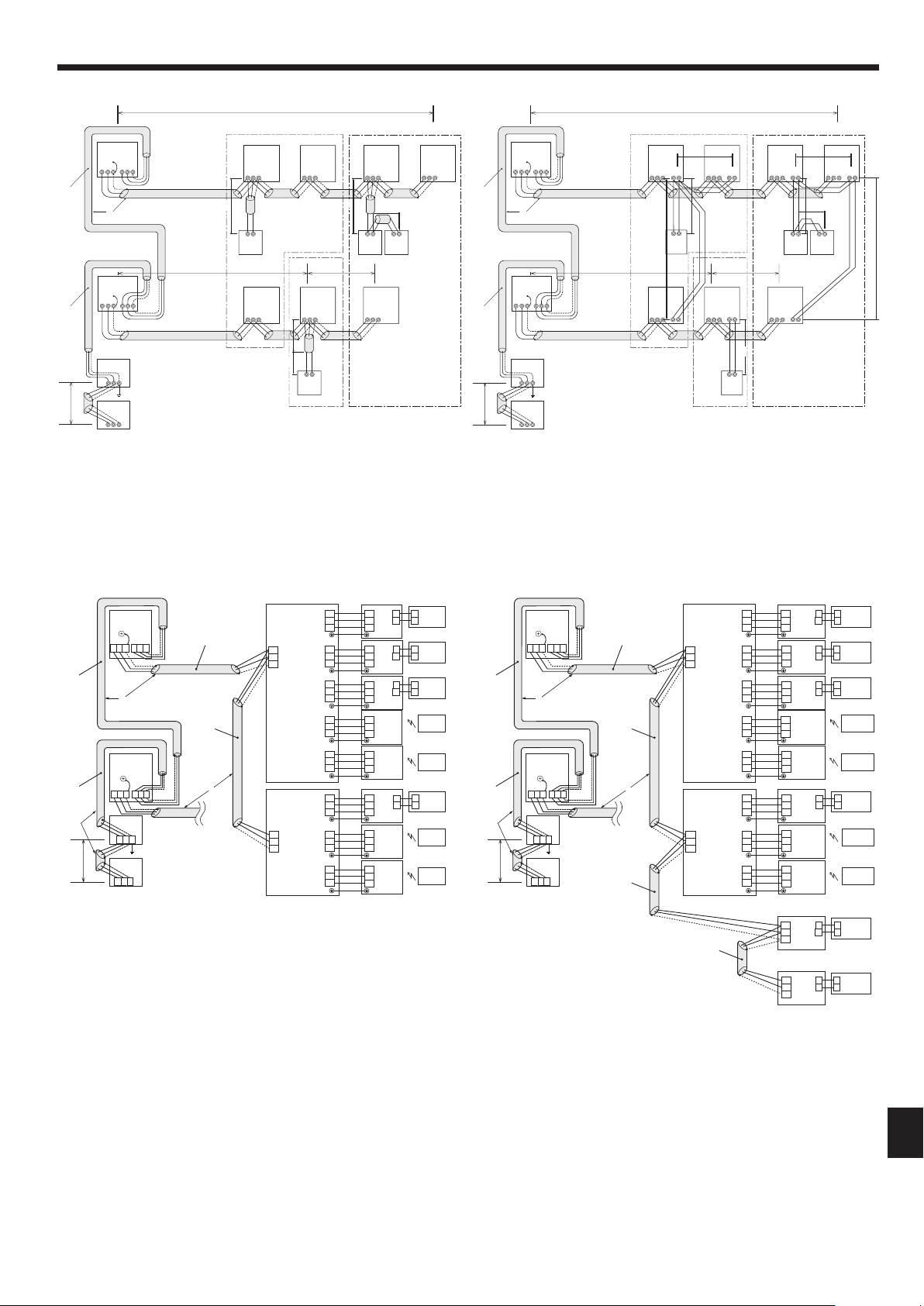
<ExamplesofTransmissionCableWiring>
■ RefertoFig.6-6fromFig.6-2.
<WiringMethodandAddressSettings>
a. Always use shielded wire when making connections between the outdoor unit (OC) and the indoor unit (IC), as well for all OC-OC, and IC-IC wiring intervals.
b. UsefeedwiringtoconnectterminalsM1andM2andthegroundterminalonthetransmissioncableterminalblock(TB3)ofeachoutdoorunit(OC)toterminalsM1,M2
and terminal S on the transmission cable block of the indoor unit (IC).
c. Connect terminals 1 (M1) and 2 (M2) on the transmission cable terminal block of the indoor unit (IC) that has the most recent address within the same group to the terminal
block on the remote controller (RC).
d. Connect together terminals M1, M2 and terminal S on the terminal block for centralized control (TB7) for the outdoor unit (OC).
e. ThejumperconnectorCN41onthecontrolpaneldoesnotchange.
f.
Connect shield ground of the indoor units transmission line to the shield (S) terminal of (TB3) and also connect (S) terminal to the screw (E or F) using attached lead wire.
Connect shield ground of the line between outdoor units and the centralized control system transmission line to the shield (S) terminal of (TB7).
g. Set the address setting switch as follows.
Unit Range Setting Method
M-IC (Main) 01 to 50 Usethemostrecentaddresswithinthesamegroupofindoorunits
M-IC (Sub) 01 to 50
Useanaddress,otherthanthatoftheIC(Main)fromamongtheunitswithinthesamegroupofindoorunits.Thismustbe
in sequence with the IC (Main)
Outdoor unit 51 to 100
Usethemostrecentaddressofalltheindoorunitsplus50
* The address automatically becomes “100” if it is set as “01 - 50”.
M-NETRC(Main)*1 101 to 150 Set at an IC (Main) address within the same group plus 100
M-NETRC(Sub)*1 151 to 200 Set at an IC (Main) address within the same group plus 150
MA RC — Unnecessaryaddresssetting(Necessarymain/subsetting)
*1 An ME remote controller cannot be connected to a system that contains a branch box.
h. Thegroupsettingoperationsamongthemultipleindoorunitsisdonebytheremotecontroller(M-NETRC)aftertheelectricalpowerhasbeenturnedon.
<PermissibleLengths>
1
M-NETRemotecontroller
• Maxlengthviaoutdoorunits:L
1
+L
2
+L
3
+L
4
and L
1
+L
2
+L
3
+L
5
and L
1
+L
2
+L
6
+L
7
[
500 m (1.25 mm² or more)
• Maxtransmissioncablelength:L
1
and L
3
+L
4
and L
3
+L
5
and L
2
+L
6
and L
7
[
200 m (1.25 mm² or more)
• Remotecontrollercablelength:
r
1
,
r
2
,
r
2
+
r
3
,
r
4
[
10 m (0.5 to 1.25 mm²)
If the length exceeds 10 m, use a 1.25 mm² shielded wire. The length of this section (L
8
) should be included in the calculation of the
maximum length and overall length.
2
MARemotecontroller
• Maxlengthviaoutdoorunit(M-NETcable):L
1
+L
2
+L
3
+L
4
and L
1
+L
2
+L
6
+L
7
[
500 m (1.25 mm² or more)
• Maxtransmissioncablelength(M-NETcable):L
1
and L
3
+L
4
and L
2
+L
6
and L
7
[
200 m (1.25 mm² or more)
• Remotecontrollercablelength:
c
1
and
c
1
+
c
2
+
c
3
and
c
1
+
c
2
+
c
3
+
c
4
[
200 m (0.3 to 1.25 mm²)
6. Electricalwork
6.3. Wiringtransmissioncables
1 Typesofcontrolcables
1. Wiring transmission cables
• Typesoftransmissioncables:ShieldingwireCVVS,CPEVSorMVVS
• Cablediameter:Morethan1.25mm
2
• Maximumwiringlength:Within200m
2. M-NETRemotecontrolcables
Kind of remote control cable Shielding wire CVVS, CPEVS or MVVS
Cable diameter 0.5 to 1.25 mm
2
(0.75 to 1.25 mm
2
)*
Remarks
When 10 m is exceeded, use cable with the same
specicationsastransmissionlinewiringcables.
* Connected with simple remote controller.
3. MA Remote control cables
Kind of remote control cable Sheathed 2-core cable (unshielded) CVV
Cable diameter 0.3 to 1.25 mm
2
(0.75 to 1.25 mm
2
)*
Remarks Within 200 m
* Connected with simple remote controller.
2 Wiringexamples
• Controllername,symbolandallowablenumberofcontrollers.
Name Symbol Allowable number of controllers
Outdoor unit controller OC –
Indoor unit controller
M-IC
PUMY-SP112 1 to 9 units per 1 OC *1
PUMY-SP125 1 to 10 units per 1 OC *1
PUMY-SP140 1 to 12 units per 1 OC *1
A-IC
PUMY-SP112
2 to 8 units per 1 OC *1PUMY-SP125
PUMY-SP140
Branch box – – 0 to 2 units per 1 OC
Remote controller RC
M-NETRC*2,*3
Maximum of 12 control-
lers for 1 OC (Can not be
connected if Branch box
is used.)
MA-RC Maximum of 2 per group
Note:
*1. Thenumberofconnectableunitsmaybelimitedbysomeconditionssuch
asanindoorunit’scapacityoreachunit’sequivalentpowerconsumption.
*2. Don’tusetheLossnaycontroller(PZ-61DR-E,PZ-43SMF-E,PZ-52SF-E,
PZ-60DR-E).
*3. AnMEremotecontrollercannotbeconnectedtoasystemthatcontains
abranchbox.
RG79Y960H01.indb 16 2018/02/09 14:31:09
17
GB
6. Electricalwork
Fig.6-4 Fig.6-5
TB7
TB3
(51)
L
3
L1
OC
TB7
(53)
OC
L
4
L5
M1 M2
S
M1 M2
S
S
M1 M2
S
TB3
M1 M2
S
M1 M2
S
M1 M2
TB3A
A-IC
(01)
A-IC
(02)
A-IC
(03)
A-IC
(04)
A-IC
MA-RC
MA-RC
MA-RC
MA-RC
WL-RC
WL-RC
WL-RC
WL-RC
(05)
A-IC
(06)
A-IC
(07)
A-IC
(08)
S1
S2
S3
TB3A
S1
S2
TB15
1
2
A
B
A
B
A
B
A
B
TB15
1
2
TB15
1
2
TB15
1
2
S3
TB3A
S1
S2
S3
TB3A
S1
S2
S3
TB3A
S1
S2
S3
TB3A
S1
S2
S3
TB3A
S1
S2
S3
TB3A
S1
S2
S3
TB3A
S1
S2
S3
TB3B
S1
S2
S3
TB3C
S1
S2
S3
TB3D
S1
S2
S3
TB3E
S1
S2
S3
TB3A
S1
S2
S3
TB3B
S1
S2
S3
TB3C
S1
S2
S3
M1
M2
S
TB5
M1
M2
S
TB5
L
(01)
(06)
2
A
A
A
TB7
TB3
(51)
L
5
L1
OC
TB7
(53)
OC
L
6
L7
M1 M2
S
M1 M2
S
S
M1 M2
S
TB3
M1 M2
S
M1 M2
S
M1 M2
TB3A
A-IC
(01)
A-IC
(02)
A-IC
(03)
A-IC
(04)
A-IC
MA-RC
MA-RC
MA-RC
MA-RC
WL-RC
WL-RC
WL-RC
WL-RC
(05)
A-IC
(06)
A-IC
(07)
A-IC
(08)
S1
S2
S3
TB3A
S1
S2
TB15
1
2
A
B
A
B
A
B
A
B
TB15
1
2
TB15
1
2
TB15
1
2
S3
TB3A
S1
S2
S3
TB3A
S1
S2
S3
TB3A
S1
S2
S3
TB3A
S1
S2
S3
TB3A
S1
S2
S3
TB3A
S1
S2
S3
TB3A
S1
S2
S3
TB3B
S1
S2
S3
TB3C
S1
S2
S3
TB3D
S1
S2
S3
TB3E
S1
S2
S3
TB3A
S1
S2
S3
TB3B
S1
S2
S3
TB3C
S1
S2
S3
M1
M2
S
TB5
M1
M2
S
TB5
L
2
A
A
A
M-IC
(09)
M-IC
(10)
MA-RC
MA-RC
TB5
M1
M2
TB15
1
2
A
B
A
B
TB15
1
2
S
TB5
M1
M2
S
L3
L4
<ExampleofTransmissionCableWiring:Mixingsystem><ExampleofTransmissionCableWiring:ConnectingwithBranchbox>
<Permissiblelength>
Longestlengthviaoutdoorunits:
L
1
+L
2
+L
3
+L
4
+L
5
+L
6
+L
7
{
500m(1640ft.)
(1.25mm
2
ormore)
Longesttransmissioncablelength:
L
1
+L
2
+L
3
+L
4
, L
5
+L
6
, L
7
{
200m(656ft.)(1.25mm
2
ormore)
Power
Supply
Unit
System
controller
Branch Box
Branch Box
Branch Box
Branch Box
<PermissibleLengths>
Maxlengthviaoutdoorunits(M-NETcable):
L
1
+L
2
+L
3
+L
4
+L
5
{
500m(1.25mm
2
ormore)
Maxtransmissioncablelength(M-NETcable):
L
1
+L
2
, L
3
+L
4
, L
5
{
200m(1.25mm
2
ormore)
(01)
(06)
■
M-NETRemoteController
■
MARemoteController
A
B
C
E
M-IC
S 2M 1M
TB5
M-NET RC
(01)
M-IC
S 2M 1M
TB5
(03)
M-IC
S 2M 1M
TB5
(02)
M-IC
M1 M2 S
TB5
(04)
M-IC
S 2M 1M
TB5
(05)
M-IC
S 2M 1M
TB5
(07)
M-IC
S 2M 1M
TB5
(06)
L1
(101)
M-NET RC
(105)
(104)
M-NET RC
(155)
L3 L4
L5
A B A B A B
A B
A
B
C
E
M-IC
S 21 2M 1M
TB5 TB15
1 2
TB15
1 2
TB15
1 2
TB15
1 2
TB15
1 2
TB15
1 2
TB15
MA-RC
(01)
M-IC
S 2M 1M
TB5
(03)
M-IC
M1 M2 S
TB5
(02)
M-IC
M1 M2 S
TB5
(04)
M-IC
M1 M2 S
TB5
(05)
M-IC
M1 M2 S
TB5
(07)
M-IC
M1 M2 S
TB5
(06)
L1
m
1
m 4
m 3
L3 L4
m
3
A B
A B
A B
m 1
m 1
m 2 m 2
A B
M-NET RC
MA-RC
MA-RC
MA-RC
R2
R3
R1
R4
S
Power Supply
Unit
S
L7
M1M2
M1M2
M1M2S
Power Supply
Unit
M1M2S
G-50A
L
7
D
M1M2S
TB7
M1M2S
TB3
(51)
OC
L2
L6
M1M2SM1M2S
TB3
(53)
OC
TB7
D
M1M2S
TB7
M1M2S
TB3
(51)
OC
L2
L6
M1M2SM1M2S
TB3
(53)
OC
TB7
Fig.6-3Fig.6-2
A
: Group 1
B
: Group 2
C
: Group 3
D
: Shielded Wire
E
: Sub Remote Controller
( ): Address
A
: Shielded wire
( ) : Address example
A
: Shielded wire
( ) : Address example
Power
Supply
Unit
System
controller
System
controller
RG79Y960H01.indb 17 2018/02/09 14:31:09
18
GB
6. Electricalwork
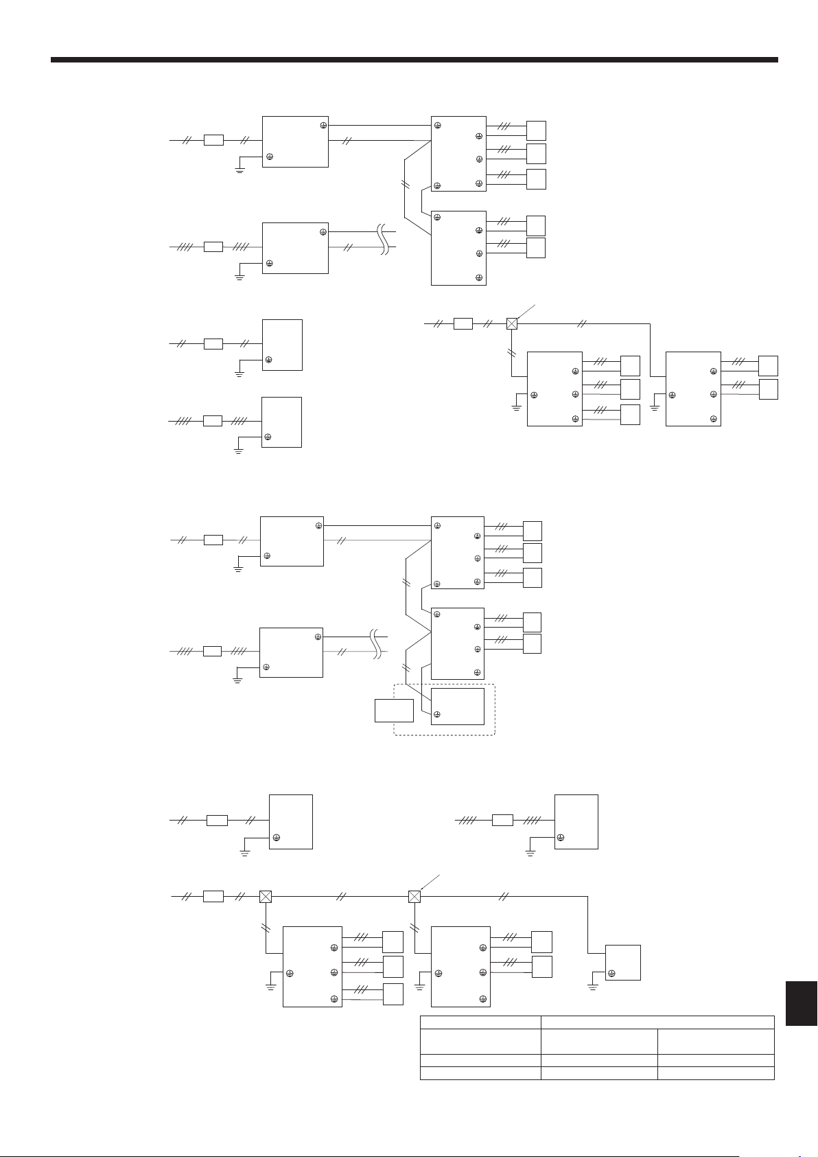
6.4. Wiringofmainpowersupplyandequipmentcapacity
SchematicDrawingofWiring(Example)(Fig.6-7)
A
B
D D
F
A
D D
Fig.6-7
Fig.6-6
3N~380-400-415V50Hz
3N~380V60Hz
~/N220-230-240V50Hz
~/N220V60Hz
OC
BC
ABCDE
A-IC A-ICA-ICA-IC
WL-RCWL-RCWL-RC
A-ICA-ICA-IC
WL-RCWL-RCWL-RC
A-IC
MA-RC MA-RC
BC
MA-RC
M-IC
ABC
MA-RC
M-IC
(5-branch type) (3-branch type)
OC: Outdoor unit
BC: Branch box
M-IC:M-NetcontrolIndoorunit(CityMultiindoorunit)
A-IC: A-control indoor unit (M, P, S series indoor unit)
MA-RC: MA remote controller
M-NETRC:M-NETremotecontroller
WL-RC: Wireless remote controller
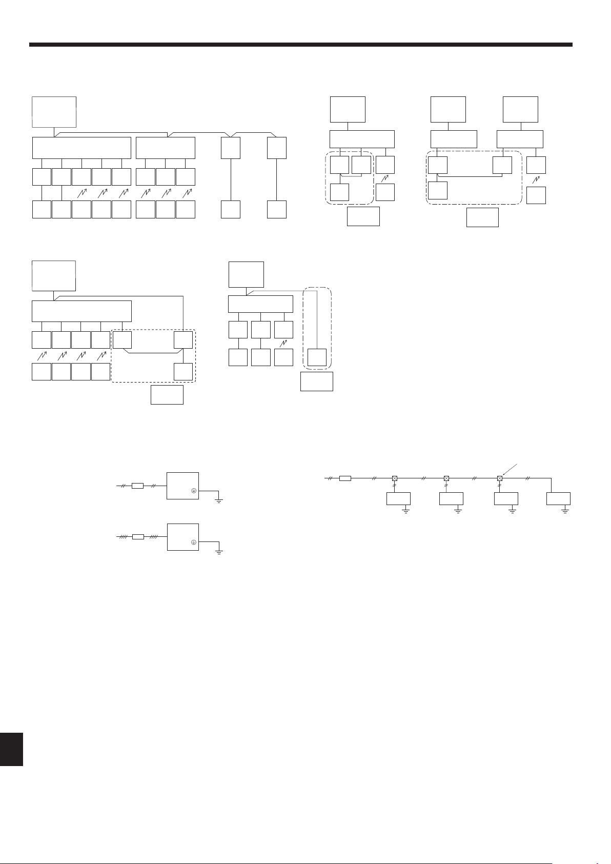
[2]Incorrectsystems
Systemchart<mixedsystemwithbranchboxesandCityMultiindoorunits>
[1]Basicsystem
1
Group operation by MA
remote controller
1
Plural indoor units cannot be operated by a MA remote
controller.
2
Different refrigerant systems cannot be connected together.
3
Differenttypescontrolsystems(A-IC/M-IC)cannotbecon-
nected together.
4
AnM-NETremotecontrollercannotbeconnectedtoa
system that contains a branch box.
CO
BC
A B
C
NO
A-ICA-ICA-IC
MA-RC WL-RC
(3-branch type)
2
Group operation between different
refrigerant systems
COCO
BC
A B C
BC
A B C
NO
A-IC A-IC A-IC
MA-RC
WL-RC
(3-branch type)
(3-branch type)
OC
BC
ABCDE
A-IC A-ICA-ICA-IC
WL-RCWL-RCWL-RCWL-RC
M-IC
MA-RC
A-IC
NO
(5-branch type)
3
Group operation between A-control system and M-
NETcontrolsystem
4
ME remote controller connection to a system that
contains a branch box
CO
BC
A B
C
A-ICA-ICA-IC
MA-RC MA-RC
NO
M-NET
RC
WL-RC
(3-branch type)
■
PUMY-SP·VKMD
■
PUMY-SP·YKMD
~/N220-230-240V50Hz
~/N220V60Hz
A
B
A
Switch (Breakers for Wiring and Current Leakage)
B
OutdoorUnit
C
Branch box
D
A-control indoor unit (M, P, S series indoor unit)
E
M-NetcontrolIndoorunit(CityMultiindoorunit)
F
Pull Box
RG79Y960H01.indb 18 2018/02/09 14:31:09
19
GB
6. Electricalwork
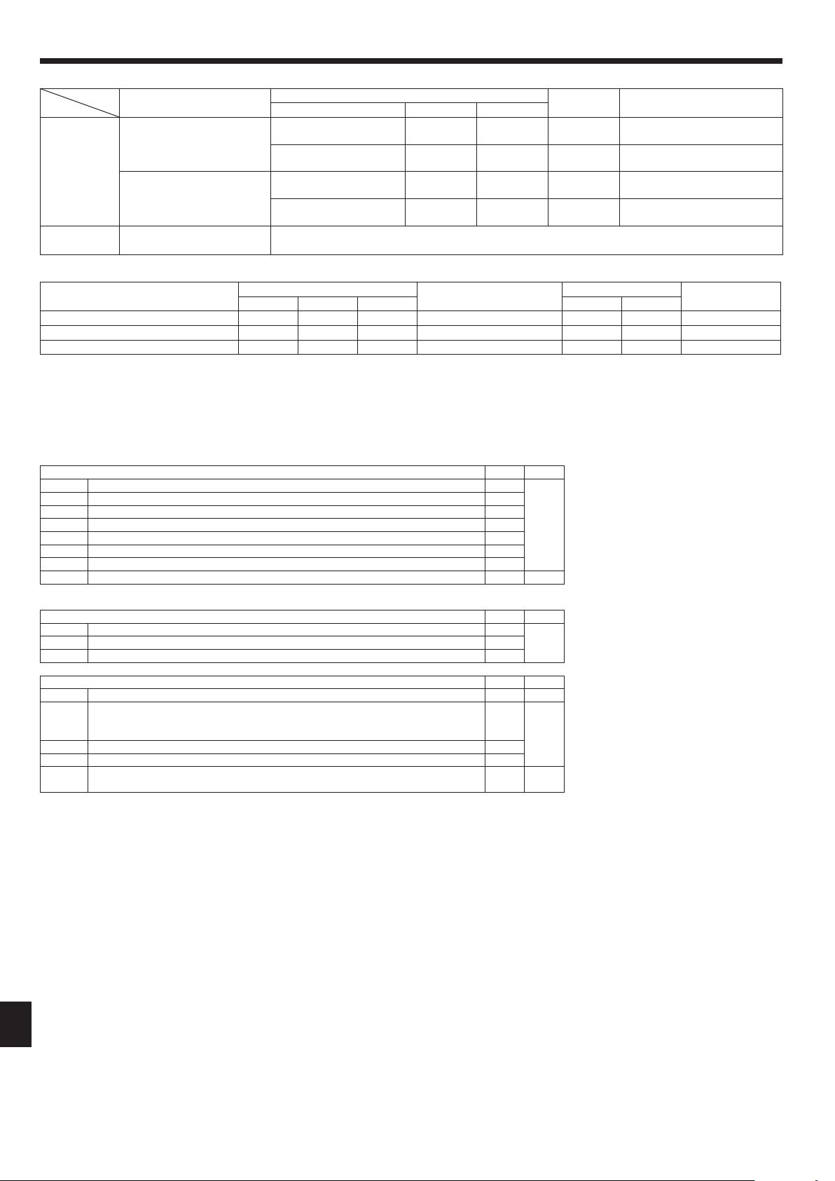
Note:ReactorBOX(Optionalparts)forBranchbox.
Whentheproductisusedforapurposeotherthanasprofessionalequipment,
theReactorBOXmaybenecessary.
Branch box power supply method
Outdoor unit
Power supply from
outdoor unit
Separate power supply
1-phase power supply Unnecessary Necessary
3-phase power supply Necessary Necessary
SchematicDrawingofWiring:Mixingsystem(Fig.6-9)
<Whenpowerissuppliedfromtheoutdoorunit>
<Whenpowerissuppliedseparately>
*TheM-NETControlIndoorunitcannotreceivepowersuppliedfromanoutdoorunit,soprovideitwithpowerseparately.
L/N L/N
S1/S2/S3
S1/S2/S3
S1/S2/S3
L/N
S1/S2/S3
S1/S2/S3
S1/S2/S3
D
E
C
D
D
D
C
D
A
F
~/N220-230-240V50Hz
~/N220V60Hz
L1/L2/L3/N
A
B
3N~380-400-415V50Hz
3N~380V60Hz
Fig.6-9
■
PUMY-SP·VKMD
~/N220-230-240V50Hz
~/N220V60Hz
■
PUMY-SP·YKMD
3N~380-400-415V50Hz
3N~380V60Hz
■
PUMY-SP·VKMD
■
PUMY-SP·YKMD
~/N220-230-240V50Hz
~/N220V60Hz
B1/B2
S1/S2/S3
S1/S2/S3
S1/S2/S3
L/N
L/N
S1/S2/S3
S1/S2/S3
S1/S2/S3
L/N
L/N
D
D
D
D
D
C
C
B
A
E
NO
L1/L2/L3/N
B
A
L/N
A
B
SchematicDrawingofWiringConnectionwithBranchBox(Example)(Fig.6-8)
<Whenpowerissuppliedfromtheoutdoorunit>
Fig.6-8
<Whenpowerissuppliedseparately>
~/N220-230-240V50Hz
~/N220V60Hz
L/N
S1/S2/S3
S1/S2/S3
S1/S2/S3
L/N
S1/S2/S3
S1/S2/S3
S1/S2/S3
D
C
D
D
D
C
D
A
F
S1/S2/S3
S1/S2/S3
S1/S2/S3
L/N
L/N
S1/S2/S3
S1/S2/S3
S1/S2/S3
D
D
D
D
D
C
C
B1/B2
L/N
B
A
L1/L2/L3/N
A
B
3N~380-400-415V50Hz
3N~380V60Hz
■
PUMY-SP·VKMD
~/N220-230-240V50Hz
~/N220V60Hz
■
PUMY-SP·YKMD
■
PUMY-SP·YKMD
3N~380-400-415V50Hz
3N~380V60Hz
L1/L2/L3/N
B
A
L/N
A
B
■
PUMY-SP·VKMD
~/N220-230-240V50Hz
~/N220V60Hz
RG79Y960H01.indb 19 2018/02/09 14:31:10
20
GB
6. Electricalwork
ThicknessofWireforMainPowerSupplyandOn/OffCapacities
Model
Power supply
Minimum Wire Thickness (mm²)
Breaker for
Wiring *1
Breaker for Current Leakage
Main Cable Ground
Outdoor unit
~/N220-230-240V50Hz
~/N220V60Hz
When power is supplied
separately
6.0 6.0
32 A 32 A 30 mA 0.1 sec. or less
When power is supplied from
the outdoor unit
6.0 6.0
40 A 40 A 30 mA 0.1 sec. or less
3N~380-400-415V50Hz
3N~380V60Hz
When power is supplied
separately
2.5 2.5
16 A 16 A 30 mA 0.1 sec. or less
When power is supplied from
the outdoor unit
4.0 4.0
25 A 25 A 30 mA 0.1 sec. or less
Indoorunit/
Branch box
~/N220-230-240V50Hz
~/N220V60Hz
Refer to the following indoor unit or branch box wiring and breaker capacity calculation.
*1.Abreakerwithatleast3.0mmcontactseparationineachpolesshallbeprovided.Useearthleakagebreaker(NV).
Total operating current of the indoor unit
Minimum wire thickness (mm²)
Ground-fault interrupter *1
Local switch (A)
Breaker for wiring
(NFB)
Main Cable Branch Ground
Capacity Fuse
F0 = 16 A or less *2
1.5 1.5 1.5
20 A current sensitivity *3 16 16 20
F0 = 25 A or less *2
2.5 2.5 2.5
30 A current sensitivity *3 25 25 30
F0 = 32 A or less *2
4.0 4.0 4.0
40 A current sensitivity *3 32 32 40
Apply to IEC61000-3-3 about max. permissive system impedance.
*1 The Ground-fault interrupter should support inverter circuit.
The Ground-fault interrupter should combine using of local switch or wiring breaker.
*2 Please take the larger of F1 or F2 as the value for F0.
F1 = Total operating maximum current of the indoor units × 1.2
F2={V1×(QuantityofType1)/C}+{V1×(QuantityofType2)/C}+···+{V1×(QuantityofType16)/C}
Connect to Branch box (PAC-MK·BC)
Indoor unit V1 V2
Type 1 PEAD-RP·JAA 26.9
2.4
Type 2 SEZ-KD·VA(L), PLA-RP·BA, PCA-RP·KAQ 19.8
Type 3 SLZ-KF·VA3 17.1
Type 4 MLZ-KP·VF-A 9.9
Type 5 MFZ-KJ·VE-A1,MSZ-AP·VGD-A1 7.4
Type 6 MSZ-GE·VAD-A1, MSZ-FH·VE-A1, MSZ-EF·VE2-A1 6.8
Type 7 SLZ-KA·VA(L) 3.5
Type 8 Branch box (PAC-MK·BC) 5.1 3.0
Connect to Connection kit (PAC-LV11M)
Indoor unit V1 V2
Type 9 MSZ-AP·VGD 7.4
2.4Type 10 MSZ-GE·VAD, MSZ-EF·VE2, MSZ-FH·VE 6.8
Type 11 Connection kit (PAC-LV11M) 3.5
Indoor unit V1 V2
Type 12 PEFY-P·VMA(L)-E, PEFY-P·VMA3-E 38.0 1.6
Type 13
PMFY-P·VBM-E, PLFY-P·VBM-E, PLFY-P·VFM-E1, PEFY-P·VMS1(L)-E,
PCFY-P·VKM-E, PKFY-P·VHM-E, PKFY-P·VKM-E, PFFY-P·VKM-E2,
PFFY-P·VLRM(M)-E
19.8
2.4
Type 14 PLFY-P·VCM-E2 9.9
Type 15 PKFY-P·VBM-E 3.5
Type 16
PLFY-P·VLMD-E,PEFY-P·VMH(S)-E,PEFY-P·VMR-E-L/R,
PEFY-P·VMH-E-F, PFFY-P·VLEM-E
0 0
C : Multiple of tripping current at tripping time 0.01s
Please pick up “C” from the tripping characteristic of the breaker.
RG79Y960H01.indb 20 2018/02/09 14:31:10
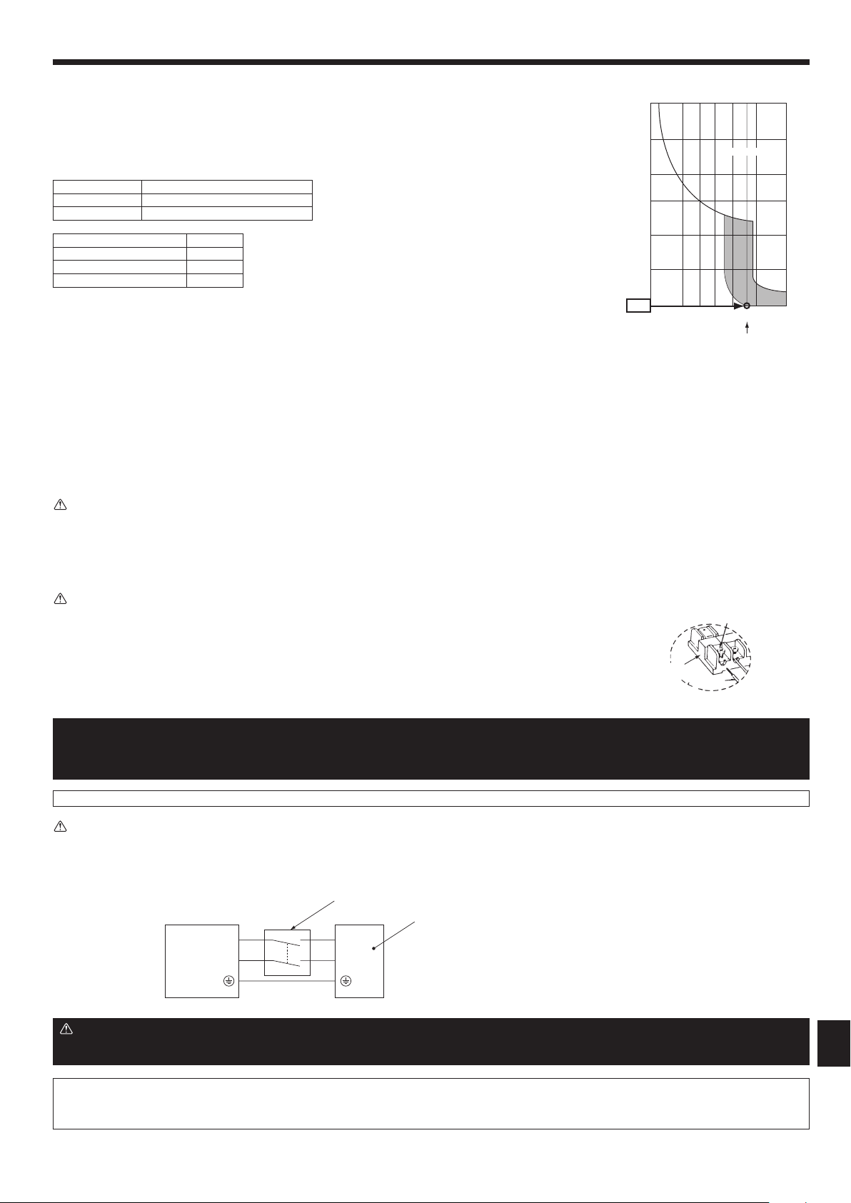
21
GB
1. Useaseparatepowersupplyfortheoutdoorunitandindoorunit.
2. Bearinmindambientconditions(ambienttemperature,directsunlight,rainwater,etc.)whenproceedingwiththewiringandconnections.
3. Thewiresizeistheminimumvalueformetalconduitwiring.Thepowercordsizeshouldbe1rankthickerconsiderationofvoltagedrops.
Makesurethepower-supplyvoltagedoesnotdropmorethan10%.
4. Specicwiringrequirementsshouldadheretothewiringregulationsoftheregion.
5. Powersupplycordsofpartsofappliancesforoutdooruseshallnotbelighterthanpolychloroprenesheathedexiblecord(design60245IEC57).Forexample,
usewiringsuchasYZW.
6. Installanearthlongerthanothercables.
Sample chart
6. Electricalwork
Warning:
• Please turn off the main power supply when servicing.And do not touch the B1, B2 terminals when the power is energized. If isolator should be used
betweenoutdoorunitandbranchbox/indoorunitandbranchbox,pleaseuse2-poletype.
(Pleaserefertogurebelow.)
Caution:
Afterusingtheisolator,besuretoturnoffandonthemainpowersupplytoresetthesystem.Otherwise,theoutdoorunitmaynotbeabletodetectthebranch
box(es)orindoorunits.
Besuretoconnecttheoutdoor-branchbox/indoor-branchboxconnectingcablesdirectlytotheunits(nointermediateconnections).
Intermediateconnectionscanlead to communication errors if water entersthecablesandcauses insufcient insulation to ground or a poorelectricalcontactat the
intermediate connection point.
(If an intermediate connection is necessary, be sure to take measures to prevent water from entering the cables.)
B1
B2
L
N
Outdoor unit
2 poles isolator (Switch)
Branch box
Warning:
• Besuretousespeciedwirestoconnectsothatnoexternalforceisimpartedtoterminalconnections.Ifconnectionsarenotxedrmly,itmaycauseheat-
ingorre.
• Besuretousetheappropriatetypeofovercurrentprotectionswitch.Notethatgeneratedovercurrentmayincludesomeamountofdirectcurrent.
• Besuretoattachtheterminalblockcovers/paneloftheoutdoorunitsecurely.
Ifitisnotattachedcorrectly,ifcouldresultinareoranelectricshockduetodust,water.etc.
Caution:
• Becarefulnottomakemis-wiring.
• Firmlytightentheterminalscrewstopreventthemfromloosening.
• Aftertightening,pullthewireslightlytoconrmthattheynotmove.
• Iftheconnectingwireisincorrectlyconnectedtotheterminalblock,theunitdoesnotoperatenormally.
• Someinstallationsitemayrequireattachmentofanearthleakagebreaker.Ifnoearthleakagebreakerisinstalled,itmay
causeanelectricshock.
• Donotuseanythingotherthanbreakerandfusewithcorrectcapacity.Usingfuseandwireorcopperwirewithtoolarge
capacitymaycauseamalfunctionofunitorre.
IMPORTANT
Makesurethatthecurrentleakagebreakerisonecompatiblewithhigherharmonics.
Alwaysuseacurrentleakagebreakerthatiscompatiblewithhigherharmonicsasthisunitisequippedwithaninverter.
Theuseofaninadequatebreakercancausetheincorrectoperationofinverter.
Neversplicethepowercableortheindoor-outdoor-branchboxconnectioncable,otherwiseitmayresultinasmoke,areorcommunicationfailure.
<Exampleof“F2”calculation>
Condition PEFY-VMS1 × 4 + PEFY-VMA × 1, C = 8 (refer to right sample chart)
F2=19.8×4/8+38×1/8
= 14.65
*3 Current sensitivity is calculated using the following formula.
G1={V2×(QuantityofType1)}+{V2×(QuantityofType2)}+···+{V2×(QuantityofType16)}
+{V3×(Wirelength[km])}
G1 Current sensitivity
30 or less 30 mA 0.1 sec or less
100 or less 100 mA 0.1 sec or less
Wire thickness V3
1.5 mm
2
48
2.5 mm
2
56
4.0 mm
2
66
6000
600
60
10
1
1 2 3 4 6 8
C
10 20
Rated Tripping current (x)
SAMPLE
0.1
0.01
TrippingTime[s]
Connection details
Lead wire
Terminal
block
Loosen terminal screw.
RG79Y960H01.indb 21 2018/02/09 14:31:10
22
GB
6. Electricalwork
6.5.Addresssetting
Switch address setting
Outdoor
Branch Box
M, S, P
Series
Indoor
CITYMULTI
Series Indoor
Address Connection Setting
Switch
tens digit ones digit tens digit ones digit
A B C D E –
1 2 3 4 5 6
ON: Indoorconnect
OFF: Noconnection
(SW1-6 not use)
None
tens digit ones digit
SWU2 SWU1 SW12 SW11 SW1 SW12 SW11
Range 51 - 100 1 - 50 – – 1 - 50
Setting
M-Control
Indoor or
Branch Box
address +50
• Accordingtothesetaddress(forexample,01),the
addresses for the connected indoor units are set
sequentially (for example, 02, 03, 04, and 05).
• Specifywhetherindoorunitsareconnectedto
each port (A, B, C, D, and E).
There are
no address
settings for
the indoor
units.
–
SW1 1 2 3 4 5
ON ON ON ON ON
Port A B C D E
Address
01 (SW11, 12)
02 03 04 05 (sequential numbers)
SW1 1 2 3 4 5 (6)
Port A B C D E not use
IndoorunitsareconnectedON
Indoor units are not connected OFF
Note: 1.Branchboxaddress
Whensettingtheaddress,useanumberwithintherange1–50.
Ex.Thesetaddressis(47)andthereare5indoorunits(A,B,C,D,andE).
IfA:(47),B:(48),C:(49),D:(50),andE:(51),Eisincorrectbecauseitexceeds50.
Ex1.Outdoor+Branch<1>(M,S,PSeriesIndoorA,B,C,D,E)+Branch<2>(M,S,PSeriesIndoorA,B,C)
Outdoor
address
(51) *1
*1 Outdoor address
Branch-Box<1>startaddress+50=01+50=51
*2 Branch-Box<1>
A-port address = Start address = 01
B-port address = Start address + 1 = 02
C-port address = Start address + 2 = 03
D-port address = Start address + 3 = 04
E-port address = Start address + 4 = 05
*3 Branch-Box<2>
Branch-Box<2>startaddress
=Branch-Box<1>oldeststartaddress+1
= 05 + 1 = 06
A-port address = Start address = 06
B-port address = Start address + 1 = 07
C-port address = Start address + 2 = 08
Ex2.Outdoor+Branch<1>(M,S,PSeriesIndoor,C,E)+Branch<2>(M,S,PSeriesIndoorA,C,E)
Outdoor
address
(51) *1
*1 Outdoor address
Branch-Box<1>startaddress+50=01+50=51
*2 Branch-Box<1>
A-port address = Start address = 01
B-port address no connection
C-port address = Start address + 1 = 02
D-port address no connection
E-port address = Start address + 2 = 03
*3 Branch-Box<2>
Branch-Box<2>startaddress
=Branch-Box<1>oldeststartaddress+1
= 03 + 1 = 04
A-port address = Start address = 04
B-port address no connection
C-port address = Start address + 1 = 05
D-port address no connection
E-port address = Start address + 2 = 06
M, S, P Series Indoor
M, S, P Series Indoor
M, S, P Series Indoor
M, S, P Series Indoor
M, S, P Series Indoor
M, S, P Series Indoor
M, S, P Series Indoor
M, S, P Series Indoor
M, S, P Series Indoor
M, S, P Series Indoor
M, S, P Series Indoor
M, S, P Series Indoor
M, S, P Series Indoor
M, S, P Series Indoor
(01) = A-port
(02) = B-port
(03) = C-port
(04) = D-port
(05) = E-port
(06) = A-port
(07) = B-port
(08) = C-port
(01) = A-port
non B-port
(02) = C-port
non D-port
(03) = E-port
(04) = A-port
non B-port
(05) = C-port
non D-port
(06) = E-port
Branch-Box<1>
address (01) *2
SW11,3,5 ON
SW1 2, 4 OFF
Branch-Box<2>
address (04) *3
SW11,3,5 ON
SW1 2, 4 OFF
Branch-Box<2>
address (06) *3
SW11,2,3 ON
SW1 4, 5 OFF
Branch-Box<1>
address (01) *2
SW11,2,3,4,5ON
RG79Y960H01.indb 22 2018/02/09 14:31:10
23
GB
Ex3.Outdoor+Branch<1>(M,S,PSeriesIndoorA,B,C,D,E)+Branch<2>(M,S,PSeriesIndoorA,B,C)+CITYMULTISeriesIndoor<1>+CITYMULTISeriesIndoor<2>
Outdoor
address
(51) *1
*1 Outdoor address
BranchBox<1>startaddress+50=01+50=51
*2 BranchBox<1>
A-port address = Start address = 01
B-port address = Start address + 1 = 02
C-port address = Start address + 2 = 03
D-port address = Start address + 3 = 04
E-port address = Start address + 4 = 05
*3 BranchBox<2>
BranchBox<2>startaddress
=CITYMULTISeriesIndoor<1>address+1
= 06 + 1 = 07
A-port address = Start address = 07
B-port address = Start address + 1 = 08
C-port address = Start address + 2 = 09
M, S, P Series Indoor
M, S, P Series Indoor
M, S, P Series Indoor
M, S, P Series Indoor
M, S, P Series Indoor
M, S, P Series Indoor
M, S, P Series Indoor
M, S, P Series Indoor
(01) = A-port
(02) = B-port
(03) = C-port
(04) = D-port
(05) = E-port
CITYMULTISeriesIndoor<1>
address (06)
CITYMULTISeriesIndoor<2>
address (10)
Branch-Box<1>
address (01) *2
SW11,2,3,4,5ON
(07) = A-port
(08) = B-port
(09) = C-port
Branch-Box<2>
address (07) *3
SW11,2,3 ON
SW1 4, 5 OFF
6. Electricalwork
RG79Y960H01.indb 23 2018/02/09 14:31:10
24
GB
7.2. Testrun
7.2.1. Usingremotecontroller
Refer to the indoor unit installation manual.
• Besuretoperformthetestrunforeachindoorunit.Makesureeachindoor
unit operates properly following the installation manual attached to the unit.
• Ifyouperformthetestrunforallindoorunitsatonce,youcannotdetectany
erroneous connection, if any, of the refrigerant pipes and the connecting wires.
* The compressor operation is not available for 3 minutes at least after the power
is supplied.
• Thecompressorcanemitnoisejustafterturnonthepowersupplyorincase
of low outside air temperature.
Abouttherestartprotectivemechanism
Once the compressor stops, the restart preventive device operates so the compressor
will not operate for 3 minutes to protect the air conditioner.
7.3. Refrigerantcollecting(Pumpdown)
Perform the following procedures to collect the refrigerant when moving the indoor
unit or the outdoor unit.
1 Turn off the circuit breaker.
2 Connect the low pressure side of the gauge manifold to the service port of the
gas side stop valve.
3 Close the liquid stop valve.
4 Supply power (circuit breaker).
* Start-up of the indoor-outdoor communication takes about 3 minutes after the
power (circuit breaker) is turned on. Start the pump-down operation 3 to 4 minutes
afterthepower(circuitbreaker)isturnedON.
5 ConrmthatSW3-2issettoOFF,andthensetSW3-1toONtoperformthetest
run for cooling operation. The compressor (outdoor unit) and ventilators (indoor
and outdoor units) start operating and test run for cooling operation begins.
Immediately after performing the test run for cooling operation, set the outdoor
serviceswitchSW2-4(pumpdownswitch)fromOFFtoON.
* DonotcontinuetooperateforalongtimewiththeswitchSW2-4settoON.Make
sure to switch it to OFF after pump down is completed.
6 Fully close the gas stop valve when the pressure reading on the gauge drops
0.05-0.00MPa(approximately0.5-0.0kgf/cm
2
)
7 Stop the air conditioner operation (SW3-1: OFF). Set the outdoor service switch
SW2-4fromONtoOFF.
8 Turn off the power supply (circuit breaker).
* If too much refrigerant has been added to the air conditioner system, the pres-
suremaynotdropto0.05MPa(0.5kgf/cm
2
). If this occurs, use a refrigerant
collecting device to collect all of the refrigerant in the system, and then recharge
the system with the correct amount of refrigerant after the indoor and outdoor
units have been relocated.
Warning:
Whenpumpingdowntherefrigerant,stopthecompressorbeforedisconnect-
ingtherefrigerantpipes.Thecompressormayburstandcauseinjuryifany
foreignsubstance,suchasair,entersthesystem.
7.1. Beforetestrun
► Aftercompleting installationand thewiringandpipingoftheindoor and
outdoorunits,checkforrefrigerantleakage,loosenessinthepowersupply
orcontrolwiring,wrongpolarity,andnodisconnectionofonephaseinthe
supply.
► Usea500-voltM-ohmtestertocheckthattheresistancebetweenthepower
supplyterminalsandgroundisatleast1MΩ.
► Donotcarryoutthistestonthecontrolwiring(lowvoltagecircuit)terminals.
Warning:
Donotusetheairconditioneriftheinsulationresistanceislessthan1MΩ.
Insulation resistance
After installation or after the power source to the unit has been cut for an extended
period,theinsulationresistancewilldropbelow1MΩduetorefrigerantaccumulat-
ing in the compressor. This is not a malfunction. Perform the following procedures.
1. Remove the wires from the compressor and measure the insulation resistance of
the compressor.
2. Iftheinsulationresistanceisbelow1MΩ,thecompressorisfaultyortheresistance
dropped due the accumulation of refrigerant in the compressor.
3. After connecting the wires to the compressor, the compressor will start to warm
up after power is supplied. After supplying power for the times indicated below,
measure the insulation resistance again.
• Theinsulationresistancedropsduetoaccumulationofrefrigerantinthecom-
pressor.Theresistancewillriseabove1MΩafterthecompressoriswarmed
up for 12 hours.
(The time necessary to warm up the compressor varies according to atmospheric
conditions and refrigerant accumulation.)
• To operatethecompressorwithrefrigerantaccumulatedinthecompressor,the
compressor must be warmed up at least 12 hours to prevent breakdown.
4. Iftheinsulationresistancerisesabove1MΩ,thecompressorisnotfaulty.
Caution:
• Thecompressorwillnotoperateunlessthepowersupplyphaseconnection
iscorrect.
• Turnonthepoweratleast12hoursbeforestartingoperation.
- Starting operation immediately after turning on the main power switch can result
in severe damage to internal parts. Keep the power switch turned on during the
operational season.
► Thefollowingsmustbecheckedaswell.
• Theoutdoorunitisnotfaulty.LEDonthecontrolboardoftheoutdoorunitash
when the outdoor unit is faulty.
• Boththegasandliquidstopvalvesarecompletelyopen.
7. Testrun
7.2.2. UsingSW3inoutdoorunit
Note:
Incaseofthetestrunfromoutdoorunit,allindoorunitsoperate.Therefore,
youcannotdetectanyerroneousconnectionofrefrigerantpipesandthecon-
nectingwires.Ifitaimsatdetectionofanyerroneousconnection,besureto
carryout thetestrun fromremotecontroller withreference to“7.2.1.Using
remotecontroller”.
■Testrun(fromtheoutdoorunit)
1 Set SW3-2 to select the operation mode.
SW3-2
ON Heating operation
OFF Cooling operation
2 AftersettingSW3-2,setSW3-1fromOFFtoON.Thetestrunstarts.
* Before setting SW3-1, make sure that the circuit breaker is turned on.
* If the setting for SW3-2 is changed during the test run, the operation mode will
change.
* SetSW3-1toOFFtonishthetestrun.
• A few seconds after the compressor starts, a clanging noise may be heard from
the inside of the outdoor unit. The noise is coming from the check valve due to the
small difference in pressure in the pipes. The unit is not faulty.
RG79Y960H01.indb 24 2018/02/09 14:31:10
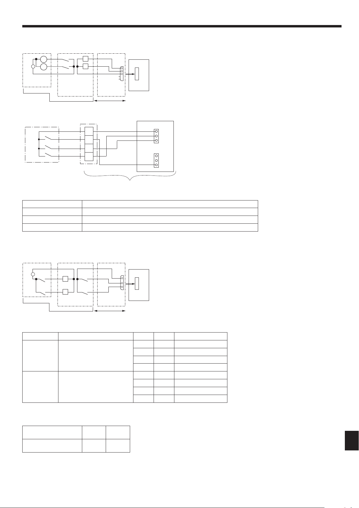
25
GB
8. Specialfunctions
A Distant control board
B Relay circuit
C External output adapter (PAC-SA88HA-E)
D Outdoor unit control board
E Lamp power supply
F Procure locally
G Max. 10 m
L1: Error display lamp
L2: Compressor operation lamp
X, Y: Relay (Coil standard of 0.9W or less for DC 12V)
X, Y: Relay (DC1mA)
The silent mode and the demand control are selected by switching the DIP switch 9-2 on outdoor controller board.
It is possible to set it to the following power consumption (compared with ratings) by setting SW1, 2.
Outdoor controller board DIP SW9-2 SW1 SW2 Function
Silent mode
(Cooling only)
OFF OFF OFF Normal
ON OFF Silent mode
OFF ON Super silent mode 1
ON ON Super silent mode 2
Demand control ON OFF OFF 100%(Normal)
ON OFF 75%
ON ON 50%
OFF ON 0% (Stop)
A Remote control panel
B Relay circuit
CExternalinputadapter(PAC-SC36NA-E)
D Outdoor unit control board
E Relay power supply
F Procure locally
G Max. 10 m
CN51
X
5
4
3
A C
D
5
E
1
B
G
Y
F
~
Y
X
L1
L2
1
3
A C
D
E
B
G
F
CN3D
X
Y
SW1
SW2
1
2
3
~
Y
X
8.1. OUTDOORUNITINPUT/OUTPUTCONNECTOR
•State(CN51)
•SilentMode/DemandControl(CN3D)
•Externalstaticpressuremode(30Pa)
Theexternalstaticpressuremode(30Pa)isenabledbyswitchingtheDIPswitchSW6-5ontheoutdoorcontrollerboardtoON.
However, the silent mode cannot be used when this mode is enabled.
Outdoor controller board DIP
SW6-5
ON OFF
External static pressure mode
(30 Pa)
Enabled Disabled
Tousethisfunction,DIPswitchSW5-1mustbesettoOFFandtheexistingCN3SandCN3Dleadwiresmustberemoved.Inaddition,thisfunctioncannotbeusedatthe
same time as the Demand Response Modes above.
The wiring between B and C is completed before shipping from the factory.
ThisproductiscapableofallthreeDemandResponseMode(DRM1,2,3).(DREDcomplianttoAS/NZS4755.3.1:2012)
Demand Response Mode Description
DRM1 Compressor Off.
DRM2 Total electrical energy consumption of the system is not more than 50%.
DRM3 Total electrical energy consumption of the system is not more than 75%.
•DemandResponseMode(CN3S,CN3D)
CN3D
CN3S
1
3
1
3
RD
BN
YE
WH
1
2
3
C
Common
DRM3
DRM2
DRM1
A
C
B
A DRED (Demand controller)
B Terminal block
C Outdoor unit control board
Input:12 V DC, 1mA
RG79Y960H01.indb 25 2018/02/09 14:31:10
26
GB
RemoteControllerdisplay
(PAR-33MAA)
WARNING
■ Askyourdealerortechnicalrepresentativetoinstalltheunit.
Any deficiency caused by your own installation may result in an
electricshockorre.
■ Ensurethatinstallationworkisdonecorrectlyfollowingthis
instructionmanual.
Anydeciencycausedbyinstallationmayresultinanelectricshock
orre.
■ Firmlyconnectthewiringusingthespeciedcables.
Carefullycheckthatthecablesdonotexertanyforcesonthe
terminals.
Improperwiringconnectionsmayproduceheatandpossiblyare.
■ Nevertryanymodication.
Anydeciencycausedbyyourmodicationorrepairmayresultin
anelectricshockorre.Consultwithyourdealeraboutrepair.
■
Allelectricalworkmustbeperformedbyalicensedtechnician,
accordingtolocalregulationsandtheinstructionsgiveninthis
manual.
Anylack ofelectriccircuitoranydeciencycausedbyinstallation
mayresultinanelectricshockorre.
■ Donotmoveandre-installthisdeviceyourself.
Any deficiency caused by installation may result in an electric
shockorre.Askyourdistributororspecialvendorformovingand
installation.
■ Stoptheoperationifanymalfunctionoccurs.
If malfunction occurs (burning smell, etc.) stop the operation
and turn off the power supply. Contact your dealer or technical
representative. If the controller continues to operate after a
malfunctionoccurs,thismaycausedamage,electricshockorre.
■ Donotturnonthemainpoweruntilinstallationhasbeen
completed.
Doingsomayresultinelectricshockorre.
CAUTION
■ Wiresothatitdoesnotreceiveanytension.
Tensionmaycausewirebreakage,heatingorre.
■ Usestandardwiresincompliancewiththecurrentcapacity.
Afailuretothismayresultinanelectricleakage,heatingorre.
■ Donotwashwithwater.
Doing so may cause an electric shock or malfunction.
■ Donotconnectthedemandcontroltransmissioncabletothe
terminalblockforpowersupply.
■ Donotpull,extremelybendorapplystrongpressureonthe
wiretopreventfailure.
■ DonotscrewDREDtooutdoorunit.
■ DonotputDREDinoutdoorunit.
■ Secureelectricalwiringaboveclamp.
■ DonotgetDREDwirecaughtinthepanel.
■ Securethepowersupplycord,indoor/outdoorunitconnecting
wireandDREDwirewiththeclampandband.
ThebandisnotusedforthePUMY-SP•VKMD.
Fri
Mode Temp. Fan
Room
Cool AutoSet temp.
will appear on the Main display while the product is
operating in a demand response mode.
9. Installationandoperationmanualfordemandresponse(DRED)
ThisunithasdemandresponsecapabilitywhichiscompliantwithAS/NZS4755.3.1:2012.
To activate this function, you need to make a contract with remote agents such as electric supply company, then this unit should be connected to Demand response enabling
devise (DRED). For further information, consult your dealer. This unit supports 3 Demand Response Modes (DRMs): DRM1, DRM2 and DRM3.
RG79Y960H01.indb 26 2018/02/09 14:31:11
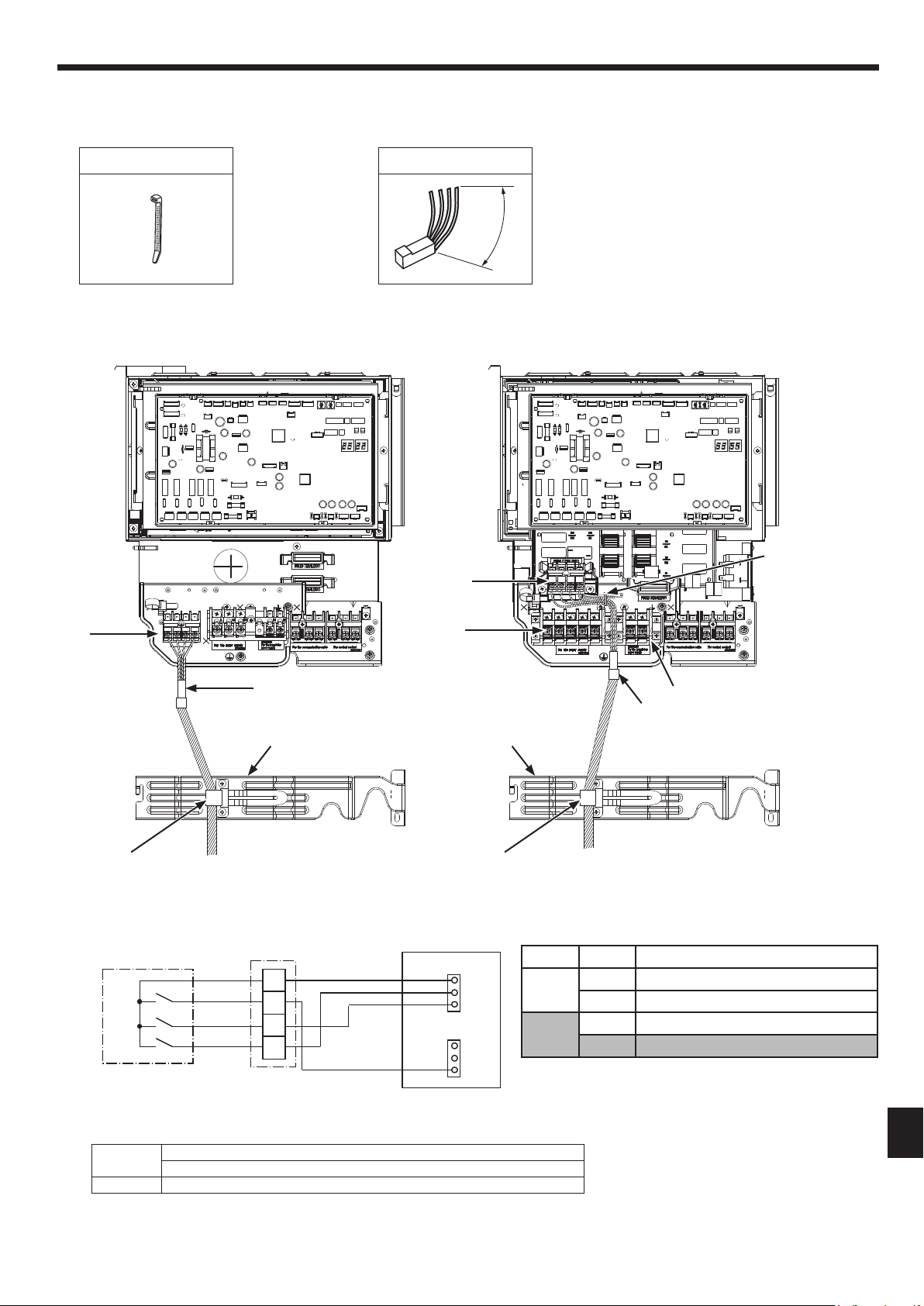
27
GB
9.1. PartsList
9.2. Installationprocedure
9.3. WhenconnectingtheDRED.
1
Bandx1
CN3D
CN3S
1
3
1
3
RD
BN
YE
WH
1
2
3
C
Common
DRM3
DRM2
DRM1
DRED (Demand controller)
Terminal block
Outdoor unit control board
Input:12VDC, 1mA
DipSW setting
SW5-1 SW9-2 Function
OFF OFF Silent Mode
ON Existing Demand Mode
ON OFF Silent Mode
ON Demand Response Mode (DRM)
●Theunitissettodefaultsettingsasintheshadedarea(Demand
ResponseMode(DRM)(SW5-1:ON,SW9-2:ON))whenshipped.
●Refertotheservicemanualfordetailsaboutthefunctionsofthe
unit other than Demand Response Mode (DRM).
A
DRMcablex1
M
i
n
.
1
0
0
m
m
●ACCESSORIES
(Check the following parts before installation.)
●PARTSTOBEPROVIDEDATYOURSITE
■
PUMY-SP•VKMD
■
PUMY-SP•YKMD
9. Installationandoperationmanualfordemandresponse(DRED)
Model
Wirespecications
Demand control signal transmission cable *1
Outdoor unit 0.5 - 1.5 mm²
*1 UsewiresinconformitywithdesignAS/NZS5000.2.
1
Band
Fix the DRM cable
with lead wire.
A
DRM cable
Pass the DRM cable between TB1
and TB1B.
TBD1
TB1
TB1B
TBD1
A
DRM cable
Valve bed Valve bed
Fix by clamp
●ThebandisnotusedforthePUMY-SP•VKMD.
Fix by clamp
RG79Y960H01.indb 27 2018/02/09 14:31:14

28
GB
9. Installationandoperationmanualfordemandresponse(DRED)
9.4. Demandresponsemode
ThisunithasdemandresponsecapabilitywhichiscompliantwithAS/NZS4755.3.1:2012.
To activate this function, you need to make a contract with remote agents such as electric supply company, then this unit should be connected to Demand response enabling
devise (DRED). For further information, consult your dealer.
Demandresponserepresentstheautomatedalterationofanelectricalproduct’snormalmodeofoperationinresponsetoaninitiatingsignaloriginatingfromordened
by a remote agent.
This unit supports 3 Demand Response Modes (DRMs).
DRM Description of operation in this mode
DRM 1
Compressor off
The air conditioner does not perform cooling or heating operation during the demand response event.
DRM 2
The air conditioner continues to perform cooling or heating operation during the demand response event, but the electrical energy consumed by the
air conditioner in a half hour period is not more than 50% of the total electrical energy that would be consumed if operating at the rated capacity in a
half hour period.
DRM 3
The air conditioner continues to perform cooling or heating operation during the demand response event, but the electrical energy consumed by the
air conditioner in a half hour period is not more than 75% of the total electrical energy that would be consumed if operating at the rated capacity in a
half hour period.
Note:
• DRMisautomaticallyactivatedorreleasedaccordingtothesignalsfromDRED.
DRM cannot be invalidated or changed manually.
• YoumightfeelthisunitdoesnotsufcientlyperformcoolingorheatingoperationduringDRM.
• OperationsettingscanbechangedasusualwiththeremotecontrollerduringDRM.
However, you might not feel cool or warm enough as DRM is prioritized.
• WhenthisunitreceivestheDRM1signal,theresponsetimeuntiltheDRM1modeisactivatediswithin60sec.
However, if the maintenance and safety modes are activated, those modes have priority.
• TheterminalblockfortheDREDsatisestheELVrequirements.
RG79Y960H01.indb 28 2018/02/09 14:31:14

A4_white_tombo.indd 1 2016/04/25 10:16:47

A4_white_tombo.indd 1 2016/04/25 10:16:47

A4_white_tombo.indd 1 2016/04/25 10:16:47
Made in Thailand
Printed in Thailand
RG79Y960H01
HEADOFFICE:TOKYOBUILDING,2-7-3,MARUNOUCHI,CHIYODA-KU,TOKYO100-8310,JAPAN
Pleasebesuretoputthecontactaddress/telephonenumberon
this manual before handing it to the customer.
This product is designed and intended for use in the residential,
commercial and light-industrial environment.
RG79Y960H01.indb 1 2018/02/09 14:31:14