Predator Triton 515-51
SERVICE GUIDE

ii
Revision History
Refer to the table below for the updates made to this Predator Triton 515-51 Service Guide.
Service guide files and updates are available on the ACER/CSD website. For more
information, go to
http://gcsd.acer.com.tw/GCSD_Portal/. The information in this guide is subject
to change without notice.
Disclaimer
The information in this guide is subject to change without notice.
There are no representations or warranties, either expressed or implied, with respect to the
contents hereof and specifically disclaims any warranties of merchantability or fitness for any
particular purpose. The software described in this manual is sold or licensed "as is". Should
the programs prove defective following their purchase, the buyer (not the manufacturer,
distributor, or its dealer) assumes the entire cost of all necessary servicing, repair, and any
incidental or consequential damages resulting from any defect in the software.
Copyright
© 2019 by Acer Incorporated. All rights reserved. No part of this publication may be
reproduced, transmitted, transcribed, stored in a retrieval system, or translated into any
language or computer language, in any form or by any means, electronic, mechanical,
magnetic, optical, chemical, manual or otherwise, without the prior written permission of Acer
Incorporated.
HDMI, the HDMI logo, and High Definition Multimedia Interface are trademarks or registered
trademarks of HDMI Licensing, LLC in the United States and other countries.
Date Version Chapter Updates
01-17-2019 FIRST DRAFT
01-28-2019 V1.00

iii
Conventions
The following conventions are used in this manual:
WARNING:
!
Indicates a potential for personal injury.
CAUTION:
!
Indicates a potential loss of data or damage to equipment.
IMPORTANT:
+
Indicates information that is important to know for the proper completion of a
procedure, choice of an option, or completing a task.
The following typographical conventions are used in this document:
Book titles, directory names, file names, path names, and program/process names are
shown in italics.
Example:
the DRS5 User's Guide
/usr/local/bin/fd
the /TPH15spool_M program
Computer output (text that represents information displayed on a computer screen,
such as menus, prompts, responses to input, and error messages) are shown in
constant width.
Example:
[01] The server has been stopped
User input (text that represents information entered by a computer user, such as
command names, option letters, and words) are shown in constant width bold.
Variables contained within user input are shown in angle brackets (< >).
Example:
At the prompt, type run <file name> -m
Keyboard keys are shown in bold italics.
Example:
After entering data, press Enter.

iv
General information 0
Before using this information and the product it supports, read the following general
information.
This service guide provides you with all technical information relating to the basic
configuration for Acer’s global product offering. To better fit local market requirements and
enhance product competitiveness, your regional office may have decided to extend the
functionality of a machine (such as add-on cards, modems, or extra memory capabilities).
These localized features are not covered in this generic service guide. In such cases, contact
your regional office or the responsible personnel/channel to provide you with further technical
details.
When ordering FRU parts: Check the most up-to-date information available on your regional
Web or channel. If, for whatever reason, a part number change is made, it may not be noted
in this printed service guide.
Acer-authorized Service Providers: Your Acer office may have a different part number code
than those given in the FRU list in this service guide. You must use the list provided by your
regional Acer office to order FRU parts for repair and service of customer machines.

v
CHAPTER 1 - Hardware Specifications
Features . . . . . . . . . . . . . . . . . . . . . . . . . . . . . . . . . . . . . . . . . . . . .1-5
Operating System . . . . . . . . . . . . . . . . . . . . . . . . . . . . . . . . . . .1-5
Platform . . . . . . . . . . . . . . . . . . . . . . . . . . . . . . . . . . . . . . . . . . .1-5
System Memory. . . . . . . . . . . . . . . . . . . . . . . . . . . . . . . . . . . . .1-5
Display. . . . . . . . . . . . . . . . . . . . . . . . . . . . . . . . . . . . . . . . . . . .1-5
Graphics . . . . . . . . . . . . . . . . . . . . . . . . . . . . . . . . . . . . . . . . . .1-6
Storage Subsystem . . . . . . . . . . . . . . . . . . . . . . . . . . . . . . . . . .1-6
Audio Subsystem. . . . . . . . . . . . . . . . . . . . . . . . . . . . . . . . . . . .1-6
Communication . . . . . . . . . . . . . . . . . . . . . . . . . . . . . . . . . . . . .1-7
Privacy Control . . . . . . . . . . . . . . . . . . . . . . . . . . . . . . . . . . . . .1-7
Power Adapter and Battery . . . . . . . . . . . . . . . . . . . . . . . . . . . .1-7
Keyboard and Pointing Device . . . . . . . . . . . . . . . . . . . . . . . . .1-8
I/O Ports. . . . . . . . . . . . . . . . . . . . . . . . . . . . . . . . . . . . . . . . . . .1-8
Software and Tools . . . . . . . . . . . . . . . . . . . . . . . . . . . . . . . . . .1-9
Optional items . . . . . . . . . . . . . . . . . . . . . . . . . . . . . . . . . . . . . .1-9
Warranty . . . . . . . . . . . . . . . . . . . . . . . . . . . . . . . . . . . . . . . . . .1-9
Dimensions and Weight. . . . . . . . . . . . . . . . . . . . . . . . . . . . . . .1-10
Environment. . . . . . . . . . . . . . . . . . . . . . . . . . . . . . . . . . . . . . . .1-10
Notebook Tour. . . . . . . . . . . . . . . . . . . . . . . . . . . . . . . . . . . . . . . .1-11
Open Front View . . . . . . . . . . . . . . . . . . . . . . . . . . . . . . . . . . . .1-11
Left View . . . . . . . . . . . . . . . . . . . . . . . . . . . . . . . . . . . . . . . . . .1-12
Right View . . . . . . . . . . . . . . . . . . . . . . . . . . . . . . . . . . . . . . . . .1-13
Base View . . . . . . . . . . . . . . . . . . . . . . . . . . . . . . . . . . . . . . . . . 1-14
Touchpad Basics . . . . . . . . . . . . . . . . . . . . . . . . . . . . . . . . . . . .1-15
Touchpad Gestures . . . . . . . . . . . . . . . . . . . . . . . . . . . . . . . . . .1-15
Keyboard . . . . . . . . . . . . . . . . . . . . . . . . . . . . . . . . . . . . . . . . . .1-16
D2D Recovery . . . . . . . . . . . . . . . . . . . . . . . . . . . . . . . . . . . . . .1-19
System Block Diagram . . . . . . . . . . . . . . . . . . . . . . . . . . . . . . .1-19
Specification Tables . . . . . . . . . . . . . . . . . . . . . . . . . . . . . . . . . . .1-20
CHAPTER 2 - System Utilities
BIOS Setup Utility . . . . . . . . . . . . . . . . . . . . . . . . . . . . . . . . . . . . .2-3
Navigating the BIOS Utility . . . . . . . . . . . . . . . . . . . . . . . . . . . .2-3
BIOS Menus . . . . . . . . . . . . . . . . . . . . . . . . . . . . . . . . . . . . . . . . . .2-4
Information. . . . . . . . . . . . . . . . . . . . . . . . . . . . . . . . . . . . . . . . .2-4
Main. . . . . . . . . . . . . . . . . . . . . . . . . . . . . . . . . . . . . . . . . . . . . .2-6
Advanced. . . . . . . . . . . . . . . . . . . . . . . . . . . . . . . . . . . . . . . . . .2-8
Security . . . . . . . . . . . . . . . . . . . . . . . . . . . . . . . . . . . . . . . . . . .2-9
Boot . . . . . . . . . . . . . . . . . . . . . . . . . . . . . . . . . . . . . . . . . . . . . .2-13

vi
Exit. . . . . . . . . . . . . . . . . . . . . . . . . . . . . . . . . . . . . . . . . . . . . . .2-14
BIOS Flash Utilities . . . . . . . . . . . . . . . . . . . . . . . . . . . . . . . . . . . .2-15
Removing the HDD Password . . . . . . . . . . . . . . . . . . . . . . . . . . .2-16
Removing the HDD Password (DOS) . . . . . . . . . . . . . . . . . . . .2-16
Removing the HDD Password (Windows) . . . . . . . . . . . . . . . . .2-17
Removing BIOS Passwords . . . . . . . . . . . . . . . . . . . . . . . . . . . . .2-18
Removing the BIOS Passwords (Hardware Gap) . . . . . . . . . . .2-18
Removing the BIOS Passwords (Software). . . . . . . . . . . . . . . .2-19
Using DMI Utility . . . . . . . . . . . . . . . . . . . . . . . . . . . . . . . . . . . . . .2-22
Using DMI Utility . . . . . . . . . . . . . . . . . . . . . . . . . . . . . . . . . . . .2-22
CHAPTER 3 - Machine Maintenance
Machine Disassembly and Replacement . . . . . . . . . . . . . . . . . .3-5
Recommended Equipment . . . . . . . . . . . . . . . . . . . . . . . . . . . .3-5
Replacement Requirements . . . . . . . . . . . . . . . . . . . . . . . . . . .3-5
Pre-disassembly Instructions. . . . . . . . . . . . . . . . . . . . . . . . . . .3-6
Disassembly Process . . . . . . . . . . . . . . . . . . . . . . . . . . . . . . . . . .3-7
Main Unit Disassembly Process . . . . . . . . . . . . . . . . . . . . . . . . .3-8
Main Unit Disassembly Flowchart . . . . . . . . . . . . . . . . . . . . . . .3-8
Removing the Lower Case . . . . . . . . . . . . . . . . . . . . . . . . . . . .3-9
Removing the Battery Pack . . . . . . . . . . . . . . . . . . . . . . . . . . . .3-11
Removing the WLAN Module . . . . . . . . . . . . . . . . . . . . . . . . . .3-13
Removing the RTC Battery . . . . . . . . . . . . . . . . . . . . . . . . . . . .3-15
Removing the DC-In Cable . . . . . . . . . . . . . . . . . . . . . . . . . . . .3-16
Removing the Mainboard. . . . . . . . . . . . . . . . . . . . . . . . . . . . . .3-17
Removing the Touchpad Module. . . . . . . . . . . . . . . . . . . . . . . .3-23
Removing the Left and Right Speakers . . . . . . . . . . . . . . . . . . .3-25
Removing the WLAN Antenna. . . . . . . . . . . . . . . . . . . . . . . . . .3-27
Removing the Turbo Key Module . . . . . . . . . . . . . . . . . . . . . . .3-29
Removing the Memory Modules . . . . . . . . . . . . . . . . . . . . . . . .3-32
Removing the SSD Modules . . . . . . . . . . . . . . . . . . . . . . . . . . .3-34
Removing the Thermal Module . . . . . . . . . . . . . . . . . . . . . . . . .3-36
Removing the Upper Case . . . . . . . . . . . . . . . . . . . . . . . . . . . .3-39
LCD Module Disassembly Process . . . . . . . . . . . . . . . . . . . . . . .3-41
LCD Module Disassembly Flowchart. . . . . . . . . . . . . . . . . . . . .3-41
Removing the LCD Bezel . . . . . . . . . . . . . . . . . . . . . . . . . . . . .3-42
Removing the LCD Hinge Brackets . . . . . . . . . . . . . . . .
. . . . . .3-43
Removing the LCD Panel . . . . . . . . . . . . . . . . . . . . . . . . . . . . .3-44

vii
Removing the Camera Module . . . . . . . . . . . . . . . . . . . . . . . . .3-47
LCD Module Reassembly Process . . . . . . . . . . . . . . . . . . . . . . .3-49
Replacing the Camera Module . . . . . . . . . . . . . . . . . . . . . . . . .3-49
Replacing the LCD Panel . . . . . . . . . . . . . . . . . . . . . . . . . . . . .3-51
Replacing the LCD Hinge Brackets . . . . . . . . . . . . . . . . . . . . . .3-56
Replacing the LCD Bezel. . . . . . . . . . . . . . . . . . . . . . . . . . . . . .3-57
Main Unit Reassembly Process . . . . . . . . . . . . . . . . . . . . . . . . . .3-58
Replacing the Upper Case. . . . . . . . . . . . . . . . . . . . . . . . . . . . .3-58
Replacing the Thermal Module . . . . . . . . . . . . . . . . . . . . . . . . .3-59
Replacing the SSD Modules . . . . . . . . . . . . . . . . . . . . . . . . . . .3-61
Replacing the Memory Module . . . . . . . . . . . . . . . . . . . . . . . . .3-62
Replacing the Turbo Key Module . . . . . . . . . . . . . . . . . . . . . . .3-64
Replacing the WLAN Antenna . . . . . . . . . . . . . . . . . . . . . . . . . .3-67
Replacing the Left and Right Speakers . . . . . . . . . . . . . . . . . . .3-68
Replacing the Touchpad Module . . . . . . . . . . . . . . . . . . . . . . . .3-70
Replacing the Mainboard. . . . . . . . . . . . . . . . . . . . . . . . . . . . . .3-72
Replacing the DC-In Cable . . . . . . . . . . . . . . . . . . . . . . . . . . . .3-78
Replacing the RTC Battery . . . . . . . . . . . . . . . . . . . . . . . . . . . .3-79
Replacing the WLAN Module. . . . . . . . . . . . . . . . . . . . . . . . . . .3-80
Replacing the Battery Pack . . . . . . . . . . . . . . . . . . . . . . . . . . . .3-82
Replacing the Lower Case. . . . . . . . . . . . . . . . . . . . . . . . . . . . .3-84
CHAPTER 4 - Troubleshooting
General Information . . . . . . . . . . . . . . . . . . . . . . . . . . . . . . . . . . .4-3
Power On Issues . . . . . . . . . . . . . . . . . . . . . . . . . . . . . . . . . . . .4-4
No Display Issues . . . . . . . . . . . . . . . . . . . . . . . . . . . . . . . . . . .4-5
LCD Failure . . . . . . . . . . . . . . . . . . . . . . . . . . . . . . . . . . . . . . . .4-8
Keyboard Failure . . . . . . . . . . . . . . . . . . . . . . . . . . . . . . . . . . . .4-9
Keyboard Backlight Failure . . . . . . . . . . . . . . . . . . . . . . . . . . . .4-10
Touchpad Failure. . . . . . . . . . . . . . . . . . . . . . . . . . . . . . . . . . . .4-11
Internal Speaker Failure . . . . . . . . . . . . . . . . . . . . . . . . . . . . . .4-12
Microphone Failure . . . . . . . . . . . . . . . . . . . . . . . . . . . . . . . . . .4-14
USB Failure . . . . . . . . . . . . . . . . . . . . . . . . . . . . . . . . . . . . . . . .4-15
WLAN Failure . . . . . . . . . . . . . . . . . . . . . . . . . . . . . . . . . . . . . .4-16
Thermal Unit Failure . . . . . . . . . . . . . . . . . . . . . . . . . . . . . . . . .4-17
Other Functions Failure . . . . . . . . . . . . . . . . . . . . . . . . . . . . . . .4-18
Intermittent Problems. . . . . . . . . . . . . . . . . . . . . . . . . . . . . . . . . .4-19
Undetermined Problems. . . . . . . . . . . . . . . . . . . . . . . . . . . . . . . .4-19
POST Codes . . . . . . . . . . . . . . . . . . . . . . . . . . . . . . . . . . . . . . . . .4-20

viii
CHAPTER 5 - Jumper and Connector Locations
Mainboard Layout . . . . . . . . . . . . . . . . . . . . . . . . . . . . . . . . . . . . .5-3
Clearing Password Check and BIOS Recovery . . . . . . . . . . . . .5-5
Clearing the BIOS Passwords . . . . . . . . . . . . . . . . . . . . . . . . . .5-5
Performing a BIOS Recovery . . . . . . . . . . . . . . . . . . . . . . . . . .5-6
CHAPTER 6 - FRU List
Predator Triton 515-51 Exploded Diagrams . . . . . . . . . . . . . . . .6-4
Main Assembly . . . . . . . . . . . . . . . . . . . . . . . . . . . . . . . . . . . . .6-4
LCD Assembly. . . . . . . . . . . . . . . . . . . . . . . . . . . . . . . . . . . . . .6-5
Predator Triton 515-51 FRU List . . . . . . . . . . . . . . . . . . . . . . . . .6-6
CHAPTER 7 - Test Compatible Components
Microsoft Windows 10 Environment Test. . . . . . . . . . . . . . . . . . 7-3
CHAPTER 8 - Online Support Information
Online Technical Support. . . . . . . . . . . . . . . . . . . . . . . . . . . . . . .8-3

CHAPTER 1
Hardware Specifications

1-2
Features . . . . . . . . . . . . . . . . . . . . . . . . . . . . . . . . . . . . . . . . . . . . .1-5
Operating System . . . . . . . . . . . . . . . . . . . . . . . . . . . . . . . . . . .1-5
Platform . . . . . . . . . . . . . . . . . . . . . . . . . . . . . . . . . . . . . . . . . . .1-5
System Memory. . . . . . . . . . . . . . . . . . . . . . . . . . . . . . . . . . . . .1-5
Display. . . . . . . . . . . . . . . . . . . . . . . . . . . . . . . . . . . . . . . . . . . .1-5
Graphics . . . . . . . . . . . . . . . . . . . . . . . . . . . . . . . . . . . . . . . . . .1-6
Storage Subsystem . . . . . . . . . . . . . . . . . . . . . . . . . . . . . . . . . .1-6
Audio Subsystem. . . . . . . . . . . . . . . . . . . . . . . . . . . . . . . . . . . .1-6
Communication . . . . . . . . . . . . . . . . . . . . . . . . . . . . . . . . . . . . .1-7
Privacy Control . . . . . . . . . . . . . . . . . . . . . . . . . . . . . . . . . . . . .1-7
Power Adapter and Battery . . . . . . . . . . . . . . . . . . . . . . . . . . . .1-7
Keyboard and Pointing Device . . . . . . . . . . . . . . . . . . . . . . . . .1-8
I/O Ports. . . . . . . . . . . . . . . . . . . . . . . . . . . . . . . . . . . . . . . . . . .1-8
Software and Tools . . . . . . . . . . . . . . . . . . . . . . . . . . . . . . . . . .1-9
Optional items . . . . . . . . . . . . . . . . . . . . . . . . . . . . . . . . . . . . . .1-9
Warranty . . . . . . . . . . . . . . . . . . . . . . . . . . . . . . . . . . . . . . . . . .1-9
Dimensions and Weight. . . . . . . . . . . . . . . . . . . . . . . . . . . . . . .1-10
Environment. . . . . . . . . . . . . . . . . . . . . . . . . . . . . . . . . . . . . . . .1-10
Notebook Tour. . . . . . . . . . . . . . . . . . . . . . . . . . . . . . . . . . . . . . . .1-11
Open Front View . . . . . . . . . . . . . . . . . . . . . . . . . . . . . . . . . . . .1-11
Left View . . . . . . . . . . . . . . . . . . . . . . . . . . . . . . . . . . . . . . . . . .1-12
Right View . . . . . . . . . . . . . . . . . . . . . . . . . . . . . . . . . . . . . . . . .1-13
Base View . . . . . . . . . . . . . . . . . . . . . . . . . . . . . . . . . . . . . . . . . 1-14
Touchpad Basics . . . . . . . . . . . . . . . . . . . . . . . . . . . . . . . . . . . .1-15
Touchpad Gestures . . . . . . . . . . . . . . . . . . . . . . . . . . . . . . . . . .1-15
Keyboard . . . . . . . . . . . . . . . . . . . . . . . . . . . . . . . . . . . . . . . . . .1-16
D2D Recovery . . . . . . . . . . . . . . . . . . . . . . . . . . . . . . . . . . . . . .1-19
System Block Diagram . . . . . . . . . . . . . . . . . . . . . . . . . . . . . . .1-19
Specification Tables . . . . . . . . . . . . . . . . . . . . . . . . . . . . . . . . . . .1-20
Computer Specifications . . . . . . . . . . . . . . . . . . . . . . . . . . . . . .1-20
Processor. . . . . . . . . . . . . . . . . . . . . . . . . . . . . . . . . . . . . . . . . .1-21
Processor Specifications . . . . . . . . . . . . . . . . . . . . . . . . . . . . . .1-21
System Memory. . . . . . . . . . . . . . . . . . . . . . . . . . . . . . . . . . . . .1-22
Graphics Controller . . . . . . . . . . . . . . . . . . . . . . . . . . . . . . . . . .1-23
System BIOS . . . . . . . . . . . . . . . . . . . . . . . . . . . . . . . . . . . . . . .1-23
Keyboard . . . . . . . . . . . . . . . . . . . . . . . . . . . . . . . . . . . . . . . . . .1-24
Solid State Drive (SSD) . . . . . . . . . . . . . . . . . . . . . . . . . . . . . . .1-24
LCD Panel . . . . . . . . . . . . . . . . . . . . . . . . . . . . . . . . . . . . . . . . .1-24
Supported GPU Resolutions . . . . . . . . . . . . . . . . . . . . . . . . . . .1-25
Supported Display Resolutions . . . . . . . . . . . . . . . . . . . . . . . . .1-26

1-3
Audio Codec . . . . . . . . . . . . . . . . . . . . . . . . . . . . . . . . . . . . . . .1-26
Audio Interface. . . . . . . . . . . . . . . . . . . . . . . . . . . . . . . . . . . . . .1-27
Webcam. . . . . . . . . . . . . . . . . . . . . . . . . . . . . . . . . . . . . . . . . . .1-27
LAN . . . . . . . . . . . . . . . . . . . . . . . . . . . . . . . . . . . . . . . . . . . . . .1-27
Wireless LAN . . . . . . . . . . . . . . . . . . . . . . . . . . . . . . . . . . . . . . .1-28
USB Interface . . . . . . . . . . . . . . . . . . . . . . . . . . . . . . . . . . . . . .1-28
HDMI Port . . . . . . . . . . . . . . . . . . . . . . . . . . . . . . . . . . . . . . . . .1-28
System LED Indicators . . . . . . . . . . . . . . . . . . . . . . . . . . . . . . .1-28
Battery Pack . . . . . . . . . . . . . . . . . . . . . . . . . . . . . . . . . . . . . . .1-29
AC Adapter . . . . . . . . . . . . . . . . . . . . . . . . . . . . . . . . . . . . . . . .1-29
System Power Management . . . . . . . . . . . . . . . . . . . . . . . . . . .1-29
System Interrupt Specification . . . . . . . . . . . . . . . . . . . . . . . . .1-30

1-4

Hardware Specifications and Configurations 1-5
Hardware Specifications and Configurations
This chapter lists the features and specifications of the Predator Triton 515-51 computer. The items
listed in this section are for reference only. The exact configuration of your computer depends on the
model purchased.
Features 0
The following is a summary of the computer’s many features.
Operating System 0
Windows® 10 Home 64-bit
Platform 0
Intel
®
Coffee Lake H platform
Intel
®
Core™ i7-8750H processor (9 MB L3 Cache, 2.2 GHz with Turbo Boost up
to 4.1 GHz, DDR4 2666 MHz, 45 W), supporting Intel
®
64 architecture, Intel
®
Smart Cache
Intel
®
Core™ i5-8300H processor (8 MB L3 Cache, 2.3 GHz with Turbo Boost up
to 4.0 GHz, DDR4 2666 MHz, 45 W), supporting Intel
®
64 architecture, Intel
®
Smart Cache
Chipset: Mobile Intel
®
HM370 Express Chipset (Cannon Lake)
System Memory 0
Two DIMM slots support DDR4 SO-DIMM
32 GB maximum memory capacity (using two 16 GB modules)
Supports dual channel
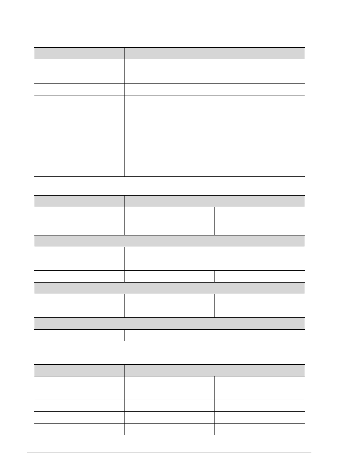
Display 0
15.6" display with IPS (In-Plane Switching) Technology, Full HD
1920 × 1080 resolution, 16:9 aspect ratio
16.9 million colors, NTSC 72%, 300-nit brightness
supports 144 Hz, 3 ms Overdrive and G-sync
Wide viewing angle up to 170°
Ultra-slim design
Mercury free, environment friendly

1-6 Hardware Specifications and Configurations
Graphics 0
NVIDIA
®
GeForce
®
RTX 2080 / 2070 with 8 GB of dedicated GDDR6 VRAM or
NVIDIA
®
GeForce
®
RTX 2060 with 6 GB of dedicated GDDR6 VRAM
Supports NVIDIA
®
CUDA™, PhysX™, PureVideo
®
HD technology, GPU Battery Boost
technology, ShadowPlay technology, GameStream technology, Multi-Frame sampled
Anti-Aliasing (MFAA), Dynamic Super Resolution (DSR), Voxel Global Illumination
(VXGI). Microsoft
®
DirectX
®
12, OpenGL
®
4.5, OpenCL™ 1.1
Triple independent display support
Intel
®
HD Graphics, Gen 8-LP, 16EU, 600 MHz, supporting OpenGL
®
3.0, OpenCL™
2.0, Microsoft
®
DirectX
®
12
Internal and external resolutions and refresh rate supported:
Storage Subsystem 0
Solid state drive 0
M.2 PCIe Gen3 8 Gb/s up to 4 lanes, NVMe
256 GB / 512 GB
Audio Subsystem 0
Waves MaxxAudio
®
sound technology, featuring MaxxBass
®
,MaxxVolume
®
,
MaxxDialog™ and hyper-realistic 3D Audio using Waves Nx™
Acer PurifiedVoice™ technology with two built-in microphones featuring far-field
pickup, keystroke suppression, voice tracking, adaptive beam forming, voice
recognition enhancement, three pre-defined modes: voice recognition, personal call,
conference call
Acer TrueHarmony™ technology for lower distortion, wider frequency range,
headphone-like audio and powerful sound
Compatible with Cortana with Voice
Certified for Skype for Business
800 x 600, 144 Hz 1280 x 1024, 144 Hz
1024 x 768, 144 Hz 1360 x 768, 144 Hz
1152 x 864, 144 Hz 1366 x 768, 144 Hz
1280 x 600, 144 Hz 1400 x 1050, 144 Hz
1280 x 720, 144 Hz 1440 x 900, 144 Hz
1280 x 768, 144 Hz 1600 x 900, 144 Hz
1280 x 800, 144 Hz 1680 x 1050, 144 Hz
1280 x 960, 144 Hz 1920 x 1080, 144 Hz
Maximum Resolution HDMI: 3840 x 2560, 60 Hz

Hardware Specifications and Configurations 1-7
Two built-in stereo speakers
Realtek ALC289
Communication 0
Webcam 0
1.0 MP HD webcam, featuring:
1280 × 720 resolution
720p HD audio/video recording
Super high dynamic range imaging (SHDR)
Wireless and networking 0
WLAN:
Killer™ Wireless-AC 1550 / 1550i
802.11a/b/g/n/ac wireless LAN
Dual Band (2.4 GHz and 5 GHz)
2x2 MU-MIMO technology
WPAN:
Bluetooth
®
5.0
LAN:
Gigabit Ethernet, Secure Wake Over Internet (SWOI)
Killer™ LAN E3000
Privacy Control 0
BIOS supervisor, user, and HDD passwords
Kensington lock slot
Power Adapter and Battery 0
3-pin 180 W AC adapter
8436 Wh 5550 mAh 15.2 V 4-cell Li-polymer battery pack
Battery life: Up to 8 hours (based on MobileMark
®
2014 test results)
ACPI 5.0 CPU power management standard: supports Standby and Hibernation
power-saving modes

1-8 Hardware Specifications and Configurations
Keyboard and Pointing Device 0
Keyboard 0
86-/87-/90-key Acer FineTip™ RGB backlit keyboard
Hotkeys for volume and brightness level, wireless and sleep functions, and display and
touchpad toggle
Windows
®
and Application keys
Inverted “T” cursor keys
Turbo key and power button key
Multilanguage support
Touchpad 0
Multi-gesture touchpad, supporting two-finger scroll and pinch.
Gestures to open Cortana, Action Center, multitasking
Swipes access charms, application commands and previous applications
Microsoft Precision Touchpad Certification
Moisture resistant
Media Keys 0
Media control keys (printed on keyboard): volume up, volume down
I/O Ports 0
mini-DisplayPort™ 1.4
HDMI
®
2.0 port with HDCP support
USB Type-C™ port supporting:
USB 3.1 Gen 2 (up to 10 Gbps)
DisplayPort over USB-C
Thunderbolt™ 3
Ethernet (RJ-45) port
Three USB 3.1 Gen 1 ports with one featuring power-off USB charging
Microphone-in jack
Headphone/speaker jack

Hardware Specifications and Configurations 1-9
Software and Tools 0
Windows Desktop Apps 0
Content
Netflix
Games
XSplit Gamecaster
In-House
Acer Configuration Manager
Acer Product Registration
PredatorSense 3.0
Security
Norton™ Internet Security
Windows Store Apps 0
In-House
Acer Care Center
Acer Collection
Quick Access
Productivity
Cyberlink
®
PhotoDirector 8
Cyberlink
®
PowerDirector 14
Too l s
MS Remote Desktop
MS Translator
Optional items 0
3-pin 180 W AC adapter
Warranty 0
One-year International Travelers Warranty (ITW)

1-10 Hardware Specifications and Configurations
Dimensions and Weight 0
Dimensions 0
Width × Depth × Height: 358.5 (W) x 255 (D) x 17.9 (H) mm (14.11 x 10.04 x 0.7
inches)
Weight 0
2.1 kg (4.63 lbs.) with 4-cell battery pack
Environment 0
Temperature:
Operating: 0 to 40 °C
Non-operating: -20 to 60 °C
Humidity (non-condensing):
Operating: 0% to 80%
Non-operating: 0% to 80%
Hardware Specifications and Configurations 1-11
Notebook Tour 0
This section provides an overview of the features and functions of the notebook.
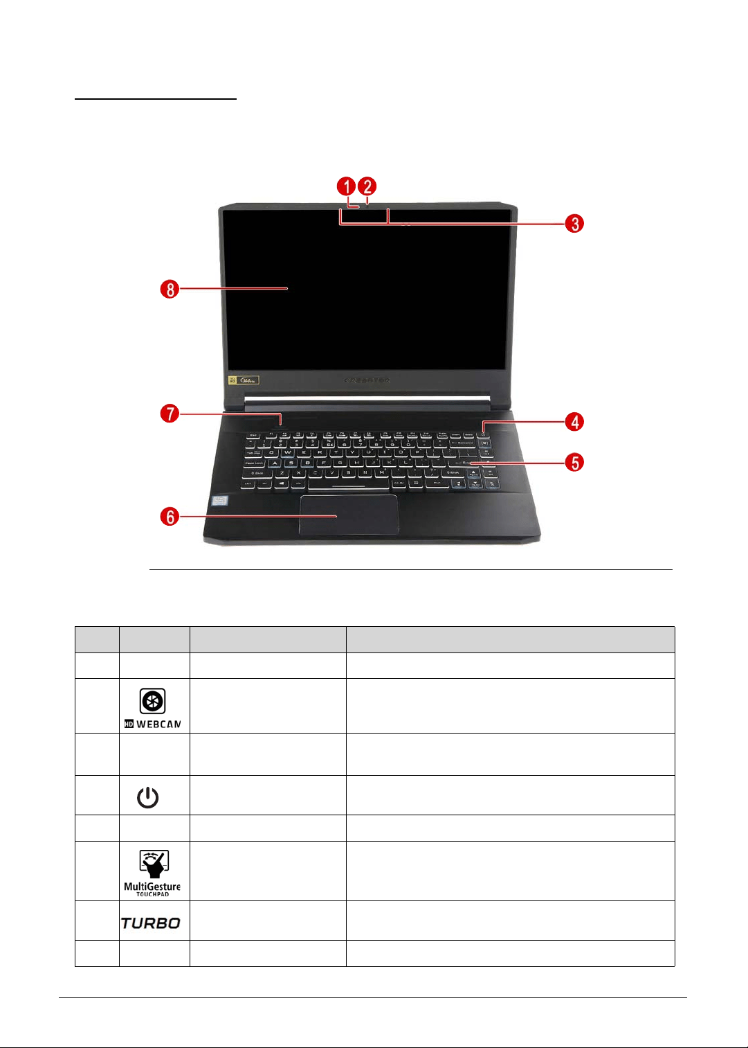
Open Front View 0
Figure 1-1. Open Front View
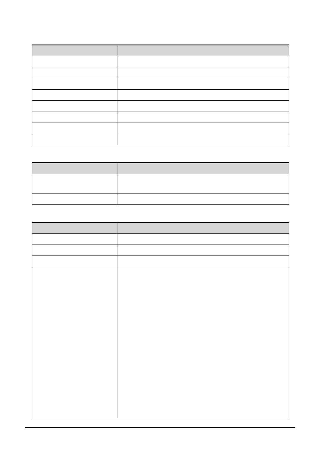
Table 1-1. Open Front View
No. Icon Item Description
1 Webcam LED Camera status indicator.
2 Integrated HD webcam Web camera for video communication.
3 Integrated microphone Internal microphone for sound recording and video
communication.
4 Power button Turns the computer on and off.
5 Keyboard For entering data into your computer.
6 Multi-Gesture
Touchpad
Touch-sensitive pointing device which functions like
a computer mouse.
7 Turbo key Switches overclocking and fan speed level.
8 Display screen Displays computer output.
1-12 Hardware Specifications and Configurations
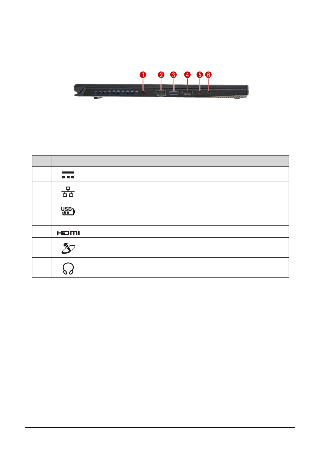
Left View 0
Figure 1-2. Left View
Table 1-2. Left View
No. Icon Item Description
1 DC-in jack Connects to the AC adapter.
2 Ethernet (RJ-45)
port
Connects to an 110/100/1000Mbps/2.5Gbps-based
Ethernet network.
3 USB 3.1 Gen 1 port
with power-off
charging
Connects to USB devices (e.g., USB mouse, USB
camera).
4 HDMI port Supports high definition digital video connections.
5 Microphone-in jack Connects to an external microphone for recording
audio.
6 Headset/speaker
jack
Connects to audio-out devices (e.g., speakers,
headphones)
Hardware Specifications and Configurations 1-13
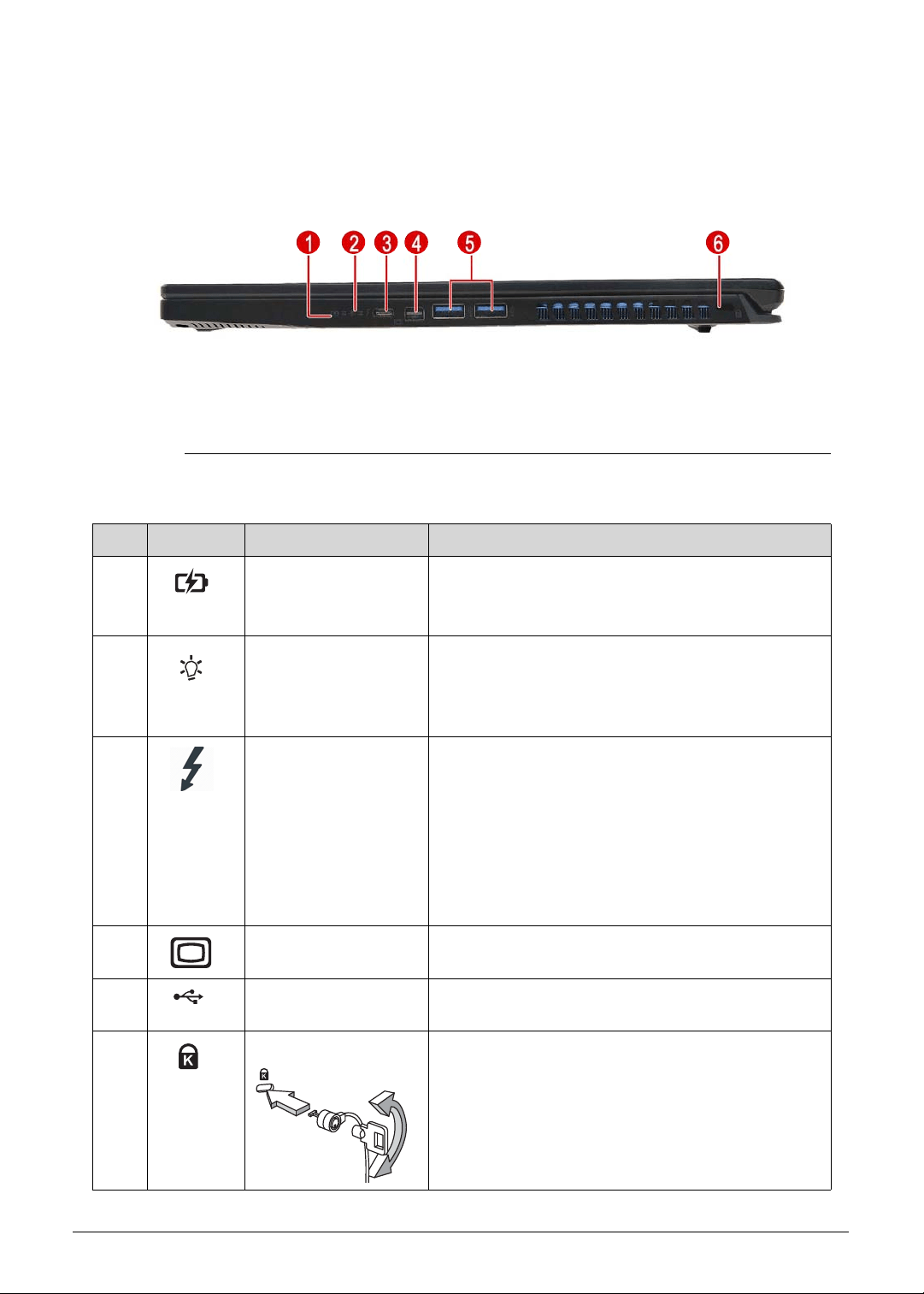
Right View 0
Figure 1-3. Right View
Table 1-3. Right View
No. Icon Item Description
1 Battery indicator Indicates the computer’s battery status.
Blue: The computer is in AC mode.
Blinking amber: The battery is charging.
2 Power indicator Indicates the computer’s power status.
Blue: The computer is turned on.
Blinking amber: The computer is in power-saving
mode.
3 USB Type-C/
Thunderbolt 3 port
Connects to USB devices with a USB Type-C
connector. Supports Thunderbolt™ 3 and
DisplayPort over USB-C displays.
USB 3.1 Gen 2 with transfer speeds up to 10
Gbps.
Supports DisplayPort™ audio/video output.
Compatible with Thunderbolt™ 3
Delivers up to 3A at 5V DC for USB charging.
4 mini-DisplayPort Connects to a display device using the
high-definition mini-DisplayPort interface.
5 USB 3.1 Gen 1 ports Connects to USB devices (e.g., USB mouse, USB
camera).
6 Kensington lock slot Connects to a Kensington-compatible computer
security lock.
Note: Wrap the computer security lock cable
around an immovable object such as a table or the
handle of a locked drawer. Insert the lock into the
notch and turn the key to secure the lock. Some
keyless models are also available.
1-14 Hardware Specifications and Configurations
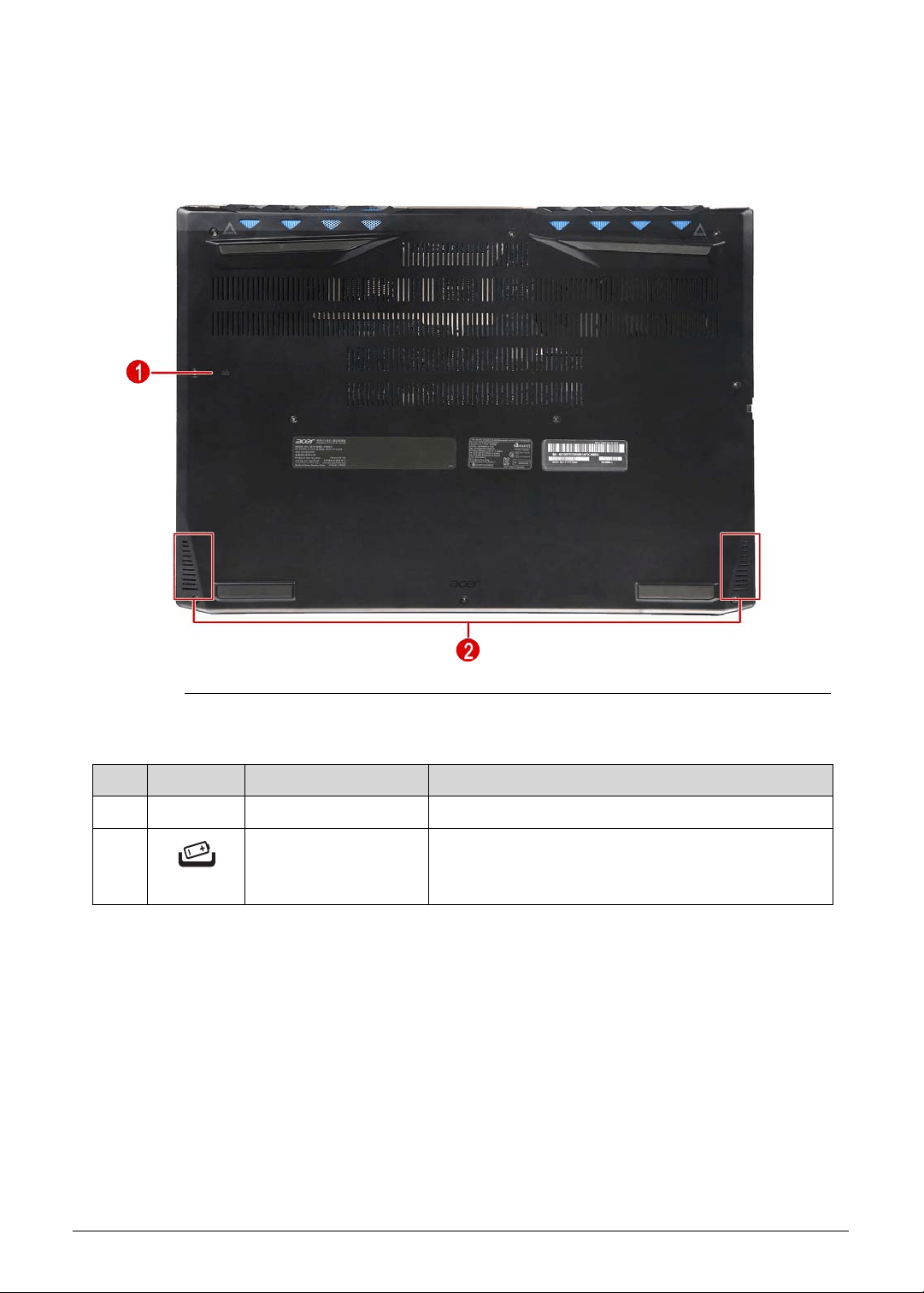
Base View 0
Figure 1-4. Base View
Table 1-4. Base View
No. Icon Item Description
1 Speaker Outputs sounds.
2 Battery reset pinhole Insert a paperclip into the hole and press for four
seconds to reset the computer (simulates removing
and reinstalling the battery).
Hardware Specifications and Configurations 1-15
Touchpad Basics 0
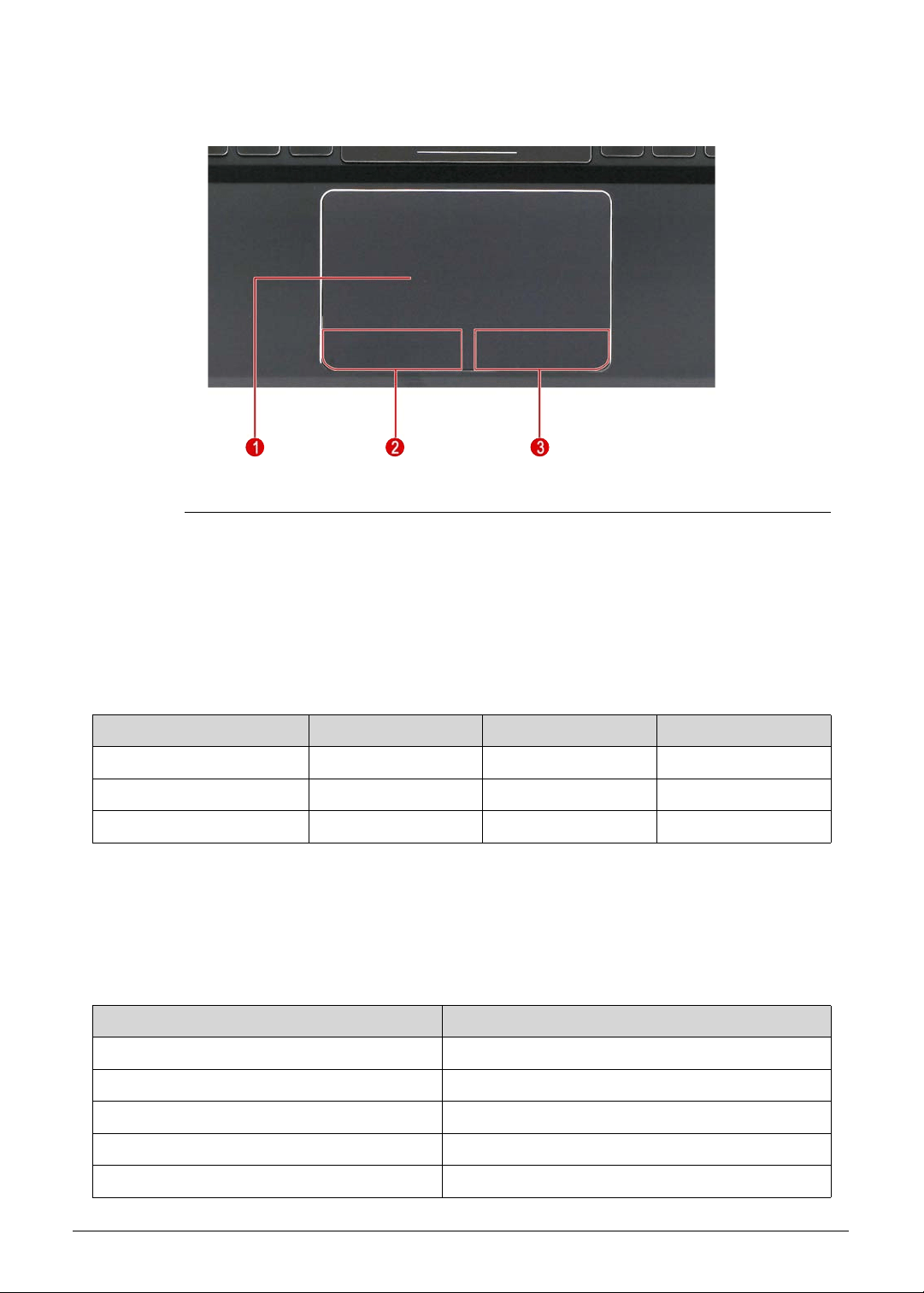
Figure 1-5. Touchpad
Move finger across the touchpad (1) to move the cursor. Tapping on the touchpad is the
same as clicking the left button of a mouse.
Press the left (2) and right (3) buttons located beneath the touchpad to perform
selection and execution functions. These two buttons are the equivalent of the left and
right buttons on a mouse.
Touchpad Gestures 0
Windows 10 and many applications support touchpad gestures that use one or more fingers.
Note: Support for touchpad gestures depends on the active application.
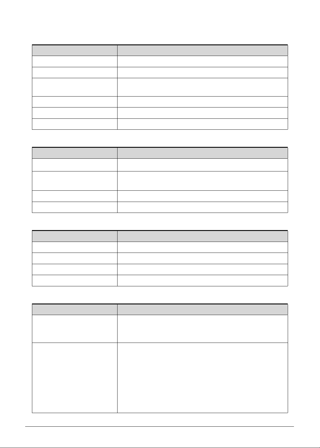
Table 1-5. Touchpad Basics
Function Touchpad (1) Left Button (2) Right Button (3)
Execute Rapidly tap twice. Quickly click twice.
Select Tap once. Click once.
Access context menu Click once.
Table 1-6. Touchpad Gestures
Function Gesture
Toggle the charms Swipe in from right edge.
Toggle the app commands Swipe in from top edge.
Switch to previous app Swipe in from left edge.
Fast scroll Two-finger slide.
Zoom in/out Two-finger pinch
1-16 Hardware Specifications and Configurations
Keyboard 0
The keyboard contains an overlay numeric keys, inverted “T” cursor key, Windows® key,
Application key, function lock keys, and hotkeys controlling various computer features.
Figure 1-6. Keyboard
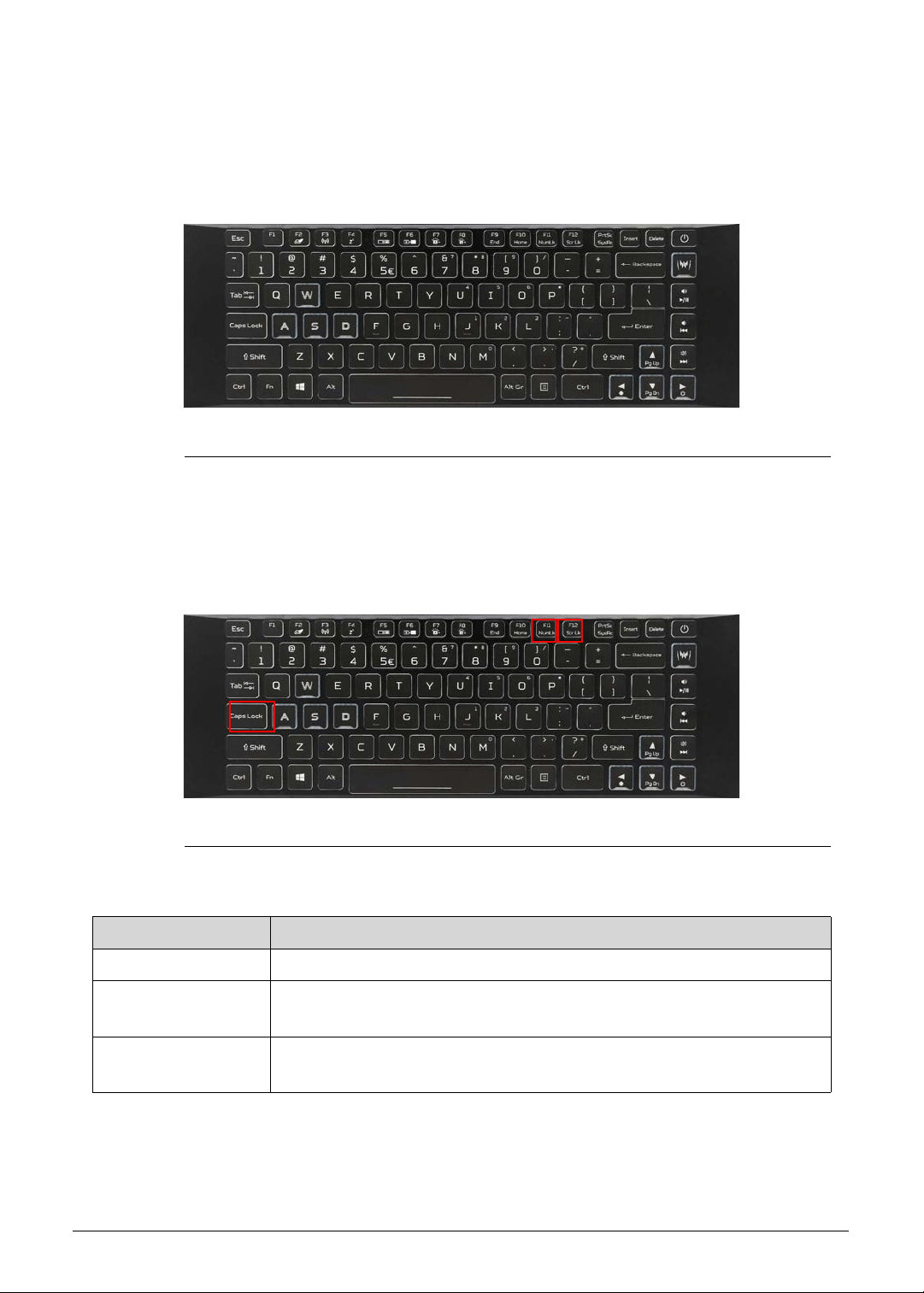
Lock Keys 0
The keyboard has three lock keys which the user can toggle on and off.
Figure 1-7. Keyboard Lock Keys
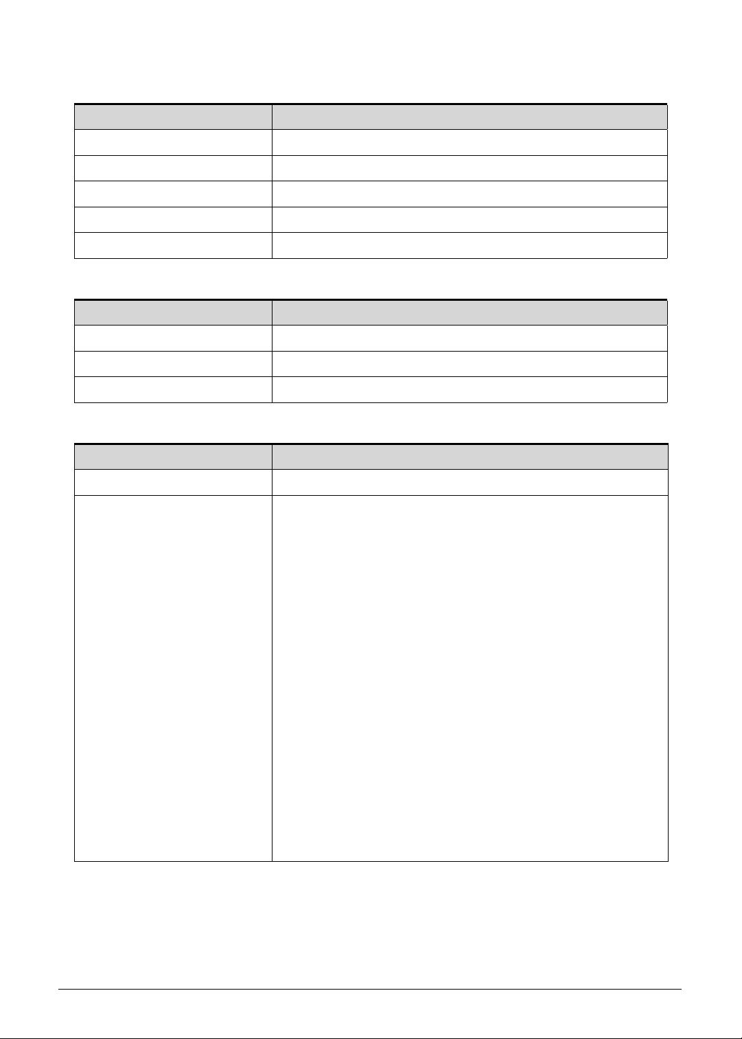
Table 1-7. Keyboard Lock Keys
Lock Key Description
Caps Lock When On, all typed alphabetic characters appears in uppercase.
Num Lock
Fn+F11
Off by default. When On, the overlay numeric keypad function is
activated.
Scroll Lock
Fn+F12
When On, the screen moves one line up or down when pressing the up
or down cursor keys. Scroll Lock is not applicable for all applications.
Hardware Specifications and Configurations 1-17
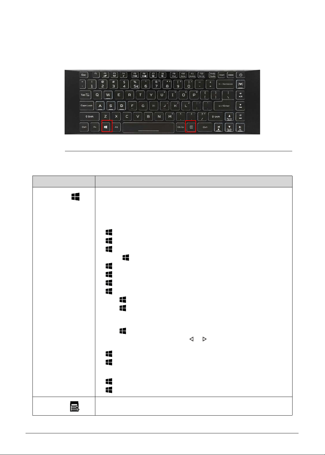
Windows Keys 0
The keyboard has two keys that perform Windows-specific functions.
Figure 1-8. Windows-specific Keys
Table 1-8. Windows-specific Keys
Key Description
Windows
Logo key
Pressed alone, this key has the same effect as clicking on the Windows
Start button; it launches the Start menu. It can also be used with other
keys to provide a variety of functions.
Functions supported by Windows XP, Windows Vista, Windows 7 and
Windows 8:
: Toggle the screen between desktop and Start screen
+R: Open the Run dialog box
+M: Minimizes all windows
Shift++M: Restore minimized windows to the desktop
+F1: Show the Help window
+ E: Open Windows Explorer
+F: Search for a file or folder
+ D: Display the desktop
Ctrl++F: Search for computers (if you are on a network)
Ctrl++L: Lock your computer (if you are connected to a network
domain), or switch users (if you're not connected to a network
domain)
Ctrl++Tab: Moves focus from Start menu, to the Quick Launch
toolbar, to the system tray (use or to move focus to items on the
Quick Launch toolbar and the system tray)
+Tab: Cycle through programs on the taskbar
+Break: Display the System Properties dialog box
Functions supported by Windows XP:
+Break: Display the System Properties dialog box
+U: Open the Ease of Access Center window
Application
key
This key has the same effect as clicking the right mouse button; it opens
the application's context menu.
1-18 Hardware Specifications and Configurations
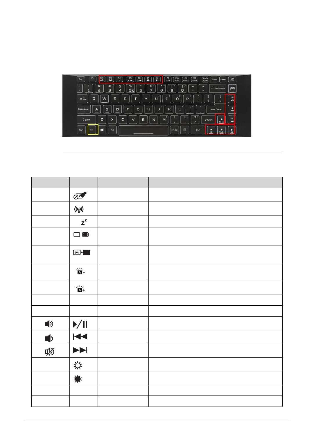
Hotkeys 0
The computer uses hotkeys or key combinations to access most computer controls. To
activate hotkeys, press and hold the Fn key before pressing the key in the combination.
Figure 1-9. Hotkeys
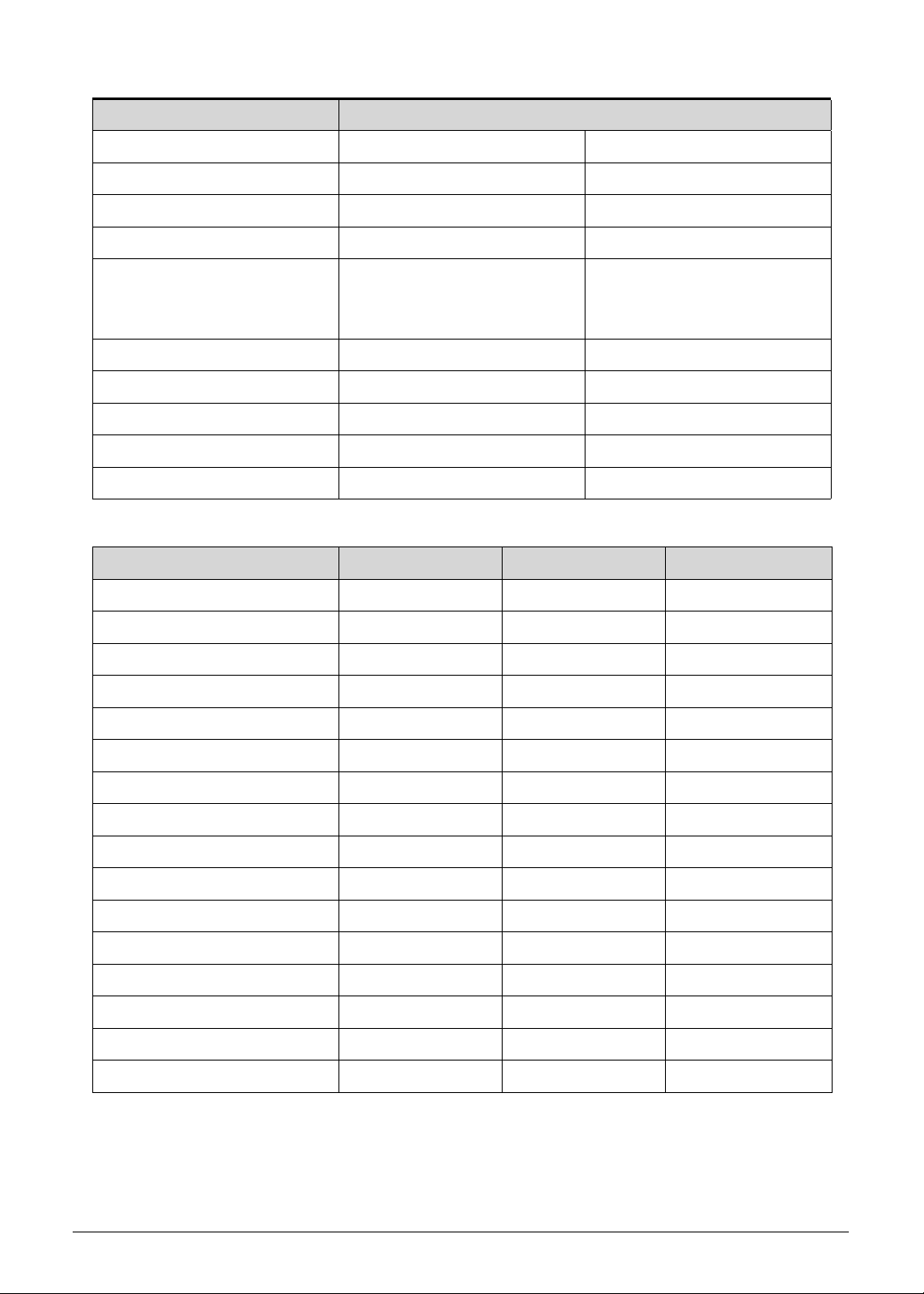
Table 1-9. Hotkeys
Hotkey Icon Function Description
Fn+F2 Touchpad toggle Turns the internal touchpad on and off.
Fn+F3 Airplane mode Turns on / off the computer's network devices.
Fn+F4 Sleep Puts the computer in Sleep mode.
Fn+F5 Display toggle Switches the display output between the display
screen, external monitor (if connected) or both.
Fn+F6 Display off Turns the display screen backlight off to save
power. Press any key to return.
Fn+F7 KB Brightness
down
Decreases the keyboard backlight brightness.
Fn+F8 KB Brightness up Increases the keyboard backlight brightness.
Fn+F9 End End Scrolls to the end of the document.
Fn+F10 Home Home Scrolls to the beginning of a document.
Fn+ Play/Pause Play or pause a selected media file.
Fn+ Previous Return to the previous media file.
Fn+ Next Jump to the next media file.
Fn+► Brightness up Increases the screen brightness.
Fn+◄ Brightness down Decreases the screen brightness.
Fn+▲ Pg Up Page Up Scrolls up a page in a document.
Fn+▼ Pg Dn Page Down Scrolls down a page in a document.
Hardware Specifications and Configurations 1-19
D2D Recovery 0
The Disk to Disk (D2D) recovery function allows you to use the recovery partition to
troubleshoot your computer.
1. Restart the computer.
2. During POST, press F2 to access the BIOS Setup screen.
3. Select the Main menu.
4. Select the D2D Recovery field and make sure it is set to Enabled.
5. Press F10 to save settings and close the BIOS Setup screen.
6. During POST, press Alt+F10 to enter the system recovery partition. This will display the
eRecovery Management window.
7. Follow the onscreen instructions to return your computer to factory condition.
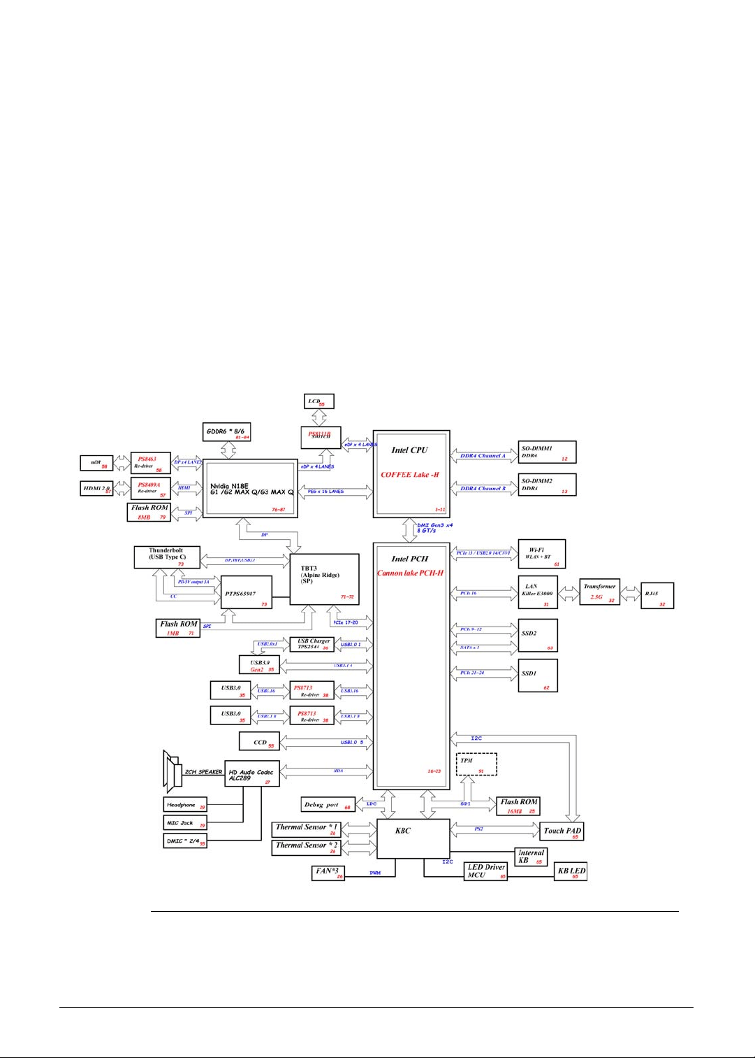
System Block Diagram 0
Figure 1-10. System Block Diagram
1-20 Hardware Specifications and Configurations
Specification Tables 0
Computer Specifications
Item Metric Imperial
Dimensions
Width 35.85 cm 14.11 in
Depth 25.50 cm 10.04 in
Height 1.79 cm 0.7 in
Weight (equipped with 4-cell
battery pack)
2.1 kg 4.63 lbs
Input power
Operating voltage 19.5 V
Operating current (max) 8.25 A
Temperature
Operating (not writing to
optical disc)
0 to +40 °C 32 to +104 °F
Operating (writing to optical
disc)
0 to +40 °C 32 to +104 °F
Nonoperating -20 to +60 °C -4 to +140 °F
Relative humidity
Operating 0% to 80%
Nonoperating 0% to 80%
Maximum altitude (unpressurized)
Operating N/A N/A
Nonoperating N/A N/A
Shock
Operating 105 g, 2 ms, half-sine 3.7 lbs, 0.002 s, half-sine
Nonoperating 220 g, 2 ms, half-sine 7.76 lbs, 0.002 s, half-sine
Random vibration
Operating 0.6 g zero-to-peak, 5 to 500 Hz, random wave, 30 min
Nonoperating 1.5 g zero-to-peak, 5 to 500 Hz, random wave, 30 min
Applicable product safety standards specify thermal limits for plastic surfaces. The computer
operates well within this range of temperatures.
Hardware Specifications and Configurations 1-21
System Board
Processor
Processor Specifications
CPU Fan True Value Table
Item Specification
Core logic
Intel
®
Coffee Lake H Platform
Graphics
NVIDIA
®
GeForce
®
RTX 2080M
NVIDIA
®
GeForce
®
RTX 2070M
NVIDIA
®
GeForce
®
RTX 2060M
Intel
®
HD Graphics
LAN Killer™ LAN E3000
USB 2.0/3.0
Integrated in the Mobile Intel
®
HM370 Express Chipset
Wireless LAN + BT Killer™ Wireless-AC 1550 / 1550i
Audio codec Realtek ALC289
Item Specification
CPU type
8th Generation Intel
®
Core™ Mobile Processor (Coffee Lake)
Core logic L1 cache size
6 x 32 KB 8-way set associative instruction caches
6 x 32 KB 8-way set associative data caches
L2 cache size
6 x 256 KB 4-way set associative caches
L3 cache size
9 MB 12-way set associative shared cache
Item CPU
Speed
Cores/
Threads
Max Turbo
Freq
Mfg
Tech
L3
Cache
Max
TDP
i7-8750H 2.2 GHz 6C/12T 4.1 GHz 14 nm 9 MB 45 W
i5-8300H 2.3 GHz 4C/8T 4.0 GHz 14 nm 8 MB 45 W
CPU
Temperature
CPU Fan Speed
(RPM)
GPU2 Fan
Speed (RPM)
GPU1 Fan
Speed (RPM)
SPL Spec
(dBA)
45 2100 2500 2100 22
51 2300 2800 2400 25
57 2600 3100 2600 28
64 2900 3400 2900 31
71 3100 3800 3300 34
1-22 Hardware Specifications and Configurations
GPU Fan True Value Table
System Memory
78 3000 4300 4100 37
85 3200 4700 4600 40
90 3400 5300 5100 43
Throttling 50%: On = 99° C; Off = 85° C
OS shuts down at 100° C; Hardware shuts down at 100° C
CPU
Temperature
CPU Fan Speed
(RPM)
GPU2 Fan
Speed (RPM)
GPU1 Fan
Speed (RPM)
SPL Spec
(dBA)
x 2100 2500 2100 46
x 2300 2800 2400 49
x 2600 3100 2600 52
x 2900 3400 2900 55
x 3100 3800 3300 58
65 3000 4300 4100 61
73 3200 4700 4600 64
79 3400 5300 5100 67
Throttling 50%: On = 99° C; Off = 85° C
OS shuts down at 100° C; Hardware shuts down at 100° C
Item Specification
Memory controller
Integrated in the Intel
®
Core™ Mobile Processor (Coffee Lake)
Memory size 8 or 16 GB
Number of DIMM socket 2
Maximum memory size per
socket
16 GB
Maximum system memory
size
32 GB
DIMM type DDR4 SDRAM
DIMM speed 2666 MHz
DIMM voltage 1.2 V
DIMM package 204-pin SO-DIMM
CPU
Temperature
CPU Fan Speed
(RPM)
GPU2 Fan
Speed (RPM)
GPU1 Fan
Speed (RPM)
SPL Spec
(dBA)
Hardware Specifications and Configurations 1-23
Memory Combinations
Graphics Controller
System BIOS
Slot 1 (MB) Slot 2 (MB) Total Memory (MB)
8192 N/A 8192
8192 8192 16384
8192 16384 24576
16384 N/A 16384
16384 16384 32768
Item Specification
Chipset
NVIDIA
®
GeForce
®
RTX 2080 / 2070 with 8 GB of dedicated
GDDR6 VRAM or NVIDIA
®
GeForce
®
RTX 2060 with 6 GB of
dedicated GDDR6 VRAM
Item Specification
BIOS vendor Insyde Software
BIOS version v 1.00
BIOS ROM type Hardware
BIOS ROM size 8 MB
Protocols supported
Legacy BIOS and EFI BIOS architecture support
PXE specification v2.1 or later
SMBIOS reference specification v3.0 or later
USB specification revision 1.1/2.0/3.0 v3.0 or later
ASF specification v2.0 or later
PCI/PCI Express base specification revision 3.0 or later
PCI BIOS specification revision 3.0 or later
BIOS Boot specification v1.01 or later
Simple boot flag specification v2.1 or later
System management bus specification v2.0 or later
AHCI support
Microsoft XP/Vista/Windows 7/8/10 logo program
Microsoft SLP 1.0 support
Microsoft OA 2.0 and 2.1 support
ACPI specification 5.0 or later
UEFI specification 2.6 or later
Intel V-pro implementation
AMD Virtualization technology support
Nvidia Optimus enabled
1-24 Hardware Specifications and Configurations
Keyboard
Solid State Drive (SSD)
LCD Panel
Item Specification
Type Acer FineTip™ RGB backlit keyboard
Total number of keys
86-/87-/90-keys
Windows logo key Yes
Internal and external USB
keyboard work
simultaneously?
Yes
Features
Hotkeys for volume and brightness level, wireless and sleep
functions, and display and touchpad toggle
Windows
®
and Application keys
Inverted “T” cursor keys
Turbo key and power button key
Multilanguage support
Item Specification
Vendor and models Qimonda F80256PMP,
SANDISK
SDAPNTW-256G-1014
Qimonda F80512PMP,
SANDISK
SDAPNTW-512G-1014
Configuration
Form Factor M.2 2280
Interface PCIe Gen 3 x4 NVMe v1.3
Capacity (GB)
256 512
Performance
Max. Read Speed 3000 MB / s 3400 MB / s
Max. Write Speed 1600 MB / s 2400 MB / s
Power
Requirement 3.3 VDC
Item Specification
Vendor and models AUO B156HAN08.2 BOE NV156FHM-N4K
Screen size (diagonal) 15.6W” (15.547”) 15.6W” (15.547”)
Active area 344.16 X193.59 mm 344.16 X193.59 mm
Display resolution (pixels) 1920×1080 (FHD) 1920×1080 (FHD)
Pixel pitch 0.17925×0.17925 mm 0.17925×0.17925 mm
Hardware Specifications and Configurations 1-25
Supported GPU Resolutions
Viewing angle (H/V) 85/85/85/85 89/89/89/89
Brightness 300 nit 300 nit
Surface Antiglare Antiglare (Haze 25%)
Contrast ratio 800:1 1200:1
Response time
Typical
Maximum
9ms
13 ms
9ms
12 ms
Typical power consumption 8.5 W max. 7.7 W max.
Electrical interface eDP (4 Lanes) eDP (4 Lanes)
Backlight WLED WLED
Weight 310 g Max 300 g Max
Physical size 350.66 × 216.156 × 2.8 350.66 × 215.25 × 2.6 mm
Resolution 64 bits Intel NV
800 x 600, 144Hz 4:3 v v v
1024 x 768, 144Hz 4:3 v v v
1152 x 864, 144Hz 4:3 v v v
1280 x 600, 144Hz 32:15 v v v
1280 x 720, 144Hz 16:9 v v v
1280 x 768, 144Hz 5:3 v v v
1280 x 800, 144Hz 8:5 v v v
1280 x 960, 144Hz 4:3 v v v
1280 x 1024, 144Hz 5:4 v v v
1360 x 768, 144Hz 85:48 v v v
1366 x 768, 144Hz 16:9 v v v
1400 x 1050, 144Hz 4:3 v v v
1440 x 900, 144Hz 8:5 v v v
1600 x 900, 144Hz 16:9 v v v
1680 x 1050, 144Hz 8:5 v v v
1920 x 1080, 144Hz 16:9 v v v
Item Specification
1-26 Hardware Specifications and Configurations
Supported Display Resolutions
Audio Codec
Resolution 64 bits Intel NV
720 x 480, 144Hz 3:2 — — v
800 x 600, 144Hz 4:3 v v v
1024 x 768, 144Hz 4:3 v v v
1152 x 864, 144Hz 4:3 v v v
1280 x 600, 144Hz 32:15 v v v
1280 x 720, 144Hz 16:9 v v v
1280 x 768, 144Hz 5:3 v v v
1280 x 800, 144Hz 8:5 v v v
1280 x 960, 144Hz 4:3 v v v
1280 x 1024, 144Hz 5:4 v v v
1360 x 768, 144Hz 85:48 v v v
1366 x 768, 144Hz 16:9 v v v
1400 x 1050, 144Hz 4:3 v v v
1440 x 900, 144Hz 8:5 v v v
1600 x 900, 144Hz 16:9 v v v
1600 x1024, 144Hz 25:16 — — v
1600 x1200, 144Hz 4:3 — — v
1680 x 1050, 144Hz 8:5 v v v
1920 x 1080, 144Hz 16:9 v v v
Item Specification
Controller Realtek ALC289
Features
Supports PCBEEP pass-through to Class-D output,
headphone amplifier and Class-D speaker amplifier
Sound pressure level protection against excursion damage
or temperature damage
AGC (Auto Gain Control) function for Class-D amplifier
removes distortion when outputting high volume sound
SPDIF-OUT supports 16/20/24-bit format and
44.1/48/88.2/96/192 kHz sample rate
48-pin 6x6 mm MQFN “Green” package
Hardware Specifications and Configurations 1-27
Audio Interface
Webcam
LAN
Item Specification
Controller Realtek ALC289
Audio onboard Yes
Audio channel Stereo
Resolution 16/20/24 bit stereo full duplex
Compatibility High Definition Audio Specification
Sampling rate 192 kHz resolution VSR (Variable Sampling Rate)
Internal microphone Yes, digital microphone
Internal speaker/quantity Yes, two speakers
Item Specification
Vendor and models
LITEON HD Camera 7BF115N2
CHICONY HD Camera CH_OV9734_RTS5846W
Resolution 1.0 MP HD
Item Specification
LAN controller Killer™ Ethernet E3000
LAN connector type RJ-45
LAN connector location One (left)
Features
Integrated 10/100/1000Mbps/2.5Gbps transceiver
Compatible with 2.5GBASE-T Alliance PHY Specification
Supports 2.5 Gbps with Cat 5e and above
IPv4 and IPv6 support
Supports jumbo frame to 16K bytes
RSS support
Supports Wake Up Frame or Magic Packet
Supports APCI, PCI MSI, and MSI-X
Compliant with Microsoft NDIS5, NDIS6 (IPv4, IPv6, TCP,
UDP) Checksum and
Segmentation Task-offload features
Supports IEEE 802.1P Layer 2 Priority Encoding
IEEE 802.1Q VLAN support
IEEE 802.1p QoS support
Supports PCIe L1 substate L1.1and L1.2
Features inter-connect PCI Express technology
Supports connected standby
Supports IEEE 802.3az-2010 (Energy Efficient Ethernet)
1-28 Hardware Specifications and Configurations
Wireless LAN
USB Interface
HDMI Port
System LED Indicators
Item Specification
Module Killer™ Wireless-AC 1550 / 1550i
Frequency band Dual Band (2.4 GHz and 5 GHz)
Protocols and data rates
supported
802.11a/b/g/n/ac
Interface PCI Express
Form factor M.2 (NGFF) mini PCIe card type
Antennae Dual MHF4 Antenna Connectors
Item Specification
Controller
Integrated in the Mobile Intel
®
HM370 Express Chipset
Number and location of USB
port
USB 3.1 Gen 1 – Three (2 on right side and 1 on left side)
USB 3.1 Gen 2 (Type-C) – One (right side)
EHCI 2
Output current 1.0A for each connector
Item Specification
Compliance level HDMI 2.0
Data throughput Up to 68.7 billion colors (4K 12-bit colour depth)
Number of HDMI port One
Location Left
Item Specification
Power status
Solid blue: The computer is turned on.
Blinking amber: The computer is in power-saving mode.
Indicator off: The computer is turned off.
Battery status AC adapter connected:
Solid blue: The battery charge is at full capacity.
Solid amber: Battery charging.
Blinking amber: Battery is in abnormal stop charge or battery
is in low power state.
AC adapter disconnected:
Blinking amber: Battery charge is in critically low state
Indicator off: Discharging state.
Hardware Specifications and Configurations 1-29
Battery Pack
AC Adapter
System Power Management
Item Specification
Vendor and models Getac AP18J
Battery type Lithium-polymer
Pack capacity 5550 mAh
Number of battery cell 4
Package configuration 4S1P
Item Specification
Input rating 180 W
Input AC current (max) 100-240 V, 2.5 A, 50-60 Hz
Output 19.5 V, 3-pin
Item Specification
Power management system ACPI 3.0-compliant
Power global states
G3 Mechanical Off - This off state is entered through a
mechanical means; no electrical current is running through
the circuitry and it can be worked on without damaging the
hardware or endangering service personnel. Except for the
real-time clock, power consumption is zero.
G2/S5 Soft Off - OS initiated shutdown. The computer
consumes a minimal amount of power. No user mode or
system mode code is run. It is not safe to disassemble the
machine in this state.
G1 Sleeping - The computer consumes a small amount of
power, user mode threads are not being executed, and the
system “appears” to be off. It is not safe to disassemble the
machine in this state
G0 Working - The computer dispatches user mode
(application) threads and they execute. It is not safe to
disassemble the machine in this state.
S4 Non-Volatile Sleep - Also known as hibernation state. A
special global system state that allows system context to be
saved and restored (relatively slowly) when power is lost to
the mainboard. It is not safe to disassemble the machine in
this state.

1-30 Hardware Specifications and Configurations
System Interrupt Specification
Resource Device
(ISA) 0x00000000 (00) System timer
(ISA) 0x00000001 (01) Standard PS/2 Keyboard
(ISA) 0x00000008 (08) System CMOS/real time clock
(ISA) 0x00000013 (13) Numeric data proccessor
(ISA) 0x0000000E (14) Intel(R) Serial IO GPIO Host Controller - INT3450
(ISA) 0x00000036 (54) ~
(ISA) 0x00000059 (89)
Microsoft ACPI-Compliant System
(ISA) 0x0000005A (90) I2C HID Device
(ISA) 0x0000005A (90) ~
(ISA) 0x000000CC (204)
Microsoft ACPI-Compliant System
(ISA) 0x00000100 (256) ~
(ISA) 0x000001FF (511)
Microsoft ACPI-Compliant System
(PCI) 0x00000010 (16) High Definition Audio Controller
(PCI) 0x00000010 (16) Intel(R) Dynamic Platform and Thernal Framework Processor
Participant
(PCI) 0x00000010 (16) Intel(R) Serial IO I2C Host Controller - A368
(PCI) 0x00000011 (17) High Definition Audio Controller
(PCI) 0x00000011 (17) Intel(R) Serial IO I2C Host Controller - A369
(PCI) 0xFFFFFFAD (-83) NVDIA GeForce RTX 2070
(PCI) 0xFFFFFFAE (-82) Intel(R) Management Engine Interface
(PCI) 0xFFFFFFAF (-81) ~
(PCI) 0xFFFFFFB2 (-78)
Killer E3000 2.5 Gigabit Ethernet Controller
(PCI) 0xFFFFFFB3 (-77) Killer(R) Wireless-AC 1550i Wireless Network Adapter
(9560NGW) 160MHz
(PCI) 0xFFFFFFB4 (-76) Killer(R) Wireless-AC 1550i Wireless Network Adapter
(9560NGW) 160MHz
(PCI) 0xFFFFFFB5 (-75) Intel(R) USB 3.1 eXtensible Host Controller - 1.10 (Microsoft)
(PCI) 0xFFFFFFB6 (-74) Intel(R) UHD Graphics 630
(PCI) 0xFFFFFFB7 (-73) NVDIA USB Type-C Port Policy Controller
(PCI) 0xFFFFFFB8 (-72) NVDIA USB 3.10 eXtensible Host Controller - 1.10(Microsoft)
(PCI) 0xFFFFFFB9 (-71) ~
(PCI) 0xFFFFFFFA (-6)
Intel(R) Chipset SATA/PCIe RST Premium Controller
(PCI) 0xFFFFFFFB (-5) Intel(R) PCI Express Root Port #9 - A330
(PCI) 0xFFFFFFFC (-4) Intel(R) PCI Express Root Port #16 - A337
(PCI) 0xFFFFFFFD (-3) Intel(R) PCI Express Root Port #17 - A340

Hardware Specifications and Configurations 1-31
System IO Address Map
(PCI) 0xFFFFFFFE (-2) Intel(R) PCIe Controller (x16) - 1901
Resource Device
[0x00000000 - 0x00000CF7] PCI Express Root complex
[0x00000020 - 0x00000021] Programmable interrupt controller
[0x00000024 - 0x00000025] Programmable interrupt controller
[0x00000028 - 0x00000029] Programmable interrupt controller
[0x0000002C - 0x0000002D] Programmable interrupt controller
[0x0000002E - 0x0000002F] Motherboard resources
[0x00000030 - 0x00000031] Programmable interrupt controller
[0x00000034 - 0x00000035] Programmable interrupt controller
[0x00000038 - 0x00000039] Programmable interrupt controller
[0x0000003C - 0x0000003D] Programmable interrupt controller
[0x00000040 - 0x00000043] System timer
[0x0000004E - 0x0000004F] Motherboard resources
[0x00000050 - 0x00000053] System timer
[0x00000060 - 0x00000060] Standard PS/2 Keyboard
[0x00000061 - 0x00000061] Motherboard resources
[0x00000062 - 0x00000062] Microsoft ACPI-Compliant Embedded Controller
[0x00000063 - 0x00000063] Motherboard resources
[0x00000064 - 0x00000064] Standard PS/2 Keyboard
[0x00000065 - 0x00000065] Motherboard resources
[0x00000066 - 0x00000066] Microsoft ACPI-Compliant Embedded Controller
[0x00000067 - 0x00000067] Motherboard resources
[0x00000068 - 0x0000006F] Motherboard resources
[0x00000070 - 0x00000070] Motherboard resources
[0x00000070 - 0x00000077] System CMOS/real time clock
[0x00000080 - 0x00000080] Motherboard resources
[0x00000092 - 0x00000092] Motherboard resources
[0x000000A0 - 0x000000A1] Programmable interrupt controller
[0x000000A4 - 0x000000A5] Programmable interrupt controller
[0x000000A8 - 0x000000A9] Programmable interrupt controller
[0x000000AC - 0x000000AD] Programmable interrupt controller
Resource Device

1-32 Hardware Specifications and Configurations
[0x000000B0 - 0x000000B1] Programmable interrupt controller
[0x000000B2 - 0x000000B3] Motherboard resources
[0x000000B4 - 0x000000B5] Programmable interrupt controller
[0x000000B8 - 0x000000B9] Programmable interrupt controller
[0x000000BC - 0x000000BD] Programmable interrupt controller
[0x000000F0 - 0x000000F0] Numeric data processor
[0x000004D0 - 0x000004D1] Programmable interrupt controller
[0x00000D00 - 0x0000FFFF] PCI Express Root complex
[0x00001800 - 0x000018FE] Motherboard resources
[0x00001800 - 0x000018FE] Motherboard resources
[0x00001854 - 0x00001857] Intel(R) Watchdog Timer Driver (Intel(R) WDT)
[0x00002000 - 0x000020FF] Motherboard resources
[0x00003000 - 0x000030FF] Killer E3000 2.5 Gigabit Ethernet Controller
[0x00003000 - 0x000030FF] Intel(R) PCI Express Root Port #16 - A337
[0x00004000 - 0x00004FFF] Intel(R) PCIe Controller (x16) - 1901
[0x00005000 - 0x0000503F] Intel(R) UHD Graphics 630
[0x00005040 - 0x0000505F] Intel(R) SMBus - A323
[0x00005060 - 0x0000507F] Intel(R) Chipset SATA/PCIe RST Premium Controller
[0x00005080 - 0x00005087] Intel(R) Chipset SATA/PCIe RST Premium Controller
[0x00005088 - 0x00005088] Intel(R) Chipset SATA/PCIe RST Premium Controller
[0x0000FFFF - 0x0000FFFF] Motherboard resources
[0x0000FFFF - 0x0000FFFF] Motherboard resources
[0x0000FFFF - 0x0000FFFF] Motherboard resources
Resource Device

CHAPTER 2
System Utilities

2-2
BIOS Setup Utility . . . . . . . . . . . . . . . . . . . . . . . . . . . . . . . . . . . . .2-3
Navigating the BIOS Utility . . . . . . . . . . . . . . . . . . . . . . . . . . . .2-3
BIOS Menus . . . . . . . . . . . . . . . . . . . . . . . . . . . . . . . . . . . . . . . . . .2-4
Information. . . . . . . . . . . . . . . . . . . . . . . . . . . . . . . . . . . . . . . . .2-4
Main. . . . . . . . . . . . . . . . . . . . . . . . . . . . . . . . . . . . . . . . . . . . . .2-6
Security . . . . . . . . . . . . . . . . . . . . . . . . . . . . . . . . . . . . . . . . . . .2-8
Boot . . . . . . . . . . . . . . . . . . . . . . . . . . . . . . . . . . . . . . . . . . . . . .2-12
Exit. . . . . . . . . . . . . . . . . . . . . . . . . . . . . . . . . . . . . . . . . . . . . . .2-14
BIOS Flash Utilities . . . . . . . . . . . . . . . . . . . . . . . . . . . . . . . . . . . .2-15
Removing the HDD Password . . . . . . . . . . . . . . . . . . . . . . . . . . .2-16
Removing the HDD Password (DOS) . . . . . . . . . . . . . . . . . . . .2-16
Removing the HDD Password (Windows) . . . . . . . . . . . . . . . . .2-17
Removing BIOS Passwords . . . . . . . . . . . . . . . . . . . . . . . . . . . . .2-18
Removing the BIOS Passwords (Hardware Gap) . . . . . . . . . . .2-18
Removing the BIOS Passwords (Software). . . . . . . . . . . . . . . .2-19
Using DMI Utility . . . . . . . . . . . . . . . . . . . . . . . . . . . . . . . . . . . . . .2-22
Using DMI Utility . . . . . . . . . . . . . . . . . . . . . . . . . . . . . . . . . . . .2-22

System Utilities 2-3
System Utilities
This chapter lists the system utilities installed in the Predator Triton 515-51 computer.
BIOS Setup Utility 0
This utility is a hardware configuration program built into a computer’s BIOS (Basic
Input/Output System).
The utility is pre-configured and optimized so most users do not need to run it. If configuration
problems occur, the setup utility may need to be run. Refer to Chapter 4, Troubleshooting
when a problem arises.
To enter this utility, during POST (power-on self-test) press
F2.
The default setting of the F12 Boot Menu is Disabled. To change the boot device without
entering the BIOS Setup Utility, set the parameter to Enabled. During the next POST, press
F12 to enter the multi-boot menu.
Navigating the BIOS Utility 0
The BIOS Setup Utility has five menu options, namely:
Information
Main
Advanced
Security
Boot
Exit
Perform the following actions to navigate through the BIOS Setup Utility:
Press to select items in the menu bar.
Press to select an item in the menu screen or in an option box.
Press F5 or F6 to change the parameter value.
Press Esc to exit from the Setup Utility.
Press F9 to load the default settings.
Press F10 to save changes and exit from the Setup Utility.
NOTE:
NOTE:
Parameter values enclosed in square brackets [ ] can be change. Navigation
keys appear on the bottom of the screen. Read the item specific help on the
right area of the screen before making changes to the parameter values.
NOTE:
NOTE:
System information can vary depending on the computer model.
2-4 System Utilities
BIOS Menus 0
This section describes the InsydeH20 BIOS Setup Utility menu tabs.
NOTE:
NOTE:
The screenshots used in this chapter are for reference only. Actual values can
vary depending on the computer model.
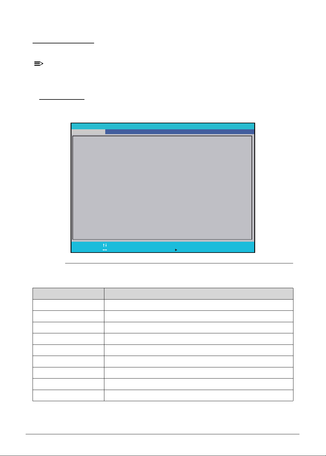
Information 0
This tab shows a summary of the computer‘s hardware information.
Figure 2-1. Hardware Information
Table 2-1. Hardware Information
Parameter Description
CPU Type Model name and core frequency of the installed processor
CPU Speed Core frequency of the installed processor
System BIOS Version Current system BIOS version
GOP Version Current GOP version of the system
HDD Model Name Model name of the installed hard drive
HDD Serial Number Serial number of the installed hard drive
ATAPI Model Name Model name of the installed optical device
Total Memory Total system memory available
Serial Number Serial number of the computer
InsydeH20 Setup Utility
CPU Type:
HDD0 Model Name:
HDD0 Serial Number:
HDD1 Model Name:
HDD1 Serial Number:
SATA Mode:
Total Memory:
Serial Number:
Asset Tag Number:
Product Name:
Manufacturer Name:
UUID:
System BIOS Version:
GOP Version:
F1
Esc
Help
Exit
Select Item
Select Menu
Change Values
Select Sub-Menu
F5/F6
Enter
F9
F10
Setup Defaults
S a v e a n d E x i t
Intel®
1.00
Intel(R) GOP Driver [9.0.1082]
XXXXXXXXXXXXXX
XXXXXXXXXXXXXX
XXXXXXXXXXXXXX
XXXXXXXXXXXXXX
Core(TM) i7-8750H CPU @ 2.2
XXXXXXXXXXXXXX
RST Premium with Optane
32768 MB
XXXXXXXXXXXXXXXXXXXXXXX
Predator PT515-51
Acer
XXXXXXXX-XXXX-XXXX-XXXX-XXXXXXXXXXX
0 G H z
Security Boot ExitMainInformation Advanced

System Utilities 2-5
Asset Tag Number Asset tag number of the computer
Product Name Model name of the computer
Manufacturer Name Computer manufacturer
UUID The universally unique identifier tag assigned to the computer
Table 2-1. Hardware Information (Continued)
Parameter Description
2-6 System Utilities
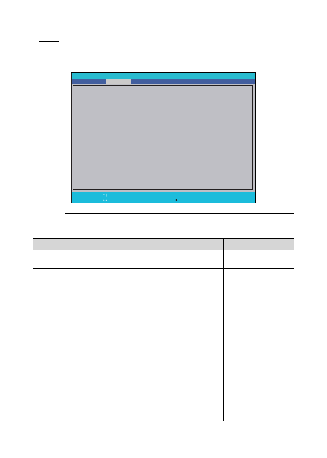
Main 0
Use this tab to set the system time and date, enable or disable boot options, and select
graphic mode.
Figure 2-2. BIOS Main
Table 2-2. BIOS Main
Parameter Description Format/Option
System Time System time expressed in 24-hour format. Format: HH:MM:SS
(hour:minute:second)
System Date System date. Format: MM/DD/YYYY
(month/day/year)
Network Boot Option to boot system from LAN. Enabled or Disabled
F12 Boot Menu Option to enter the Boot menu during POST. Enabled or Disabled
SATA Mode Option to set the SATA configuration.
When set to AHCI mode, the SATA controller
enables its AHCI functionality.
Set to RST with Optane if the system is Intel
Optane memory ready.
Set to RST Premium with Optane when you
want to create a RAID array.
Note: Applicable for system that supports Intel
Optane memory solution.
AHCI or RST with
Optane
Wake on LAN Option to wake up the system from a power
saving mode using LAN.
Enabled or Disabled
TBT Wake Option to enable S3 wake capability of
thunderbolt devices.
Enabled or Disabled
F1
Esc
Help
Exit
Select Item
Select Menu
Change Values
Select Sub-Menu
F5/F6
Enter
F9
F10
Setup Defaults
S a v e a n d E x i t
Item Specific Help
Hour Valid range is from
0 to 23. Minute Valid
range is from 0 to 59.
Second Valid range is
from 0 to 59. REDUCE/
INCREASE : F5/F6.
System Time:
System Date:
Network Boot:
F12 Boot Menu:
SATA Mode:
Wa k e o n L A N :
TBT Wake:
TBT Wake from S4 Support
USB Wake from S4 Support
Function key behavior:
L i d O p e n R e s u m e :
Wake on USB while lid closed
D2D Recovery:
Post Animation and Sound
F a s t B o o t
[]
[]
:05:48
01/15/2019
[Disabled]
[RST with Optane]
[Disabled]
[Enabled]
[Disabled]
[Disabled]
[Function Key]
[Enabled]
[Disabled]
[Disabled]
[Enabled]
10
[Enabled]
[Enabled]
Information Security Boot ExitMain Advanced
InsydeH20 Setup Utility

System Utilities 2-7
TBT Wake from S4
Support
Option to allow wake capability from S4 of
thunderbolt devices.
Enabled or Disabled
USB Wake from S4
Support
Option to allow USB wake from S4. Enabled or Disabled
Function key Option to set the Function key to perform
special function or activate the F1 to F12 keys.
Special keys or
Function keys
Lid Open Resume Option to enable system to automatically
resume after opening the display panel.
Enabled or Disabled
Wake on USB while
lid closed
Option to allow USB devices to wake the
system, even if the lid is closed.
Enabled or Disabled
D2D Recovery Option to enable disc-to-disc system recovery
feature
Enabled or Disabled
POST Animation &
Sound
Option to enable POST animation sound
effect.
Enabled or Disabled
Fast Boot Option to enable fast boot capability. Enabled or Disabled
Table 2-2. BIOS Main (Continued)
Parameter Description Format/Option
2-8 System Utilities
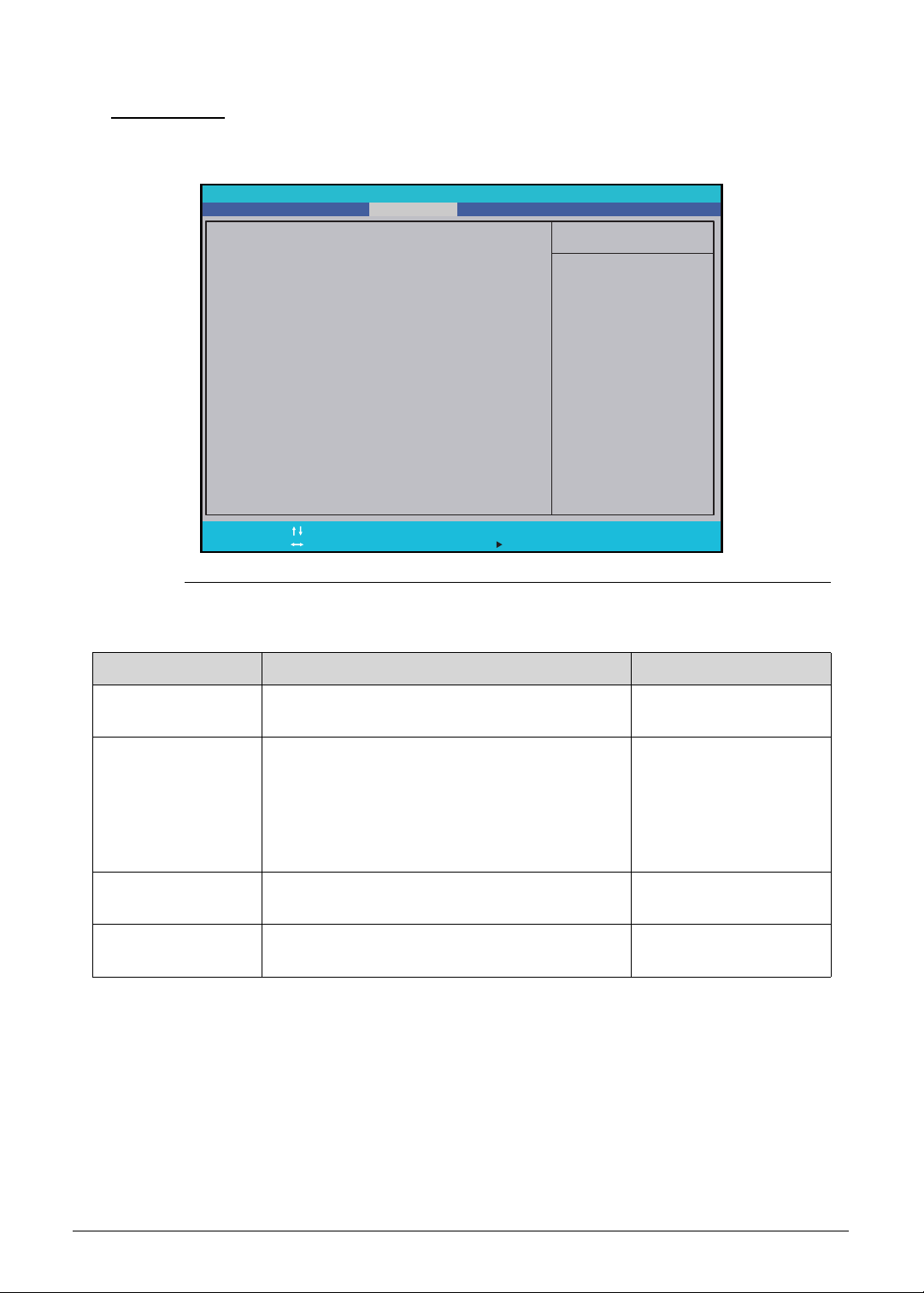
Advanced 0
Use this tab to enable Virtualization Technology in BIOS and configure Graphic mode.
Figure 2-3. BIOS Advanced
Table 2-3. BIOS Advanced
Parameter Description Format/Option
Intel VTX Option to enable the Intel Virtualization
Technology.
Enabled or Disabled
Intel VTD Option to enable the Intel Virtualization
Technology for directed I/O. VT-d allows a
LAN card to be dedicated to a guest system,
which makes attainment of increased network
performance beyond that of an emulated LAN
card possible.
Enabled or Disabled
TBT Detection Gain Option to enable support for multiple layer
thunderbolt devices detection.
Enabled or Disabled
Graphic mode Option to select graphic mode. MSHybrid or dGPU
only
Item Specific Help
T h i s i s I n t e l V T X f u n c t i o n
switch.
Intel VTX:
Intel VTD:
TBT Detection Gain:
Graphic mode:
F1
Esc
Help
Exit
Select Item
Select Menu
Change Values
Select Sub-Menu
F5/F6
Enter
F9
F10
Setup Defaults
S a v e a n d E x i t
[Enabled]
[Enabled]
[Disabled]
[dGPU only]
MainInformation
InsydeH20 Setup Utility
Security Boot ExitAdvanced
System Utilities 2-9
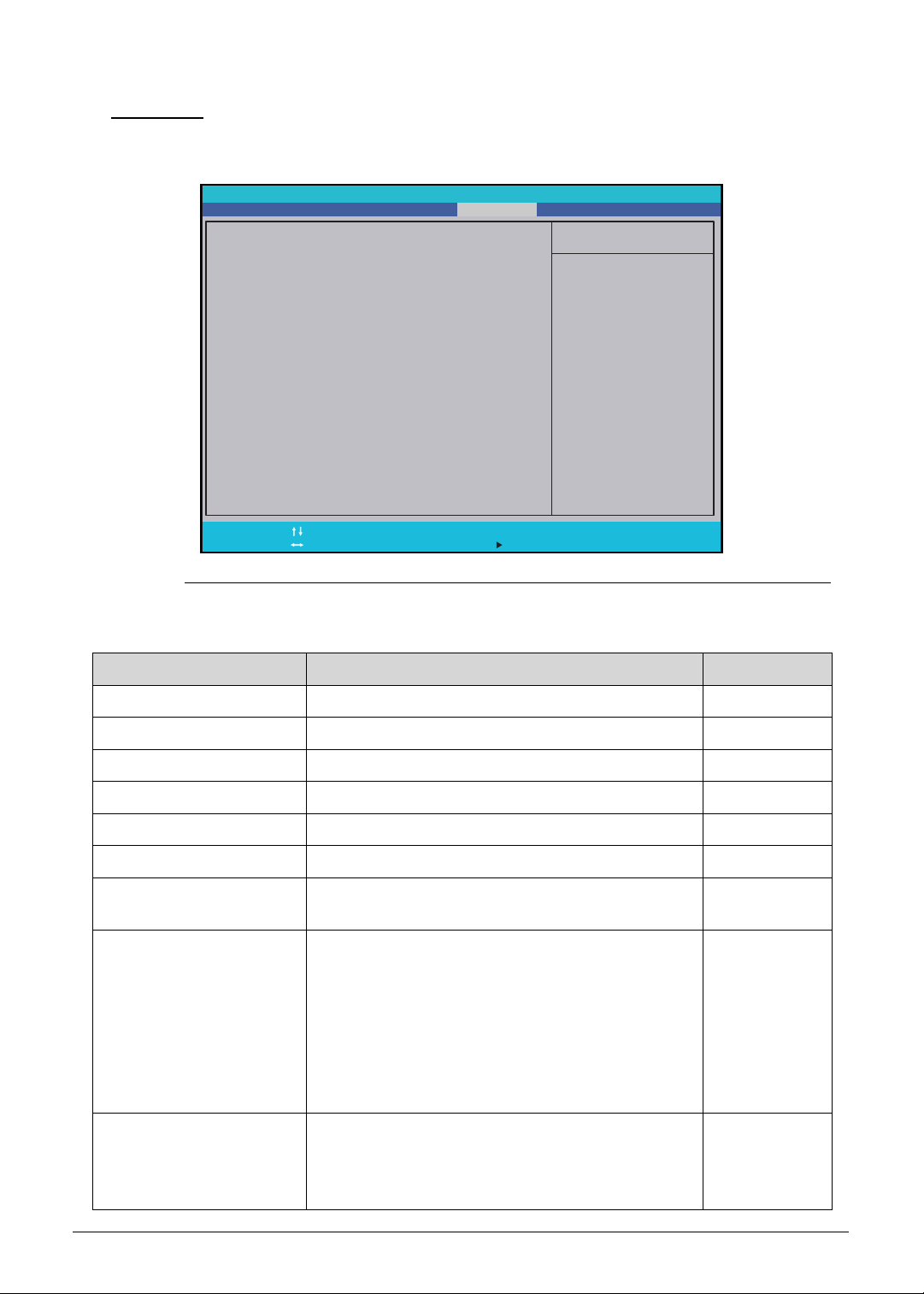
Security 0
Use this tab to safeguard and protect the computer from unauthorized use.
Figure 2-4. BIOS Security
Table 2-4. BIOS Security
Parameter Description Option
Supervisor Password Is Supervisor password setting
Clear or Set
User Password Is User password setting
Clear or Set
HDD Password Is Hard drive password setting
Clear or Set
Set Supervisor Password Option to set the supervisor password –
Set User Password Option to set a user password –
Set HDD Password Option to set the hard drive password –
Password on Boot Option to enable password requirement during
system boot
Enabled or
Disabled
Secure Boot Mode Option to select between two secure boot modes
in firmware setup.
Custom mode provides option to modify the
contents of the Secure Boot signature databases
(PK, KEK, db, dbx).
Standard mode restores the firmware settings to
its factory defaults. Any customized secure boot
variables are also reset to factory defaults.
Standard or
Custom
Erase all Secure Boot
Setting
Option to clear all Secure Boot signature
databases (PK, KEK, db, dbx).
Note: An administrator password is required to
configure this parameter.
–
Item Specific Help
Supervisor Password
c o n t r o l s a c c e s s t o t h e
whole setup utility. It can
b e u s e d t o b o o t u p w h e n
P a s s w o r d o n b o o t i s
enabled.
S u p e r v i s o r P a s s w o r d I s :
U s e r P a s s w o r d I s :
S e t U s e r P a s s w o r d :
Set HDD0 Password:
Set HDD1 Password:
P a s s w o r d o n B o o t :
Secure Boot Mode:
Erase all Secure Boot Setting:
Select an UEFI file as trusted
for executing:
Restore Secure Boot to Factory Default:
Current TPM (TCM) State:
Change TPM (TCM) State:
Clear TPM (TCM):
H D D P a s s w o r d I s :
Set Supervisor Password:
F1
Esc
Help
Exit
Select Item
Select Menu
Change Values
Select Sub-Menu
F5/F6
Enter
F9
F10
Setup Defaults
S a v e a n d E x i t
Clear
Clear
Clear
[Enter]
[Enter]
[Enter]
[Disabled]
Standard
[Enter]
[Enter]
[Enter]
Installed
[Enabled]
[Clear]
[]Enter
MainInformation
InsydeH20 Setup Utility
Security Boot ExitAdvanced

2-10 System Utilities
NOTE:
NOTE:
When prompted to enter the password, three attempts are allowed before
system halts. Resetting the BIOS password may require the user to return the
computer to its dealer.
Select an UEFI file as
trusted for executing
Option to launch an UEFI application from the
FAT32 EFI partition on your hard drive or FAT32
formatted USB drive.
Note: An administrator password is required to
configure this parameter.
–
Restore Secure Boot to
Factory Default
Option to set the secure boot mode to standard
mode which restores the factory defaults.
Note: An administrator password is required to
configure this parameter.
–
Current TPM (TCM) State TPM or TCM state Installed or
Not Installed
Change TPM (TCM)
State
Option to change the TPM or TCM state
Note: This parameter is grayed out if the
Supervisor Password is not set.
The default TPM (TCM) state is set to Enabled
and requires a Supervisor Password to change
the state. When set to Disabled, BIOS will not
initialize the TPM 2.0 device and will hide the
device in the ACPI table. The TPM device will not
appear in the Windows Device Manager.
Enabled or
Disabled
Clear TPM (TCM) Option to clear TPM or TCM
Note: This parameter is grayed out if the
Supervisor Password is not set.
No Change
Table 2-4. BIOS Security (Continued)
Parameter Description Option
System Utilities 2-11
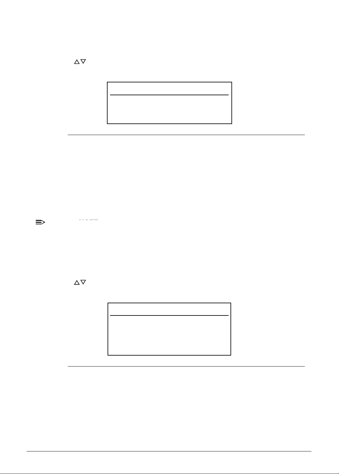
Setting a Password 0
Follow the succeeding instructions to set the user or supervisor passwords.
1. Press to highlight a Set _______ Password parameter and press Enter. The Set
_______ Password dialog box appears.
Figure 2-5. Set Supervisor Password
2. Type a new password in the Enter New Password field and press Enter. Passwords
are not case sensitive and the length must not exceed eight alphanumeric characters
(A-Z, a-z, 0-9).
3. Retype the password in the Confirm New Password field and press Enter.
IMPORTANT:
+
Use care when typing a password. Characters do not appear on the screen.
4. Press Enter.
NOTE:
NOTE:
Users can choose to enable the Password on Boot parameter.
5. Press F10 to save changes and exit from the BIOS Setup Utility.
Removing a Password 0
Perform the following:
1. Press to highlight a Set _______ Password parameter and press Enter. The Set
_______ Password dialog box appears.
Figure 2-6. Set Supervisor Password
2. Type the current password in the Enter Current Password field and press Enter.
3. Press Enter twice
without typing anything in the Enter New Password and Confirm
New Password fields.
4. Press F10 to save changes and exit from the BIOS Setup Utility.
Set Supervisor Password
Enter New Password [ ]
Confirm New Password [ ]
Set Supervisor Password
Enter Current Password [ ]
Enter New Password [ ]
Confirm New Password [ ]
2-12 System Utilities
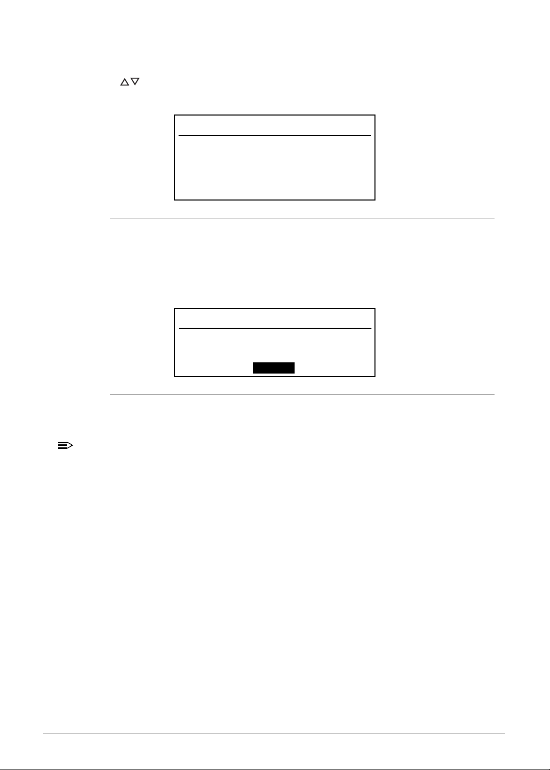
Changing a Password 0
1. Press to highlight a Set _______ Password parameter and press Enter. The Set
_______ Password dialog box appears.
Figure 2-7. Set Supervisor Password
2. Type the current password in the Enter Current Password field and press Enter.
3. Type the new password in the Enter New Password field.
4. Retype the password in the Confirm New Password field.
Figure 2-8. Setup Notice
5. Press Enter. Computer sets Supervisor Password parameter to Set.
NOTE:
NOTE:
Users can choose to enable the Password on Boot parameter.
6. Press F10 to save changes and exit from the BIOS Setup Utility.
Set Supervisor Password
Enter Current Password [ ]
Enter New Password [ ]
Confirm New Password [ ]
Setup Notice
Changes have been saved.
[Continue]
System Utilities 2-13
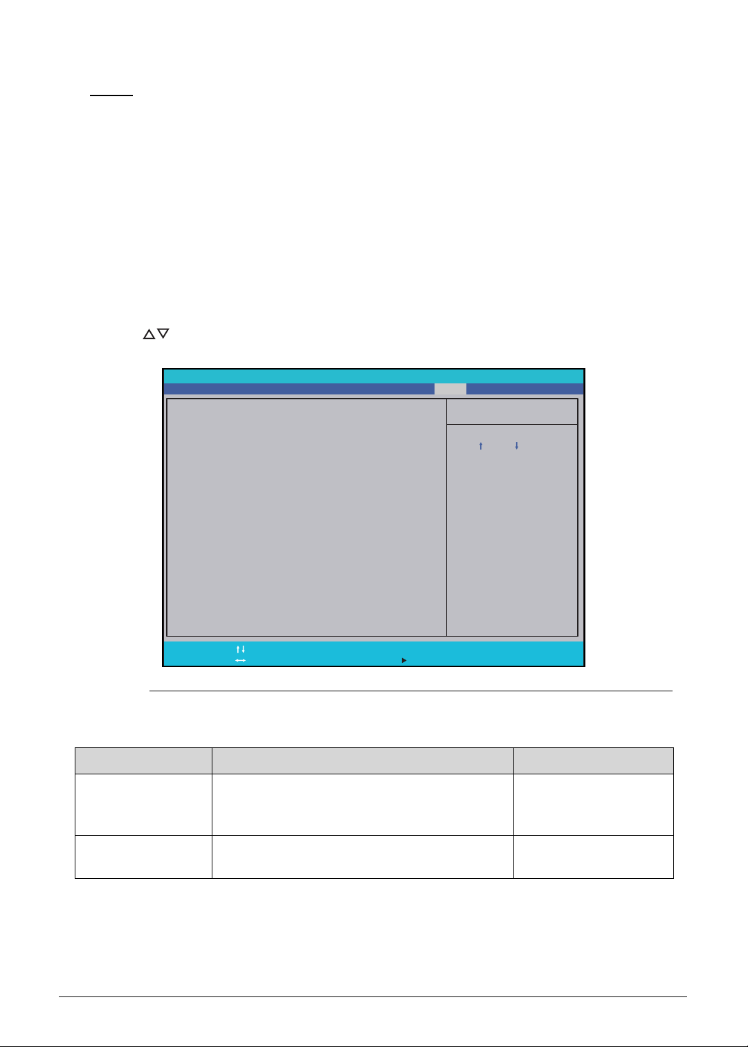
Boot 0
Use this tab to set the preferred drive sequence in which the Setup Utility attempts to boot the
operating system. By default, the computer searches for boot devices in the following order:
1. Windows Boot Manager
2. Primary Hard Disk Drive
3. Optical disc drive
4. External USB bootable device
5. Network boot - IPV4
6. External USB hard drive
7. External USB optical drive
8. Network boot - IPV6
Press to select a device and press F5 or F6 to move it up or down the list.
Figure 2-9. BIOS Boot
Table 2-9. BIOS Boot
Parameter Description Option
Secure Boot Option to enable or disable secure boot check.
Note: Configure this option only if Boot Mode
is set to UEFI.
Enabled or Disabled
Boot Priority Order Option to change the order of drives from
which your computer will try to start up.
–
Item Specific Help
Use < > or < > to select
a d e v i c e , t h e n p r e s s < F 6 >
t o m o v e i t u p t h e l i s t , o r
< F 5 > t o m o v e i t d o w n t h e
list. Pres <Esc> to escape
the menu.
F1
Esc
Help
Exit
Select Item
Select Menu
Change Values
Select Sub-Menu
F5/F6
Enter
F9
F10
Setup Defaults
S a v e a n d E x i t
MainInformation
InsydeH20 Setup Utility
Security Boot ExitAdvanced
Secure Boot:
Boot priority order:
1: Windows Boot Manager
[Enabled]
2-14 System Utilities
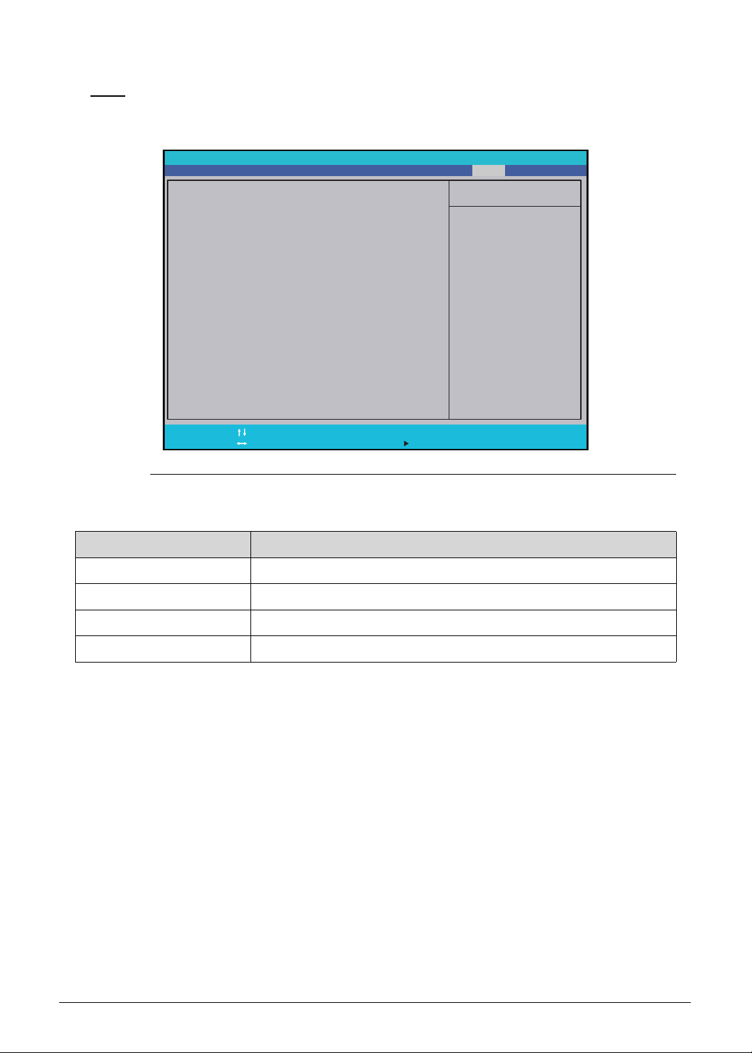
Exit 0
Use the Exit tab to save or discard changes and close the BIOS Setup Utility.
Figure 2-10. BIOS Exit
Table 2-10. Exit Parameters
Parameter Description
Exit Saving Changes Close the BIOS Setup Utility and save the setup changes.
Exit Discarding Changes Close the BIOS Setup Utility without saving the setup changes.
Save and Shutdown Save the setup changes and shutdown the computer.
Load Setup Default Load the default values for all setup items.
Item Specific Help
F1
Esc
Help
Exit
Select Item
Select Menu
Change Values
Select Sub-Menu
F5/F6
Enter
F9
F10
Setup Defaults
S a v e a n d E x i t
MainInformation
InsydeH20 Setup Utility
Security Boot ExitAdvanced
Exit Discarding Changes
Save and Shutdown
Load Setup Defaults
Exit Saving Changes
E x i t S y s t e m S e t u p
and save your changes.

System Utilities 2-15
BIOS Flash Utilities 0
BIOS Flash memory updates are required for the following conditions:
New versions of system programs
New features or options
Restore a BIOS when it becomes corrupted.
Use the Flash utility to update the system BIOS Flash ROM.
NOTE:
NOTE:
If a Crisis Recovery Disc is not available, create one before Flash utility is used.
NOTE:
NOTE:
Do not install memory related drivers (XMS, EMS, DPMI) when Flash is used.
NOTE:
NOTE:
Use AC adapter power supply when running Flash utility. If battery pack does
not contain power to finish loading BIOS Flash, do not boot system.
Perform the following to run Flash.
1. Turn off the computer.
2. Insert the USB device containing the BIOS file and the Crisis Recovery disk files to any
USB port.
3. Press and hold the Fn + Esc keys (this is the BIOS recovery hotkey), then press the
power button.
4. Release the Fn + Esc keys after POST.
NOTE:
NOTE:
Flash utility has auto execution function.
2-16 System Utilities
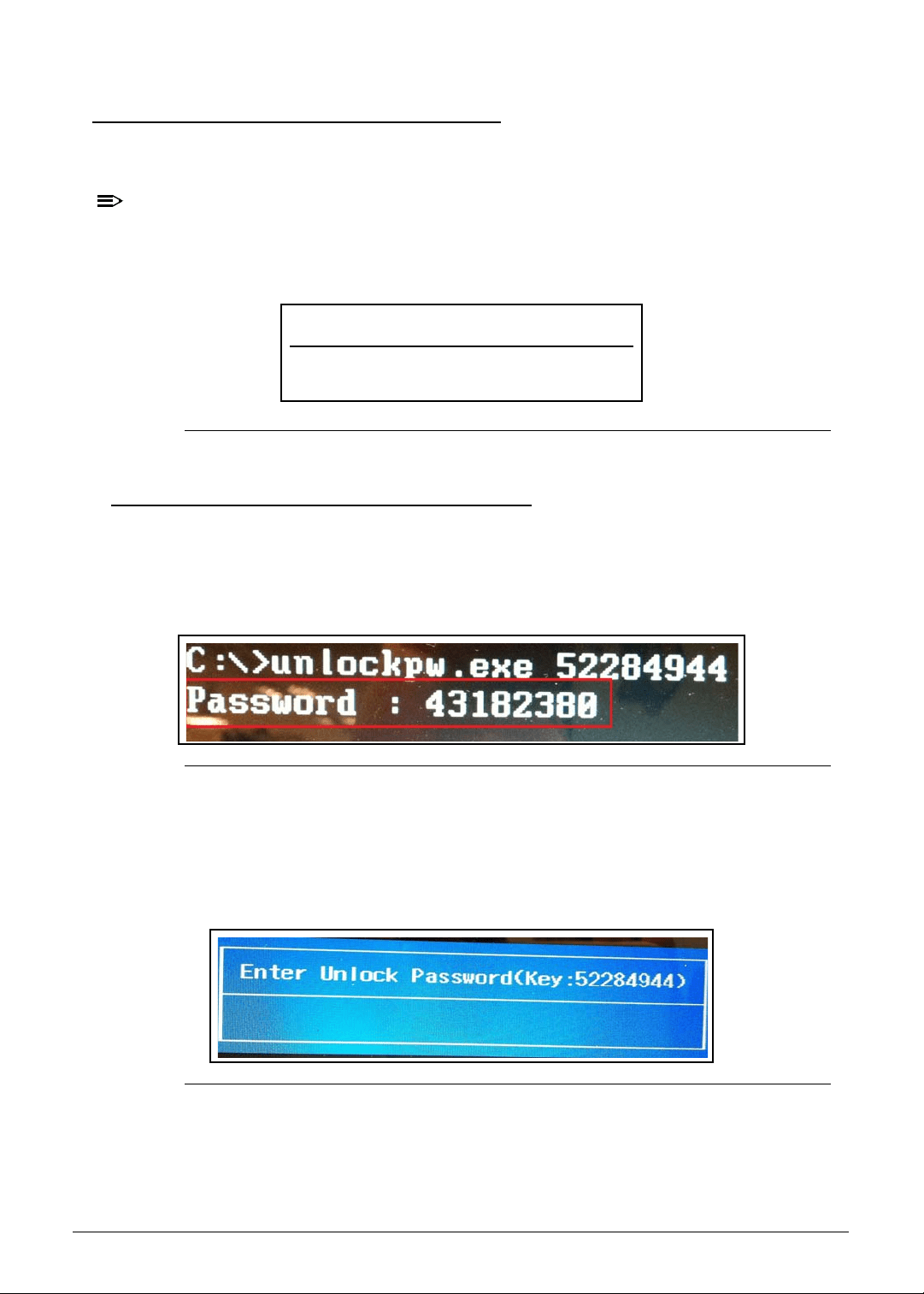
Removing the HDD Password 0
This section explains how to remove the HDD password. The HDD Password Utility can be
executed in DOS and Windows environment.
NOTE:
NOTE:
If the incorrect HDD password is entered three times in succession, an HDD password
error code is generated (Figure 2-11). Write down this password error code then follow
the procedures below on how to remove the HDD password.
Figure 2-11. Password Error Status
Removing the HDD Password (DOS) 0
To reset the HDD password under DOS environment:
1. Open the computer in a DOS environment.
2. Type the following command:
C\> unlockPw.exe XXXXXXXX
Figure 2-12. HDD Master Password
3. Write down the generated master password.
4. Reboot the computer.
5. In the HDD password prompt, type the master password generated in step 2, then press
Enter.
Figure 2-13. HDD Master Password
Password Error Status
HDD password error code (
XXXXXXXX )
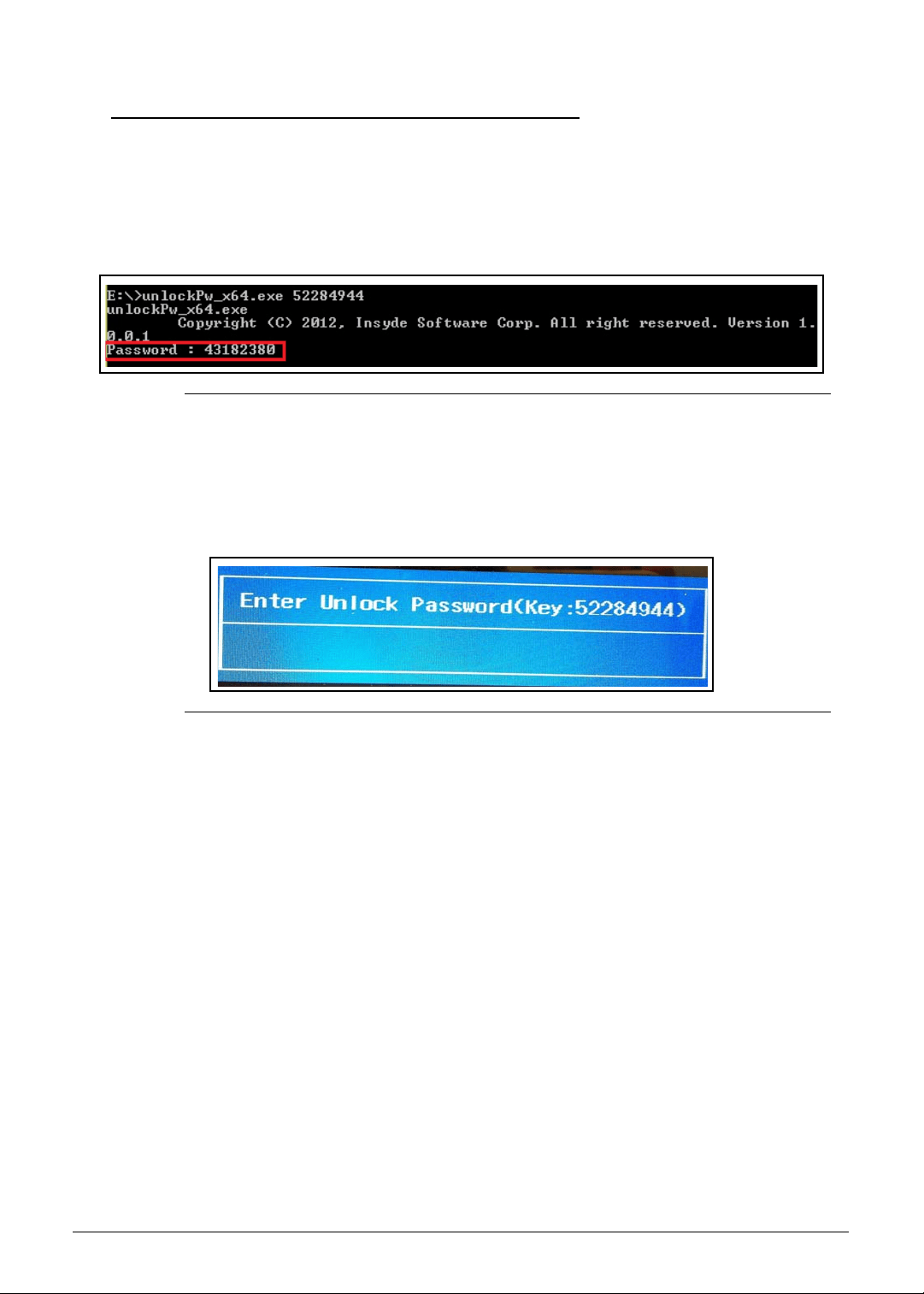
System Utilities 2-17
Removing the HDD Password (Windows) 0
To reset the HDD password under Windows environment:
1. Open the computer in a Windows environment.
2. Open the DOS command window.
3. Type the following command:
C\> unlockPw.exe XXXXXXXX
Figure 2-14. HDD Master Password
4. Write down the generated master password.
5. Reboot the computer.
6. In the HDD password prompt, type the master password generated in step 3, then press
Enter.
Figure 2-15. HDD Master Password
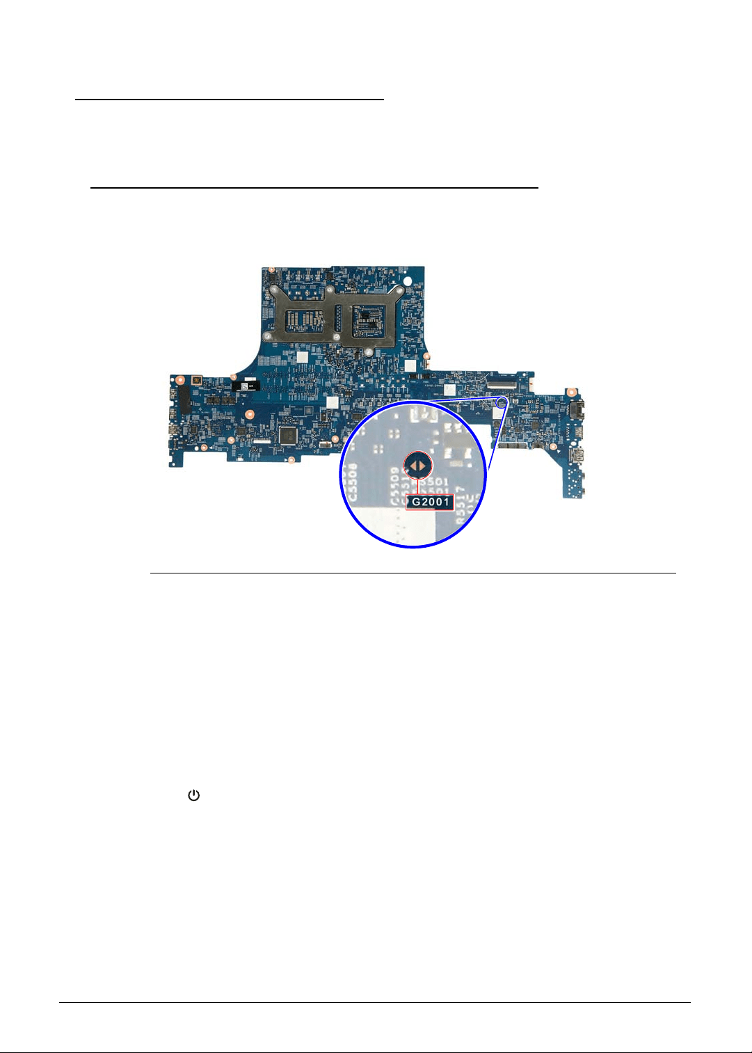
2-18 System Utilities
Removing BIOS Passwords 0
This section explains how to remove the BIOS password. The BIOS password can be
removed by shorting the hardware gap or by executing the BIOS Password Utility.
Removing the BIOS Passwords (Hardware Gap) 0
To clear a lost BIOS password (user or supervisor password), you need to short the clear
password hardware gap (G2001) located on the mainboard.
Figure 2-16. G2001 Hardware Gap
1. Shut down the computer and disconnect the AC adapter and all other peripherals from the
computer.
2. Perform the “Removing the Lower Case” procedure described on page 3-9. Do not
disconnect the DC-In and LCD cables from the mainboard.
3. Perform the “Removing the Battery Pack” procedure described on page 3-11.
4. Locate the G2001 gap.
5. Use an electrical conductivity tool to short the two contacts on the hardware gap together.
6. While resting the tool on the two contacts, plug one end of the AC adapter into the DC-In
jack and plug one end to an electrical outlet.
7. Press the button to turn on the computer.
8. After the BIOS POST, remove the tool from the hardware gap.
9. Perform the “Replacing the Battery Pack” procedure described on page 3-82.
10. Perform the “Replacing the Lower Case” procedure described on page 3-84.
11. Turn on the computer and press F2 during bootup to access the Setup Utility. If no
password prompt appears, the BIOS passwords have been cleared. If the prompt
appears, repeat steps 2-13 until the BIOS passwords have been cleared.
12. Press F9 to load the system defaults.
13. Press F10 to save the changes you made and close the Setup Utility.
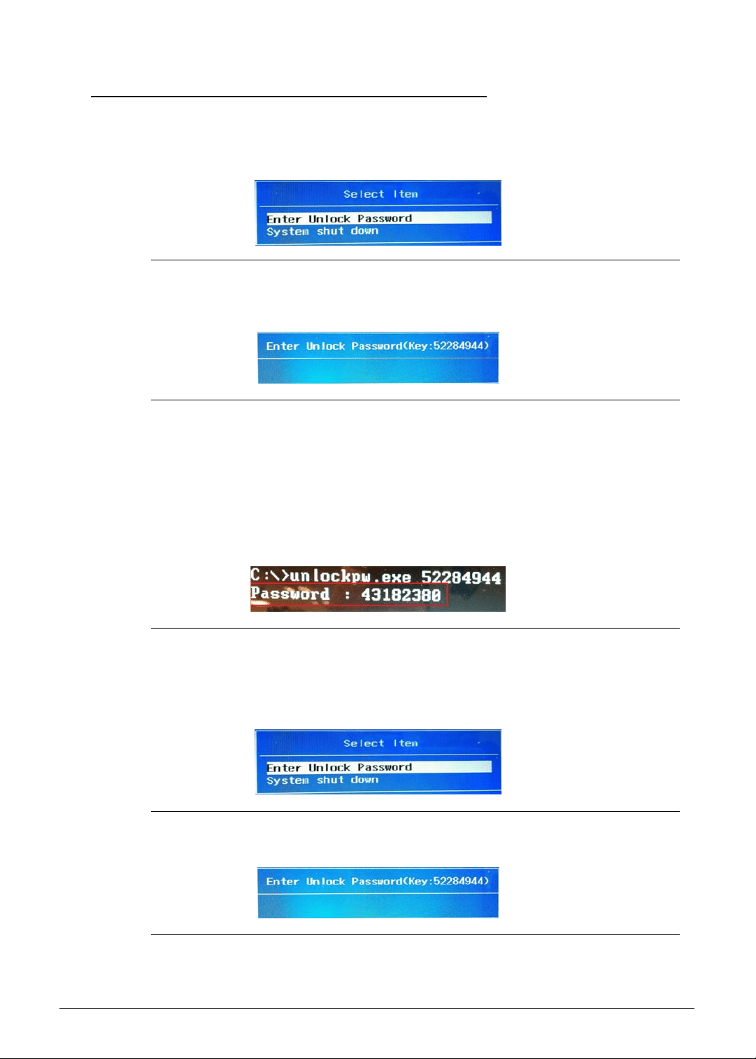
System Utilities 2-19
Removing the BIOS Passwords (Software) 0
The BIOS Password Utility can be executed in DOS and Windows environment.
1. If the incorrect BIOS password is entered three times in succession, a pop out window will
appear (Figure 2-17). Select
Enter Unlock Password to generate a BIOS password
error code.
Figure 2-17. Password Error Status
2. Write down this password error code then follow the procedures below on how to remove
the BIOS password.
Figure 2-18. Password Error Code
DOS Mode 0
To reset the BIOS password under DOS environment:
1. Open the computer in a DOS environment.
2. Type the following command:
C\> unlockpw.exe XXXXXXXX
Figure 2-19. BIOS Supervisor Password
3. Write down the generated supervisor password.
4. Reboot the computer. During POST, press
F2.
5. Select
Enter Unlock Password.
Figure 2-20. Password Error Status
6. Key in the generated supervisor password to unlock the system.
Figure 2-21. Password Unlock Code
7. Reboot the computer and press F2 during POST to enter BIOS Setup Utility.
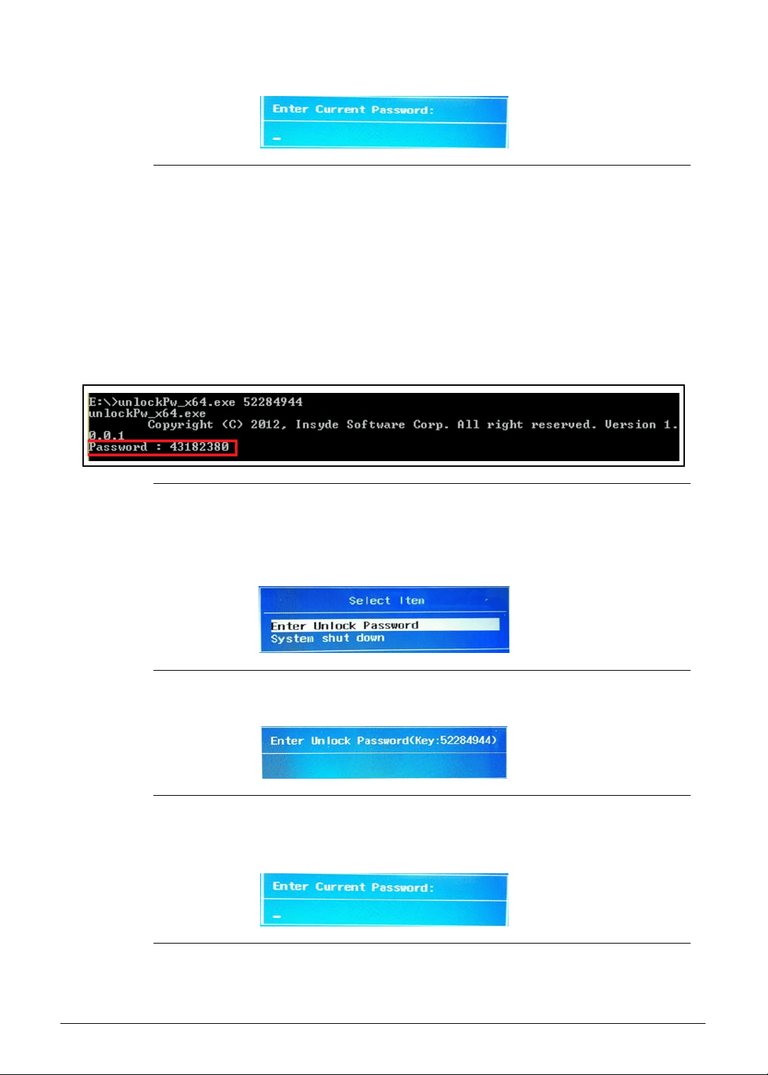
2-20 System Utilities
8. Key in the generated supervisor password in below window to unlock the system.
Figure 2-22. Generated Supervisor Password
9. Perform the “Removing a Password” procedure described on page 2-11 using the
generated supervisor password to clear the password.
Windows Mode 0
To reset the BIOS password under Windows environment:
1. Open DOS Command Prompt.
2. Type the following command:
C\> unlockpw.exe XXXXXXXX
Figure 2-23. BIOS Supervisor Password
3. Write down the generated supervisor password.
4. Reboot the computer. During POST, press
F2.
5. Select
Enter Unlock Password.
Figure 2-24. Password Error Status
6. Key in the generated supervisor password to unlock the system.
Figure 2-25. Password Unlock Code
7. Reboot the computer and press F2 during POST to enter BIOS Setup Utility.
8. Key in the generated supervisor password in below window to unlock the system.
Figure 2-26. Generated Supervisor Password
9. Perform the “Removing a Password” procedure described on page 2-11 using the

System Utilities 2-21
generated supervisor password to clear the password.
2-22 System Utilities
Using DMI Utility 0
The DMI (Desktop Management Interface) Tool generates a standard framework for
managing and tracking system components. The DMI utility supports DOS, Window 7 and
Windows 8 with WMI interface installation.
Using DMI Utility 0
Perform the following steps to use the DMI Utility:
1. Navigate to the correct DMI folder (DMI\Windows\x86 for 32-bit Windows OS or
DMI\WIndows\x64 for 64-bit Windows OS).
2. Using your mouse, right click the wDMI32.exe or wDMI64.exe file and run as
administrator.
NOTE:
NOTE:
Refer to the tables below for a list of DMI tool command usage used in DOS, 32-bit
Windows or 64-bit Windows OS mode.
Table 2-16. DMI Tool Command Usage (DOS)
Parameter Description Command
Manufacture Name Read Manufacture Name
Write Manufacture Name
DMI.EXE /Rm
DMI.EXE /Wm [String]
Product Name Read Product Name
Write Product Name
DMI.EXE /Rp
DMI.EXE /Wp [String]
F/G Serial Number Read F/G Serial Number
Write F/G Serial Number
DMI.EXE /Rfgsn
DMI.EXE /Wfgsn [String]
M/B Serial Number
(Type 2)
Read M/B Serial Number (Type 2)
Write M/B Serial Number (Type 2)
DMI.EXE /Rmbsn
DMI.EXE /Wmbsn [String]
UUID Read UUID
Generate UUID and Write
Write UUID
DMI.EXE /RUUID
DMI.EXE /GWUUID
DMI.EXE /WUUID [String]
Asset tag Read Asset Tag
Write Asset Tag
DMI.EXE /Rasset
DMI.EXE /Wasset [String]
System Utilities 2-23
.
.
3. Reboot when the process has completed.
Table 2-17. DMI Tool Command Usage (32-bit Windows)
Parameter Description Command
Manufacture Name Read Manufacture Name
Write Manufacture Name
wDMI32.EXE /Rm
wDMI32.EXE /Wm [String]
Product Name Read Product Name
Write Product Name
wDMI32.EXE /Rp
wDMI32.EXE /Wp [String]
F/G Serial Number Read F/G Serial Number
Write F/G Serial Number
wDMI32.EXE /Rfgsn
wDMI32.EXE /Wfgsn [String]
M/B Serial Number
(Type 2)
Read M/B Serial Number (Type 2)
Write M/B Serial Number (Type 2)
wDMI32.EXE /Rmbsn
wDMI32.EXE /Wmbsn [String]
UUID Read UUID
Generate UUID and Write
Write UUID
wDMI32.EXE /RUUID
wDMI32.EXE /GWUUID
wDMI32.EXE /WUUID [String]
Asset tag Read Asset Tag
Write Asset Tag
wDMI32.EXE /Rasset
wDMI32.EXE /Wasset [String]
Table 2-18. DMI Tool Command Usage (64-bit Windows)
Parameter Description Command
Manufacture Name Read Manufacture Name
Write Manufacture Name
wDMI64.EXE /Rm
wDMI64.EXE /Wm [String]
Product Name Read Product Name
Write Product Name
wDMI64.EXE /Rp
wDMI64.EXE /Wp [String]
F/G Serial Number Read F/G Serial Number
Write F/G Serial Number
wDMI64.EXE /Rfgsn
wDMI64.EXE /Wfgsn [String]
M/B Serial Number
(Type 2)
Read M/B Serial Number (Type 2)
Write M/B Serial Number (Type 2)
wDMI64.EXE /Rmbsn
wDMI64.EXE /Wmbsn [String]
UUID Read UUID
Generate UUID and Write
Write UUID
wDMI64.EXE /RUUID
wDMI64.EXE /GWUUID
wDMI64.EXE /WUUID [String]
Asset tag Read Asset Tag
Write Asset Tag
wDMI64.EXE /Rasset
wDMI64.EXE /Wasset [String]

2-24 System Utilities

CHAPTER 3
Machine Maintenance

3-2
Machine Disassembly and Replacement . . . . . . . . . . . . . . . . . .3-5
Recommended Equipment . . . . . . . . . . . . . . . . . . . . . . . . . . . .3-5
Replacement Requirements . . . . . . . . . . . . . . . . . . . . . . . . . . .3-5
Pre-disassembly Instructions. . . . . . . . . . . . . . . . . . . . . . . . . . .3-6
Disassembly Process . . . . . . . . . . . . . . . . . . . . . . . . . . . . . . . . . .3-7
Main Unit Disassembly Process . . . . . . . . . . . . . . . . . . . . . . . . .3-8
Main Unit Disassembly Flowchart . . . . . . . . . . . . . . . . . . . . . . .3-8
Removing the Lower Case . . . . . . . . . . . . . . . . . . . . . . . . . . . .3-9
Removing the Battery Pack . . . . . . . . . . . . . . . . . . . . . . . . . . . .3-11
Removing the WLAN Module . . . . . . . . . . . . . . . . . . . . . . . . . .3-13
Removing the RTC Battery . . . . . . . . . . . . . . . . . . . . . . . . . . . .3-15
Removing the DC-In Cable . . . . . . . . . . . . . . . . . . . . . . . . . . . .3-16
Removing the Mainboard. . . . . . . . . . . . . . . . . . . . . . . . . . . . . .3-17
Removing the Touchpad Module. . . . . . . . . . . . . . . . . . . . . . . .3-23
Removing the Left and Right Speakers . . . . . . . . . . . . . . . . . . .3-25
Removing the WLAN Antenna. . . . . . . . . . . . . . . . . . . . . . . . . .3-27
Removing the Turbo Key Module . . . . . . . . . . . . . . . . . . . . . . .3-29
Removing the Memory Modules . . . . . . . . . . . . . . . . . . . . . . . .3-32
Removing the SSD Modules . . . . . . . . . . . . . . . . . . . . . . . . . . .3-34
Removing the Thermal Module . . . . . . . . . . . . . . . . . . . . . . . . .3-36
Removing the Upper Case . . . . . . . . . . . . . . . . . . . . . . . . . . . .3-39
LCD Module Disassembly Process . . . . . . . . . . . . . . . . . . . . . . .3-41
LCD Module Disassembly Flowchart. . . . . . . . . . . . . . . . . . . . .3-41
Removing the LCD Bezel . . . . . . . . . . . . . . . . . . . . . . . . . . . . .3-42
Removing the LCD Hinge Brackets . . . . . . . . . . . . . . . . . . . . . .3-43
Removing the LCD Panel . . . . . . . . . . . . . . . . . . . . . . . . . . . . .3-44
Removing the Camera Module . . . . . . . . . . . . . . . . . . . . . . . . .3-47
LCD Module Reassembly Process . . . . . . . . . . . . . . . . . . . . . . .3-49
Replacing the Camera Module . . . . . . . . . . . . . . . . . . . . . . . . .3-49
Replacing the LCD Panel . . . . . . . . . . . . . . . . . . . . . . . . . . . . .3-51
Replacing the LCD Hinge Brackets . . . . . . . . . . . . . . . . . . . . . .3-56
Replacing the LCD Bezel. . . . . . . . . . . . . . . . . . . . . . . . . . . . . .3-57
Main Unit Reassembly Process . . . . . . . . . . . . . . . . . . . . . . . . . .3-58
Replacing the Upper Case. . . . . . . . . . . . . . . . . . . . . . . . . . . . .3-58
Replacing the Thermal Module . . . . . . . . . . . . . . . . . . . . . . . . .3-59
Replacing the SSD Modules . . . . . . . . . . . . . . . . . . . . . . . . . . .3-61
Replacing the Memory Module . . . . . . . . . . . . . . . . . . . . . . . . .3-62
Replacing the Turbo Key Module . . . . . . . . . . . . . . . . . . . . . . .3-64

3-3
Replacing the WLAN Antenna . . . . . . . . . . . . . . . . . . . . . . . . . .3-67
Replacing the Left and Right Speakers . . . . . . . . . . . . . . . . . . .3-68
Replacing the Touchpad Module . . . . . . . . . . . . . . . . . . . . . . . .3-70
Replacing the Mainboard. . . . . . . . . . . . . . . . . . . . . . . . . . . . . .3-72
Replacing the DC-In Cable . . . . . . . . . . . . . . . . . . . . . . . . . . . .3-78
Replacing the RTC Battery . . . . . . . . . . . . . . . . . . . . . . . . . . . .3-79
Replacing the WLAN Module. . . . . . . . . . . . . . . . . . . . . . . . . . .3-80
Replacing the Battery Pack . . . . . . . . . . . . . . . . . . . . . . . . . . . .3-82
Replacing the Lower Case. . . . . . . . . . . . . . . . . . . . . . . . . . . . .3-84

3-4

Machine Maintenance 3-5
Machine Maintenance
This chapter contains step-by-step procedures on how to disassemble the notebook
computer for maintenance and troubleshooting.
Machine Disassembly and Replacement 0
Cable paths and positioning may not represent the actual model. During the removal and
installation of the components, ensure all available cable channels and clips are used and
that the cables are replaced in the same position.
The screws for the different components vary in size. During the disassembly process, group
the screws with the corresponding components to avoid mismatch when putting back the
components.
The product previews seen in the disassembly procedures may not represent the final
product color or configuration.
Recommended Equipment 0
To disassemble the computer, the following tools are suggested:
Wrist grounding strap and conductive mat for preventing electrostatic discharge
Non-marring scribe
Phillips screwdriver
Flat-blade screwdriver
Plastic flat screwdriver
Plastic tweezers
Cyanoacrylate glue
Replacement Requirements 0
NOTE:
NOTE:
Cabling and components require adhesive to be applied during the replacement and
reassembly process.
NOTE:
NOTE:
When replacing individual component, the system should be reset to the factory default
condition by removing and replacing the RTC battery. Please refer to the procedures
described on pages 3-15 and 3-79.
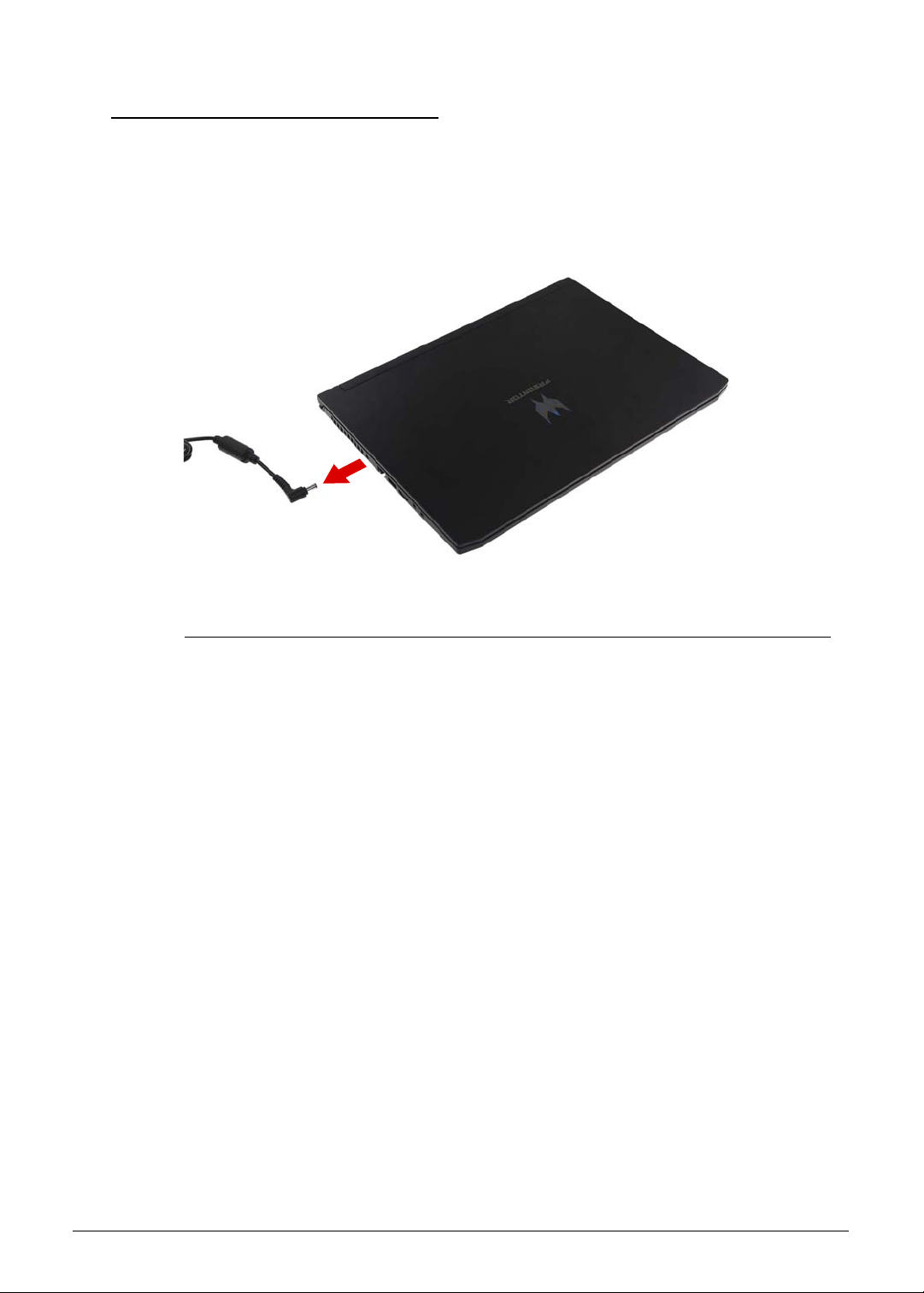
3-6 Machine Maintenance
Pre-disassembly Instructions 0
Before proceeding with the disassembly procedure, make sure that you do the following:
1. Turn off the power to the system and all peripherals.
2. Unplug the AC adapter and all power and signal cables from the system.
Figure 3-1. AC Adapter
3. Place the system on a flat, stable surface.

Machine Maintenance 3-7
Disassembly Process 0
The disassembly process is divided into the following stages:
Main Unit Disassembly
LCD Module Disassembly
The flowcharts provided in the succeeding disassembly sections illustrate the entire
disassembly sequence. Observe the order of the sequence to avoid damage to any of the
hardware components. For example, if you want to remove the mainboard, you must first
remove the keyboard, then disassemble the inside assembly frame in that order.
Table 3-1. Main Screw List
Screw Quantity Acer Part Number
M2 x L4 17 86.00E92.724
M2 x L2 8 86.MQJN1.001
M2.5 x L6 10 86.Q50N1.001
M2.5 x L2.5 6 86.9AR13.2R5
M2 x L2.5 4 86.M92N1.005
M2.5 x L6 4 86.MVAN1.002
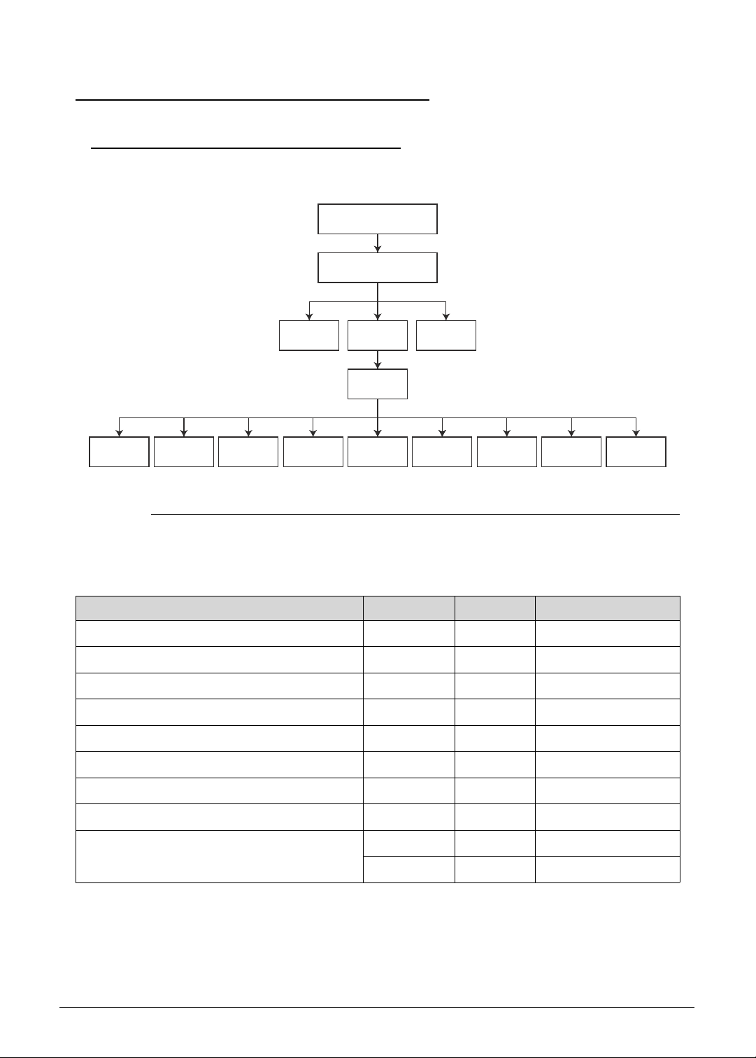
3-8 Machine Maintenance
Main Unit Disassembly Process 0
Main Unit Disassembly Flowchart 0
Figure 3-2. Main Unit Disassembly Flowchart
Table 3-2. Screw List
Step Screw Quantity Acer Part Number
Lower Case Disassembly M2.5 x L6 10 86.Q50N1.001
Battery Pack Disassembly M2 x L4 2 86.00E92.724
WLAN Module Disassembly M2 x L4 1 86.00E92.724
Mainboard Disassembly M2 x L4 6 86.00E92.724
Touchpad Module Disassembly M2 x L2 4 86.MQJN1.001
Turbo Key Module Disassembly M2 x L2.5 2 86.M92N1.005
SSD Modules Disassembly M2 x L2.5 2 86.M92N1.005
Thermal Module Disassembly M2 x L4 6 86.00E92.724
Upper Case Disassembly M2.5 x L6 4 86.MVAN1.002
M2 x L2 2 86.MQJN1.001
SSD
MODULES
LOWER CASE
BATTERY PACK
DC-IN
MODULE
TOUCHPAD
MODULE
TURBO KEY
MODULE
MEMORY
MODULES
RTC
BATTERY
THERMAL
MODULE
LCD
MODULE
UPPER
CASE
MAIN
BOARD
WLAN
ANTENNA
SPEAKER
MODULE
WLAN
MODULE
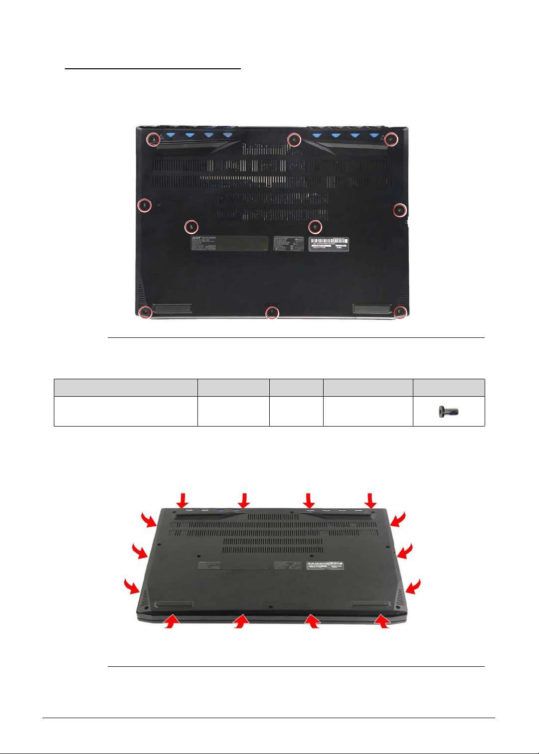
Machine Maintenance 3-9
Removing the Lower Case 0
1. Turn the computer over so that the base is facing up.
2. Remove the ten screws securing the lower case to the upper case.
Figure 3-3. Lower Case Screws
3. Pry the sides of the lower case from the upper case to disengage the latches.
Figure 3-4. Lower Case Latches
Table 3-3. Screws
Step Screw Quantity Torque Screw Type
Lower Case Disassembly M2.5 × L6 10 3.0 ± 0.45 kgf cm
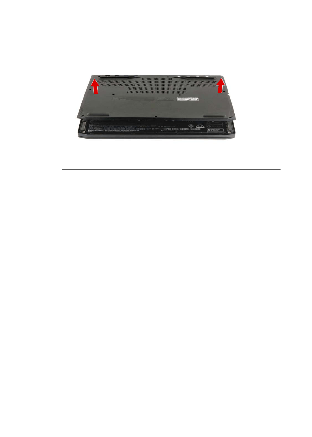
3-10 Machine Maintenance
4. Remove the lower case from the upper case.
Figure 3-5. Lower Case
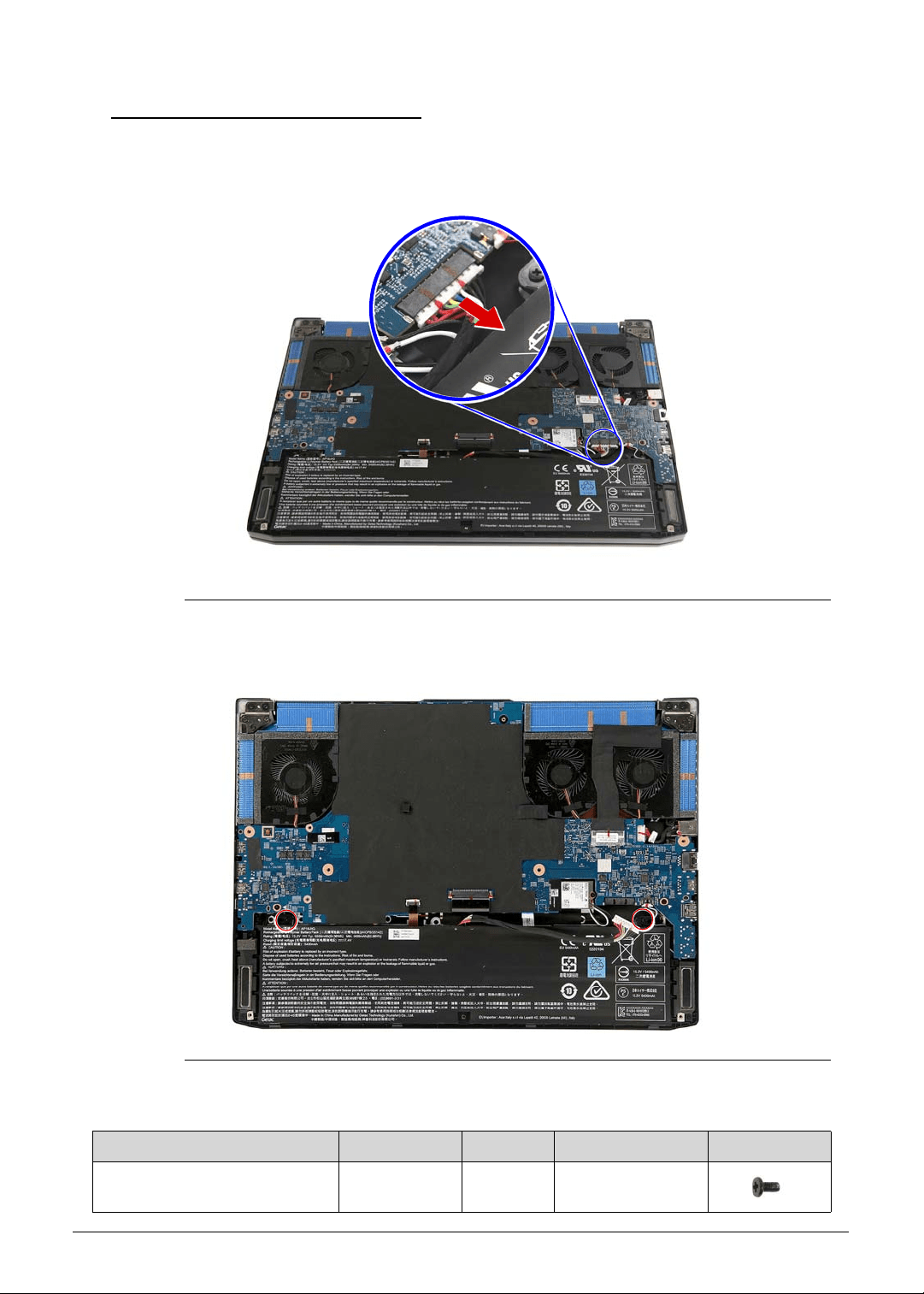
Machine Maintenance 3-11
Removing the Battery Pack 0
1. Perform the Removing the Lower Case procedure described on page 3-9.
2. Disconnect the battery cable from the mainboard.
Figure 3-6. Mainboard Connector - Battery Cable
3. Remove the two screws securing the battery pack to the upper case.
Figure 3-7. Battery Pack Screws
Table 3-7. Screws
Step Screw Quantity Torque Screw Type
Battery Pack Disassembly M2 × L4 2 1.6 ± 0.24 kgf cm
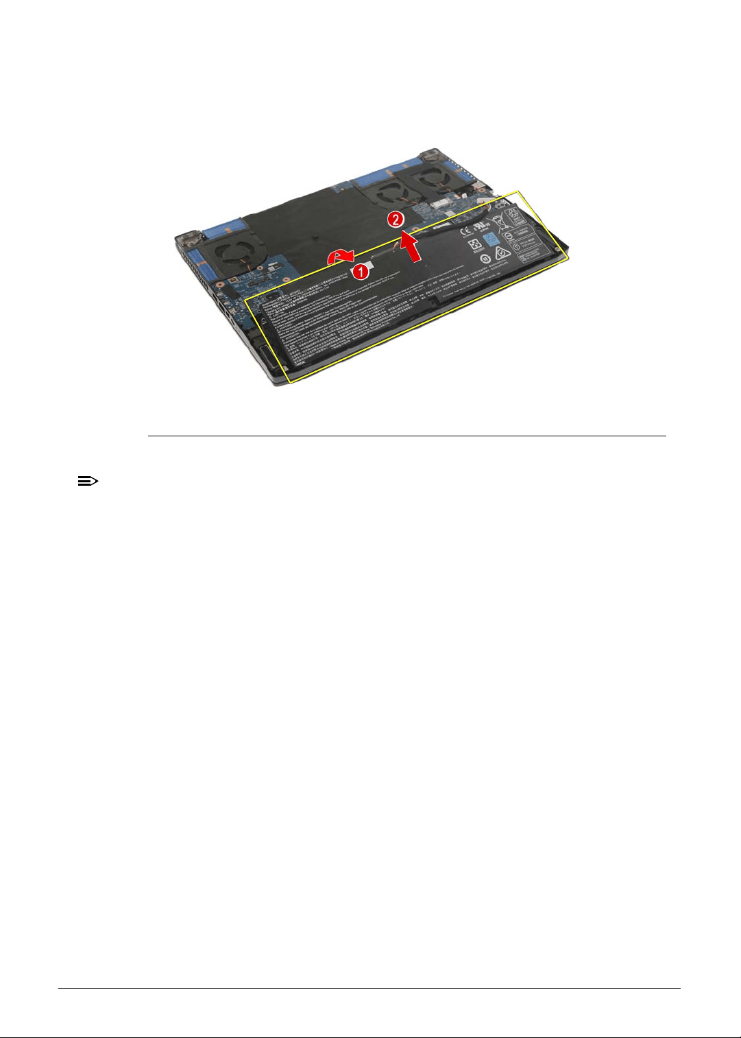
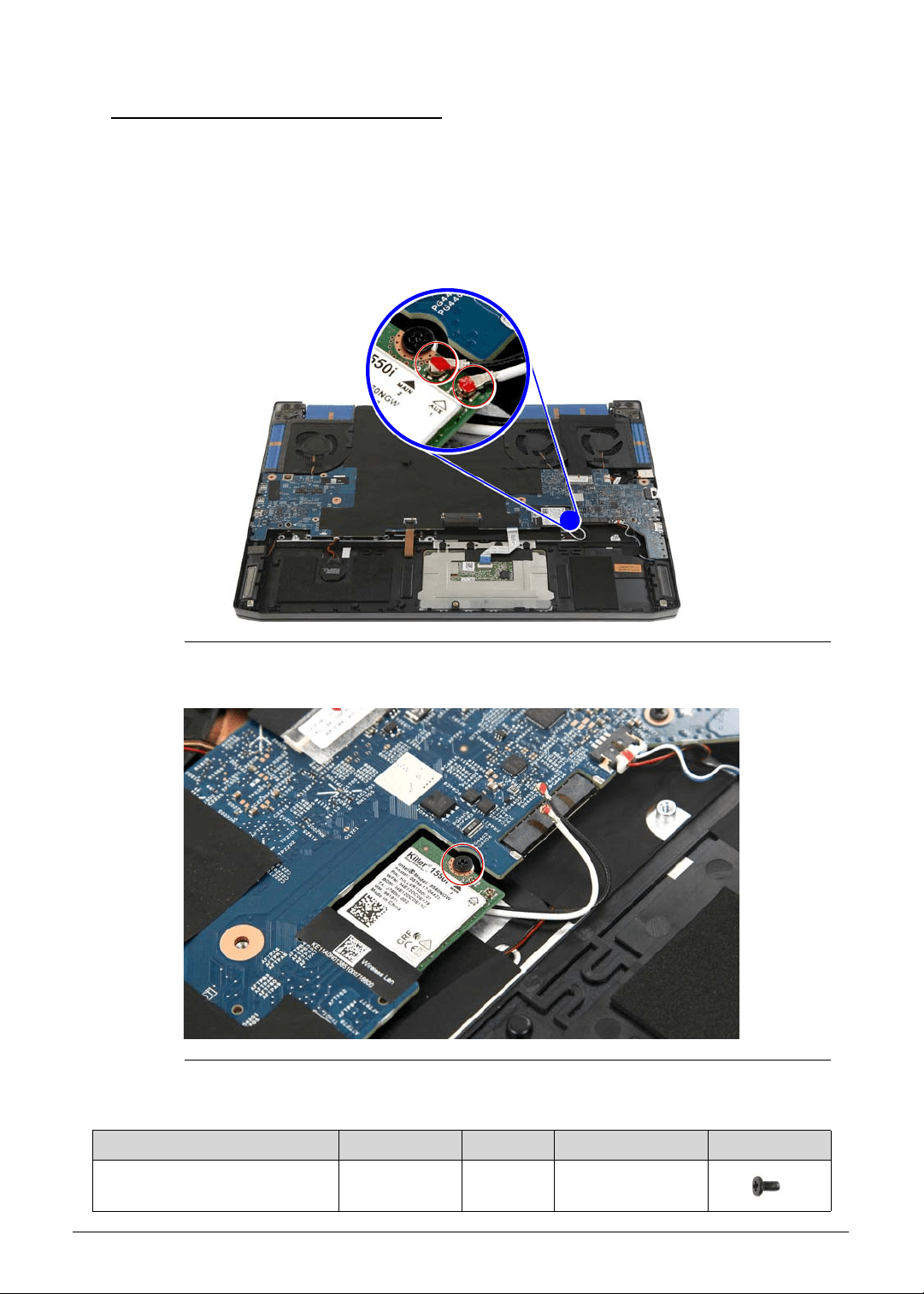
Machine Maintenance 3-13
Removing the WLAN Module 0
1. Perform the Removing the Lower Case procedure described on page 3-9.
2. Perform the Removing the Battery Pack procedure described on page 3-11.
3. Unplug the WLAN antenna cables from the WLAN module.
IMPORTANT:
+
For reference during machine reassembly, note which cable color
corresponds to the main and auxiliary connectors.
Figure 3-9. WLAN Antenna Cables
4. Remove the one screw securing the WLAN module to the upper case.
Figure 3-10. WLAN Module Screw
Table 3-10. Screw
Step Screw Quantity Torque Screw Type
WLAN Module Disassembly M2 × L4 6 1.6 ± 0.24 kgf cm
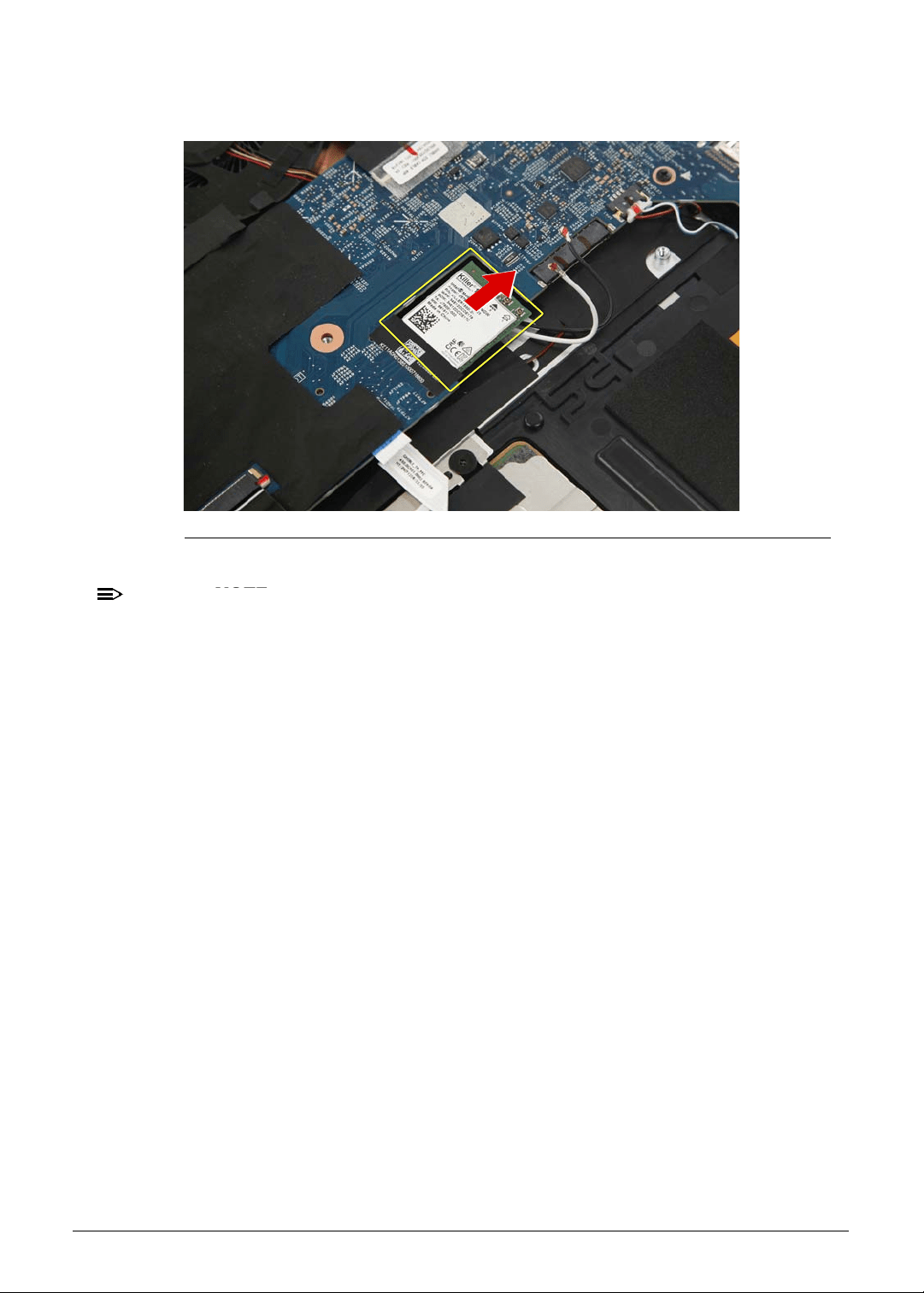
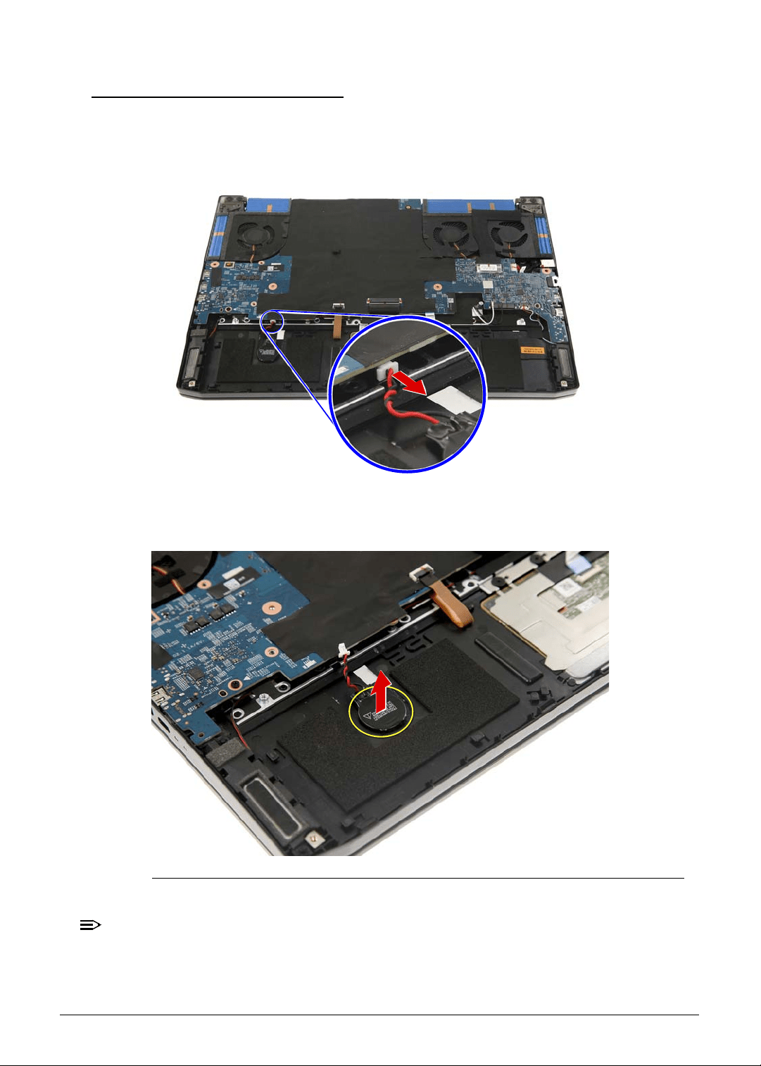
Machine Maintenance 3-15
Removing the RTC Battery 0
1. Perform the Removing the Lower Case procedure described on page 3-9.
2. Perform the Removing the Battery Pack procedure described on page 3-11.
3. Disconnect the RTC battery cable from the mainboard.
Figure 3-12. Mainboard Connector - RTC Battery Cable
4. Gently peel off the RTC battery from the upper case.
Figure 3-13. RTC Battery
NOTE:
NOTE:
WEEE Annex VII part. The RTC battery in Figure 3-13 is highlighted with a yellow
circle. Detach the RTC battery and follow the local regulations for disposing it.
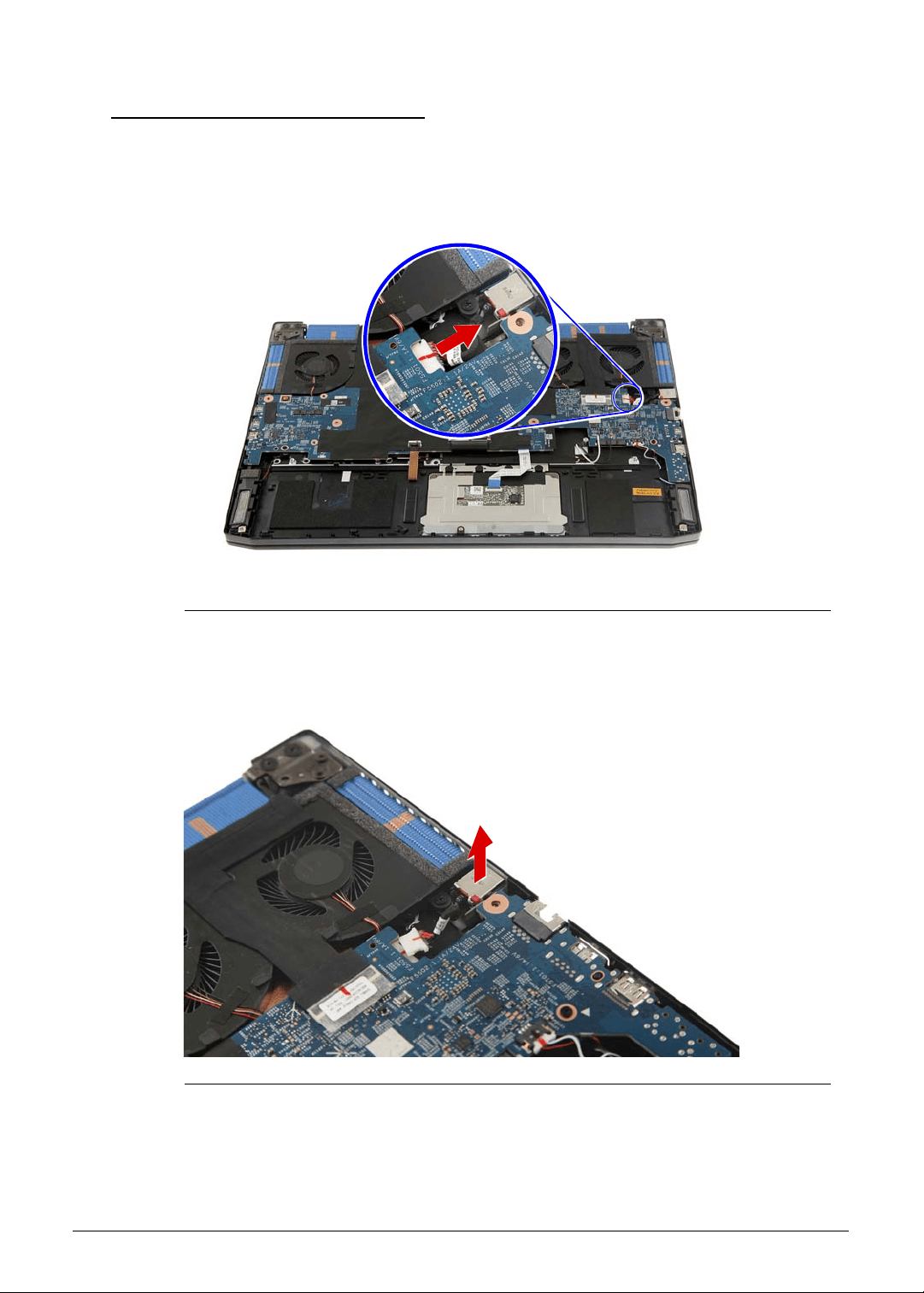
3-16 Machine Maintenance
Removing the DC-In Cable
0
1. Perform the Removing the Lower Case procedure described on page 3-9.
2. Perform the Removing the Battery Pack procedure described on page 3-11.
3. Disconnect the DC-In cable from the mainboard.
Figure 3-14. Mainboard Connector - DC-In Cable
4. Detach the DC-In cable from the upper case.
Figure 3-15. DC-In Cable
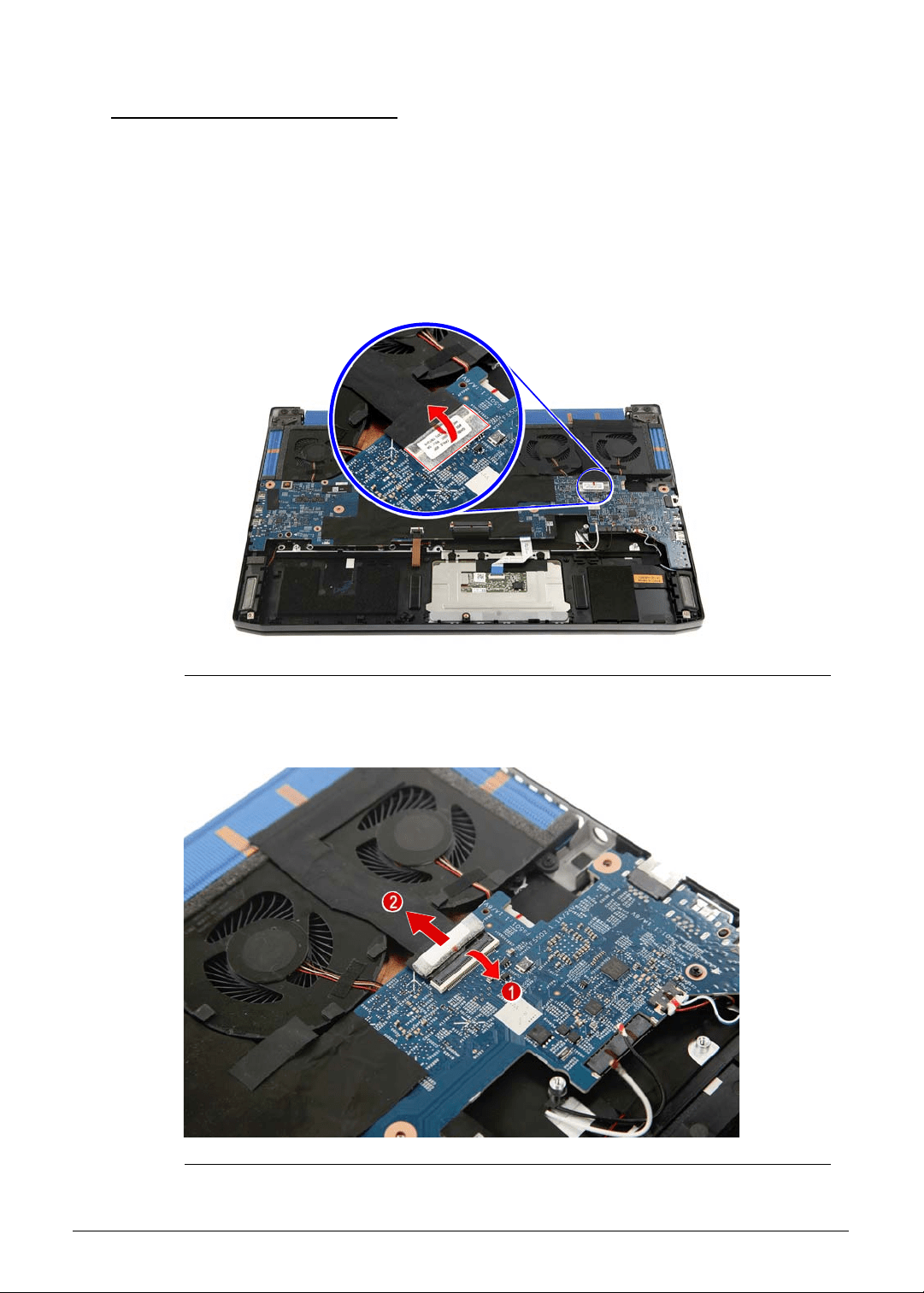
Machine Maintenance 3-17
Removing the Mainboard 0
1. Perform the Removing the Lower Case procedure described on page 3-9.
2. Perform the Removing the Battery Pack procedure described on page 3-11.
3. Perform the Removing the WLAN Module procedure described on page 3-13.
4. Perform the Removing the RTC Battery procedure described on page 3-15.
5. Perform the Removing the DC-In Cable procedure described on page 3-16.
6. Carefully peel off the tape securing the eDP cable to the mainboard.
Figure 3-16. eDP Cable Transparent Adhesive Tape
7. Disconnect the eDP cable from the mainboard.
Figure 3-17. Mainboard Connector - eDP Cable
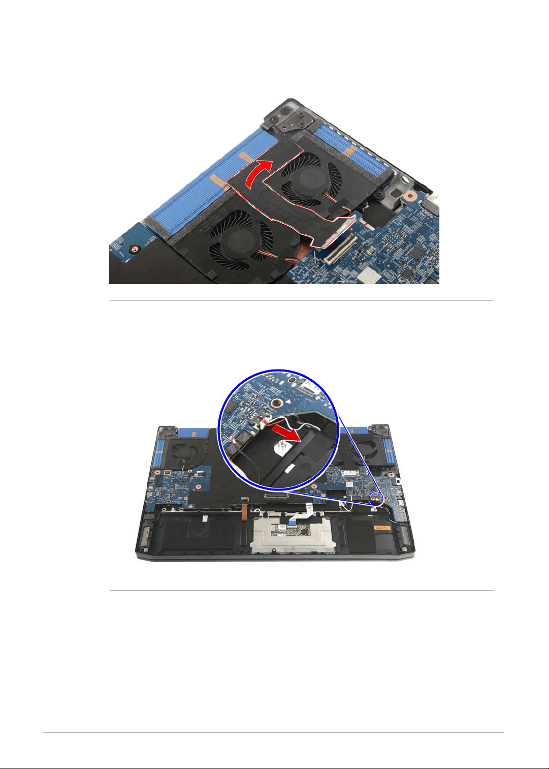
3-18 Machine Maintenance
8. Carefully peel off the eDP cable from the thermal fan.
Figure 3-18. eDP Cable Self-Adhesive Tape
9. Disconnect the speaker cable from the mainboard.
Figure 3-19. Mainboard Connector - Speaker Cable
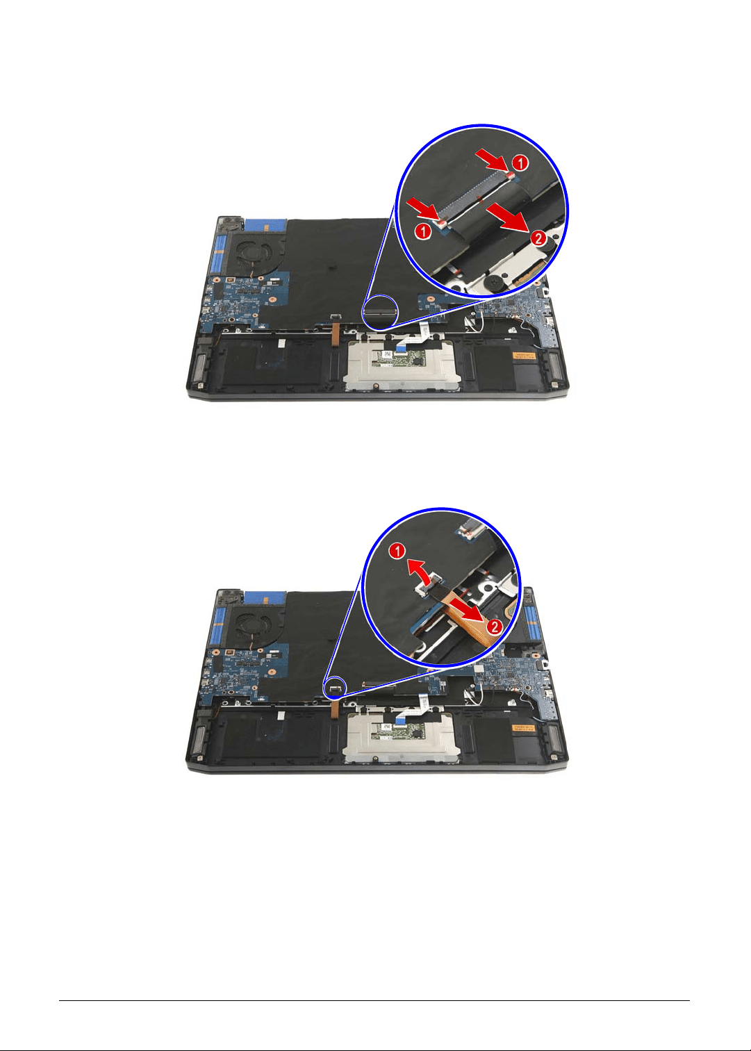
Machine Maintenance 3-19
10. Disconnect the keyboard cable from the mainboard.
Figure 3-20. Mainboard Connector - Keyboard Cable
11. Disconnect the keyboard backlight cable from the mainboard.
Figure 3-21. Mainboard Connector - Keyboard Backlight Cable
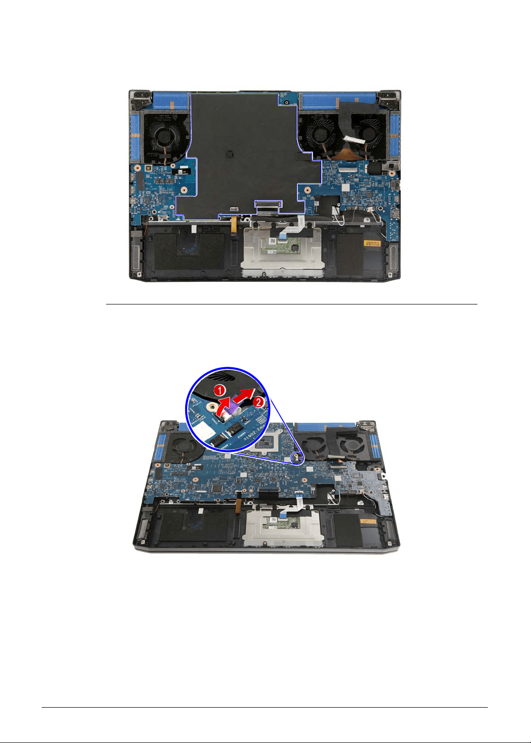
3-20 Machine Maintenance
12. Carefully peel off the mylar from the mainboard.
Figure 3-22. Mainboard Mylar
13. Disconnect the turbo key cable from the mainboard.
Figure 3-23. Mainboard Connector - Turbo Key Cable
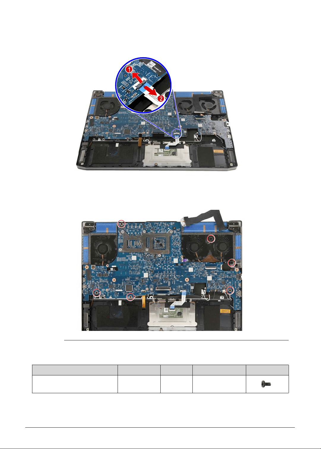
Machine Maintenance 3-21
14. Disconnect the touchpad cable from the mainboard.
Figure 3-24. Mainboard Connector - Touchpad Cable
15. Remove the six screws securing the mainboard to the upper case.
Figure 3-25. Mainboard Screws
Table 3-25. Screws
Step Screw Quantity Torque Screw Type
Mainboard Disassembly M2 × L4 6 1.6 ± 0.24 kgf cm
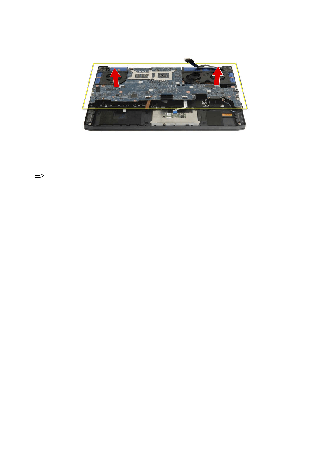
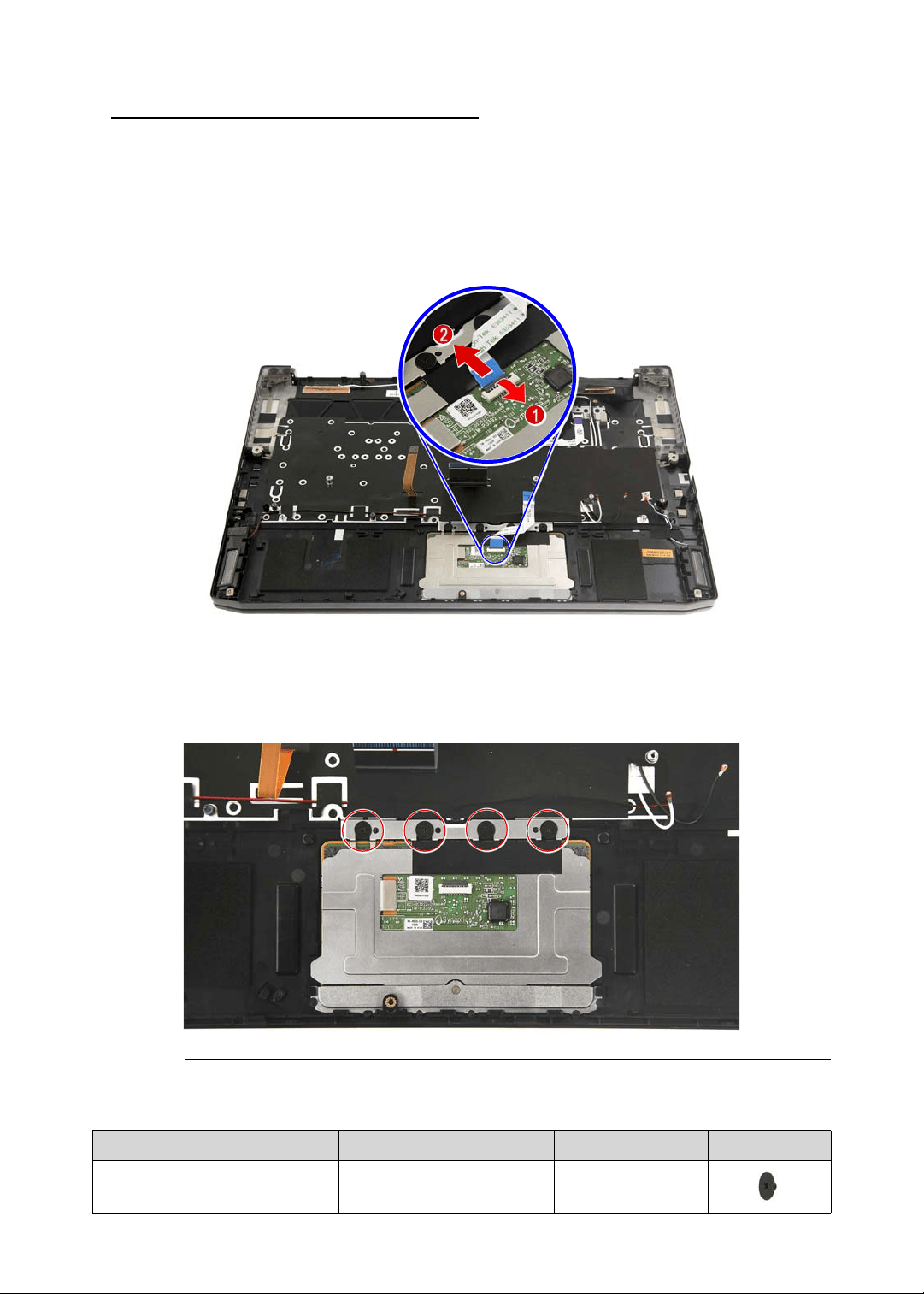
Machine Maintenance 3-23
Removing the Touchpad Module 0
1. Perform the Removing the Lower Case procedure described on page 3-9.
2. Perform the Removing the Battery Pack procedure described on page 3-11.
3. Gently lift the mylar covering the touchpad cable and disconnect the touchpad cable from
the mainboard.
4. Disconnect the touchpad cable from the touchpad module.
Figure 3-27. Touchpad Connector - Touchpad Cable
5. Remove the four screws securing the touchpad module to the upper case.
Figure 3-28. Touchpad Module Screws
Table 3-28. Screws
Step Screw Quantity Torque Screw Type
Touchpad Module
Disassembly
M2 × L2 4 1.6 ± 0.24 kgf cm
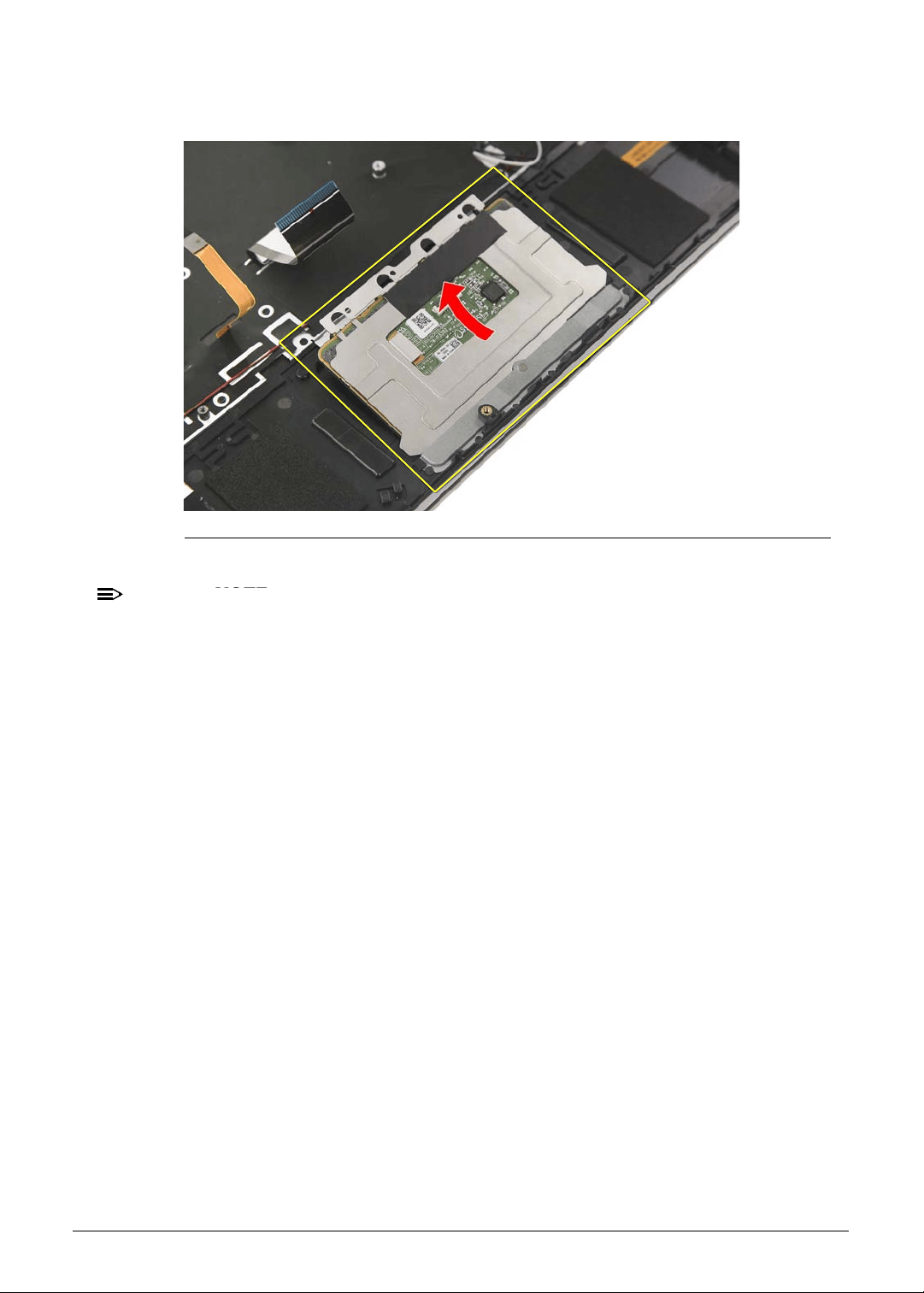
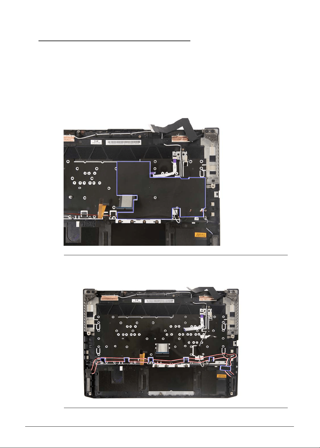
Machine Maintenance 3-25
Removing the Left and Right Speakers 0
1. Perform the Removing the Lower Case procedure described on page 3-9.
2. Perform the Removing the Battery Pack procedure described on page 3-11.
3. Perform the Removing the WLAN Module procedure described on page 3-13.
4. Perform the Removing the RTC Battery procedure described on page 3-15.
5. Perform the Removing the DC-In Cable procedure described on page 3-16.
6. Perform the Removing the Mainboard procedure described on page 3-17.
7. Carefully peel off the mylar from the upper case.
Figure 3-30. Upper Case Mylar
8. Peel off the tapes and release the speaker cables from the cable guides of the upper case.
Figure 3-31. Upper Case Adhesive Tapes and Cable Guides - Speaker Cables
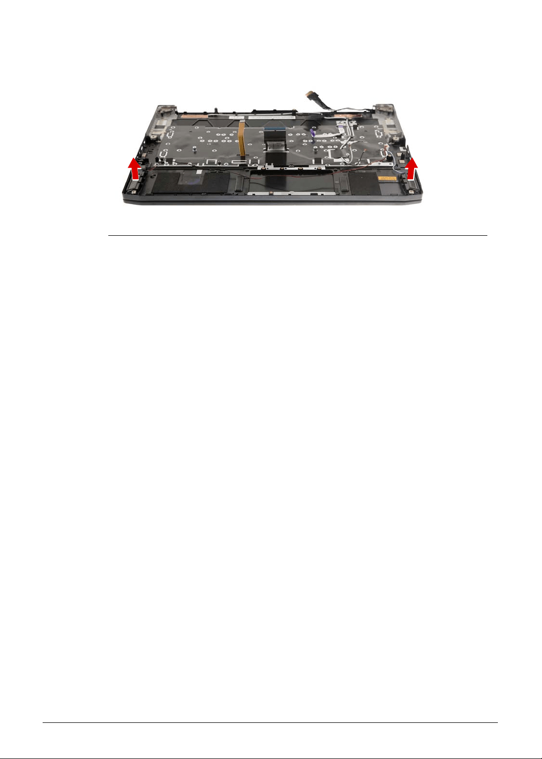
3-26 Machine Maintenance
9. Lift up and remove the left and right speakers.
Figure 3-32. Left and Right Speakers
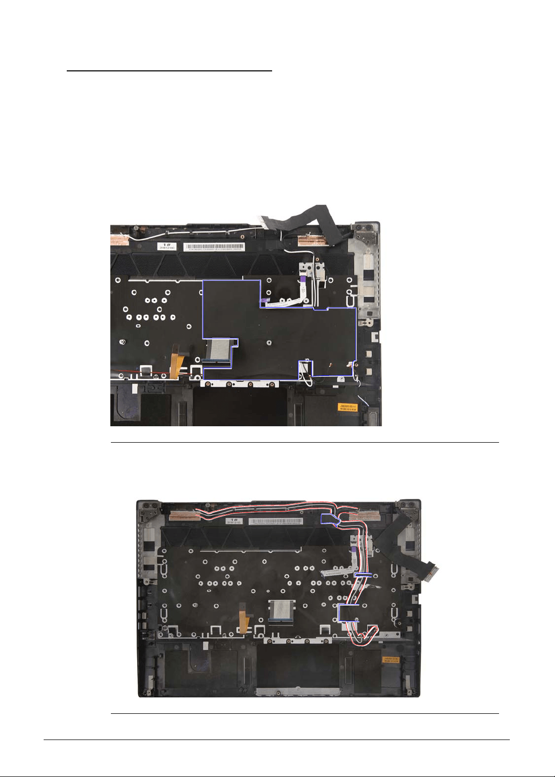
Machine Maintenance 3-27
Removing the WLAN Antenna 0
1. Perform the Removing the Lower Case procedure described on page 3-9.
2. Perform the Removing the Battery Pack procedure described on page 3-11.
3. Perform the Removing the WLAN Module procedure described on page 3-13.
4. Perform the Removing the RTC Battery procedure described on page 3-15.
5. Perform the Removing the DC-In Cable procedure described on page 3-16.
6. Perform the Removing the Mainboard procedure described on page 3-17.
7. Carefully peel off the mylar from the upper case.
Figure 3-33. Upper Case Mylar
8. Peel off the tapes and release the cables from the cable guides of the upper case.
Figure 3-34. Upper Case Adhesive Tapes and Cable Guides - Antenna Cables
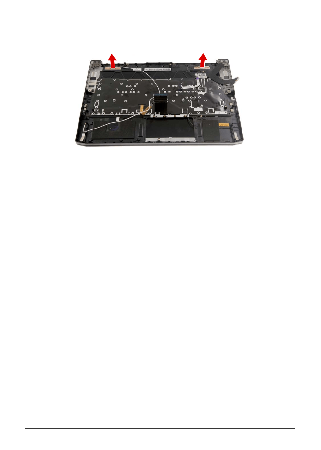
3-28 Machine Maintenance
9. Gently peel off the WLAN antenna from the upper case.
Figure 3-35. WLAN Antenna
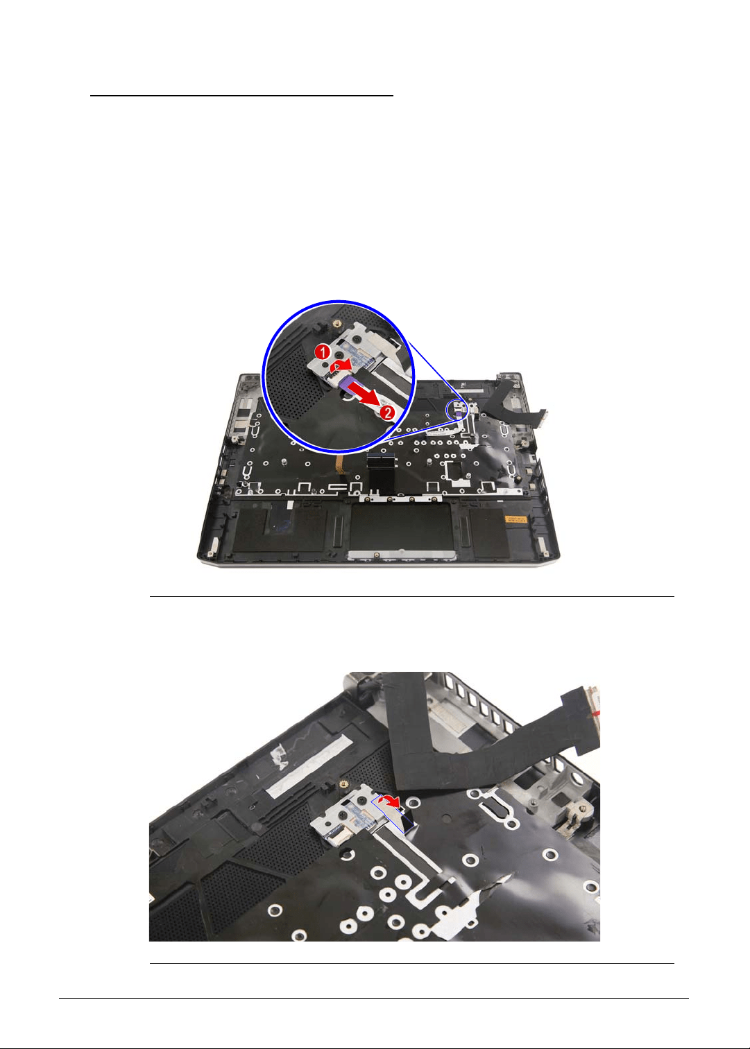
Machine Maintenance 3-29
Removing the Turbo Key Module 0
1. Perform the Removing the Lower Case procedure described on page 3-9.
2. Perform the Removing the Battery Pack procedure described on page 3-11.
3. Perform the Removing the WLAN Module procedure described on page 3-13.
4. Perform the Removing the RTC Battery procedure described on page 3-15.
5. Perform the Removing the DC-In Cable procedure described on page 3-16.
6. Perform the Removing the Mainboard procedure described on page 3-17.
7. Perform the Removing the WLAN Antenna procedure described on page 3-27.
8. Disconnect the cable from the turbo key module.
Figure 3-36. Turbo Key Connector - Turbo Key Cable
9. Remove the adhesive tape securing the turbo key module to the upper case.
Figure 3-37. Turbo Key Module - Adhesive Tape
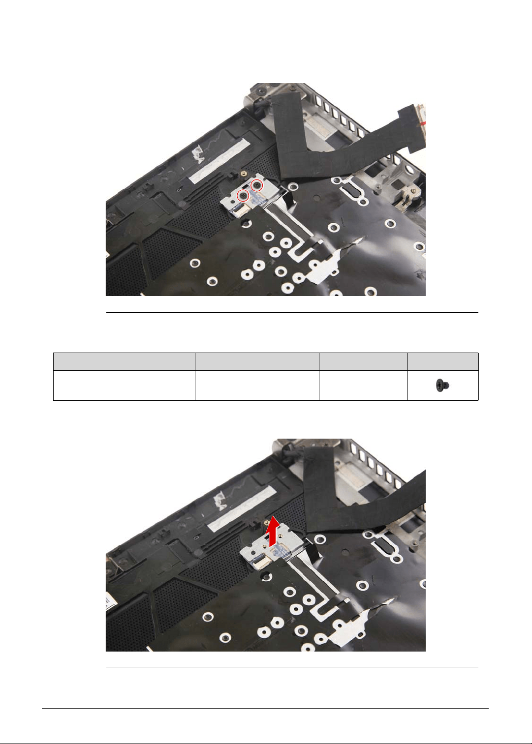
3-30 Machine Maintenance
10. Remove the two screws securing the turbo key module to the upper case.
Figure 3-38. Turbo Key Module Screws
11. Remove the turbo key module from the upper case.
Figure 3-39. Turbo Key Module
Table 3-38. Screws
Step Screw Quantity Torque Screw Type
Turbo Key Module
Disassembly
M2 × L2.5 1 1.6 ± 0.24 kgf cm
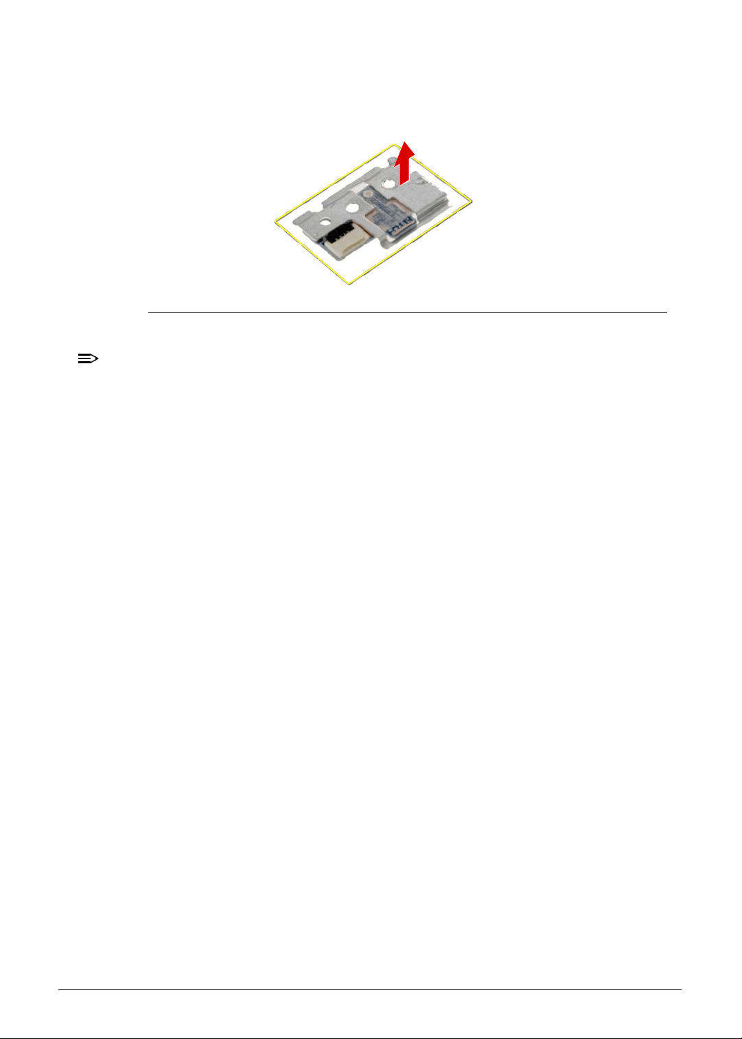
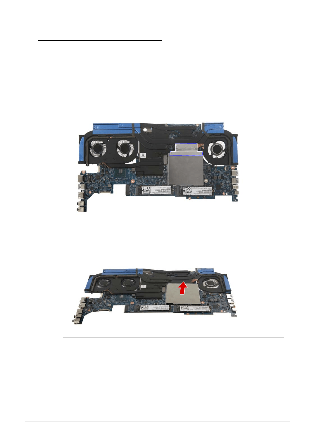
3-32 Machine Maintenance
Removing the Memory Modules 0
1. Perform the Removing the Lower Case procedure described on page 3-9.
2. Perform the Removing the Battery Pack procedure described on page 3-11.
3. Perform the Removing the WLAN Module procedure described on page 3-13.
4. Perform the Removing the RTC Battery procedure described on page 3-15.
5. Perform the Removing the DC-In Cable procedure described on page 3-16.
6. Perform the Removing the Mainboard procedure described on page 3-17.
7. Detach the adhesive tape securing the EMI shielding to the thermal module.
Figure 3-41. EMI Shielding - Adhesive Tape
8. Detach the EMI shielding from the mainboard.
Figure 3-42. Memory Module - EMI Shielding
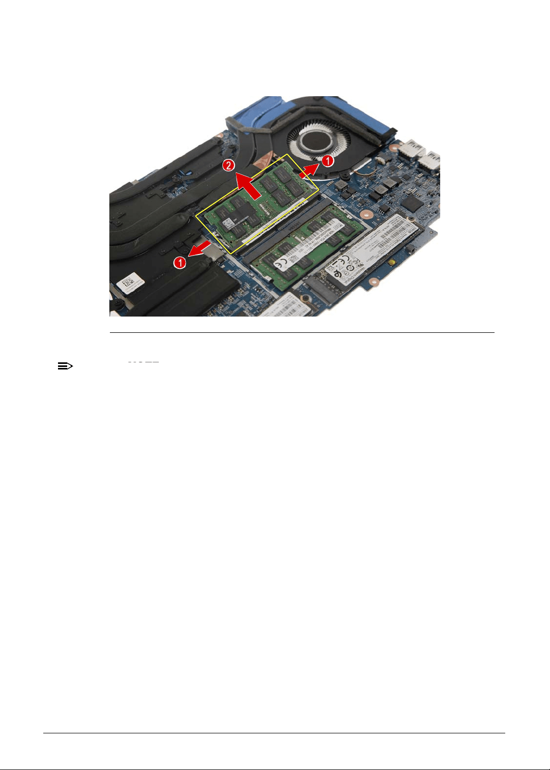
Machine Maintenance 3-33
9. Push out the latches on both sides of the DIMM slot (1) until the memory module tilts
upward, then detach the memory module from the slot (2).
Figure 3-43. Memory Module - DIMM2 Slot
NOTE:
NOTE:
WEEE Annex VII part. A circuit board that is > 10cm
2
has been highlighted with a
yellow rectangle in Figure 3-43. Follow the local regulations for disposing this type of
circuit board.
10. Repeat Step 9 to remove the remaining memory module.
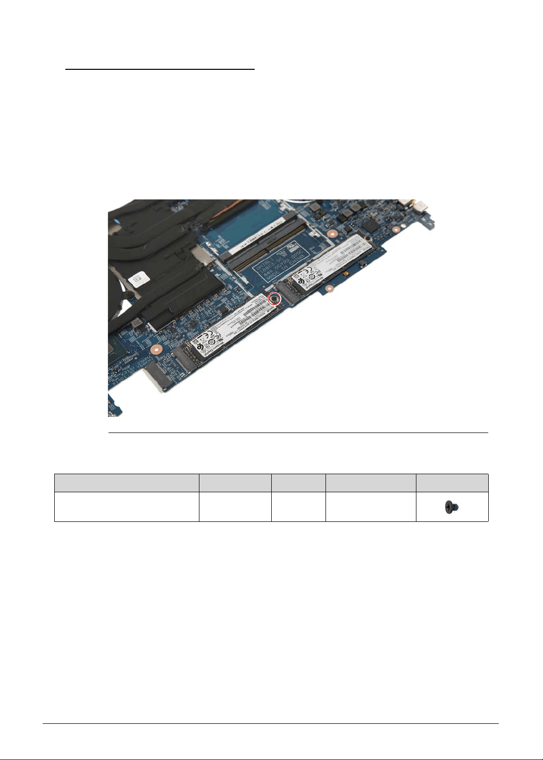
3-34 Machine Maintenance
Removing the SSD Modules 0
1. Perform the Removing the Lower Case procedure described on page 3-9.
2. Perform the Removing the Battery Pack procedure described on page 3-11.
3. Perform the Removing the WLAN Module procedure described on page 3-13.
4. Perform the Removing the RTC Battery procedure described on page 3-15.
5. Perform the Removing the DC-In Cable procedure described on page 3-16.
6. Perform the Removing the Mainboard procedure described on page 3-17.
7. Remove the screw securing the SSD1 module to the mainboard.
Figure 3-44. SSD1 Module Screw
Table 3-44. Screw
Step Screw Quantity Torque Screw Type
SSD1 Module Disassembly M2 × L2.5 1 1.6 ± 0.24 kgf cm
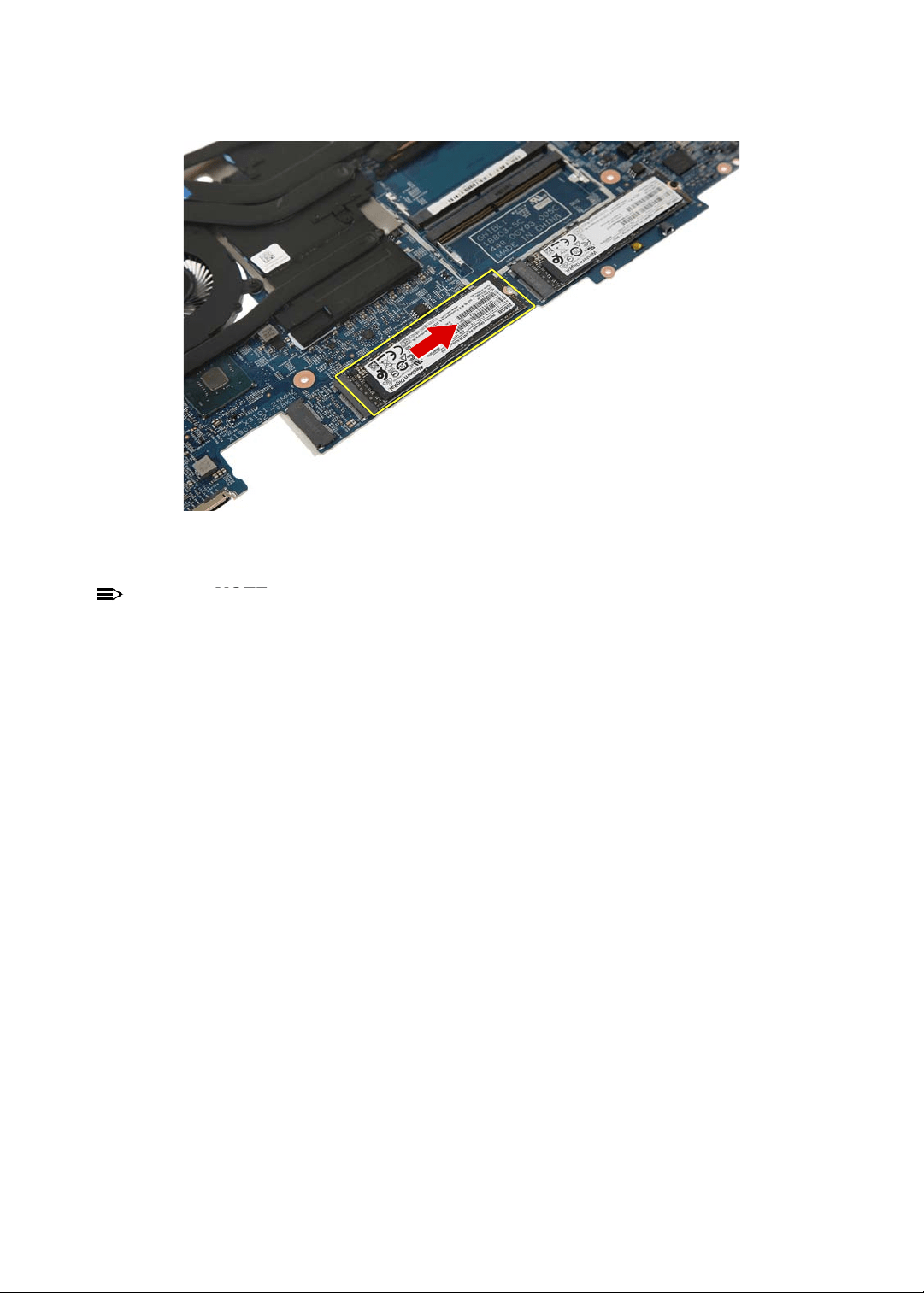
Machine Maintenance 3-35
8. Detach the SSD1 module from the mainboard.
Figure 3-45. SSD1 Module
NOTE:
NOTE:
WEEE Annex VII part. A circuit board that is > 10cm
2
has been highlighted with a
yellow rectangle in Figure 3-45. Follow the local regulations for disposing this type of
circuit board.
9. Repeat Steps 7~8 to remove the SSD2 module.
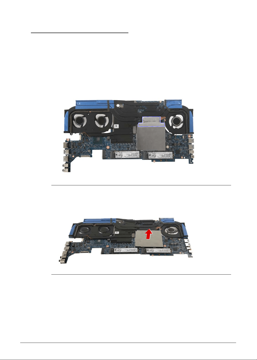
3-36 Machine Maintenance
Removing the Thermal Module 0
1. Perform the Removing the Lower Case procedure described on page 3-9.
2. Perform the Removing the Battery Pack procedure described on page 3-11.
3. Perform the Removing the WLAN Module procedure described on page 3-13.
4. Perform the Removing the RTC Battery procedure described on page 3-15.
5. Perform the Removing the DC-In Cable procedure described on page 3-16.
6. Perform the Removing the Mainboard procedure described on page 3-17.
7. Detach the adhesive tape securing the EMI shielding to the thermal module.
Figure 3-46. EMI Shielding - Adhesive Tape
8. Detach the EMI shielding from the mainboard.
Figure 3-47. Memory Module - EMI Shielding
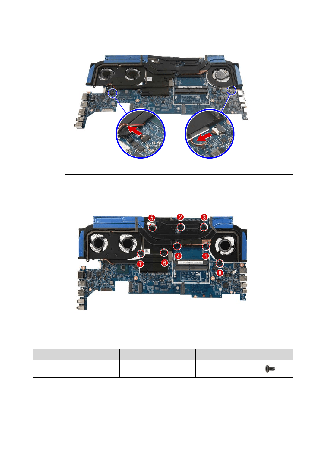
Machine Maintenance 3-37
9. Disconnect the fan cables from the mainboard.
Figure 3-48. Mainboard Connector - Fan Cables
10. Remove the eight screws securing the thermal module to the mainboard.
Figure 3-49. Thermal Module Screws
Table 3-49. Screws
Step Screw Quantity Torque Screw Type
Thermal Module Disassembly M2 × L4 8 1.6 ± 0.24 kgf cm
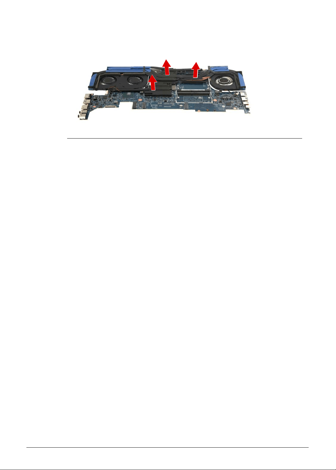
3-38 Machine Maintenance
11. Gently lift the thermal module off the mainboard.
Figure 3-50. Thermal Module
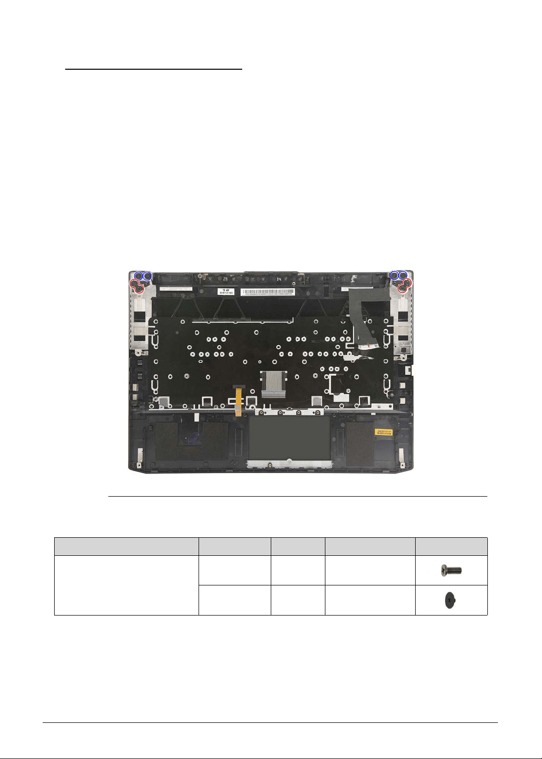
Machine Maintenance 3-39
Removing the Upper Case
0
1. Perform the Removing the Lower Case procedure described on page 3-9.
2. Perform the Removing the Battery Pack procedure described on page 3-11.
3. Perform the Removing the WLAN Module procedure described on page 3-13.
4. Perform the Removing the RTC Battery procedure described on page 3-15.
5. Perform the Removing the DC-In Cable procedure described on page 3-16.
6. Perform the Removing the Mainboard procedure described on page 3-17.
7. Perform the Removing the Touchpad Module procedure described on page 3-23.
8. Perform the Removing the Left and Right Speakers procedure described on page 3-25.
9. Perform the Removing the WLAN Antenna procedure described on page 3-27.
10. Perform the Removing the Turbo Key Module procedure described on page 3-29.
11.
Remove the eight screws securing the upper case to the LCD module.
Figure 3-51.
Upper Case Screws
Table 3-51. Screws
Step Screw Quantity Torque Screw Type
Upper Case Disassembly M2.5 × L6 4 3.0 ± 0.45 kgf cm
M2 × L2 4 1.6 ± 0.24 kgf cm
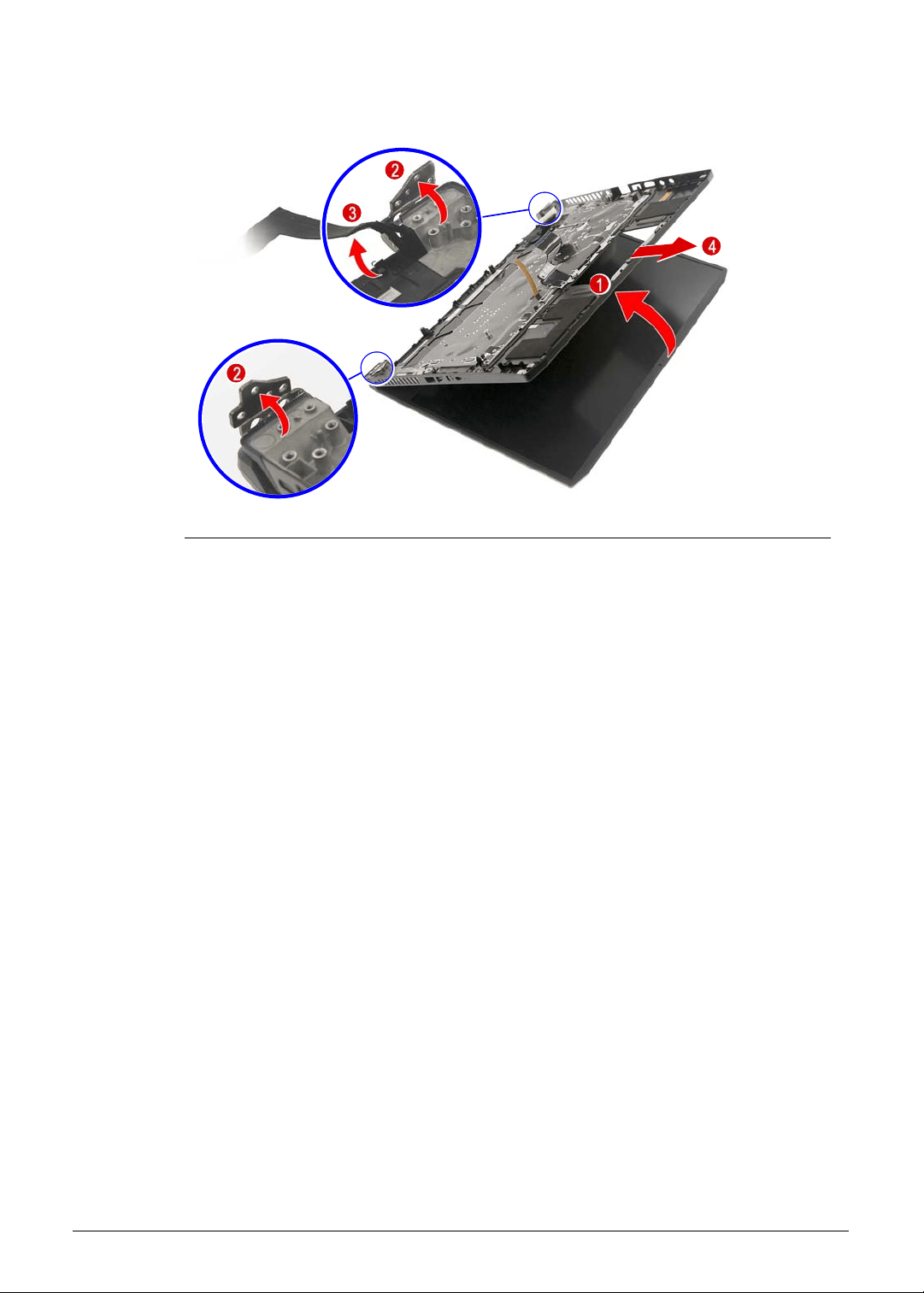
3-40 Machine Maintenance
12. Lift up and remove the upper case from the LCD module.
Figure 3-52. Upper Case
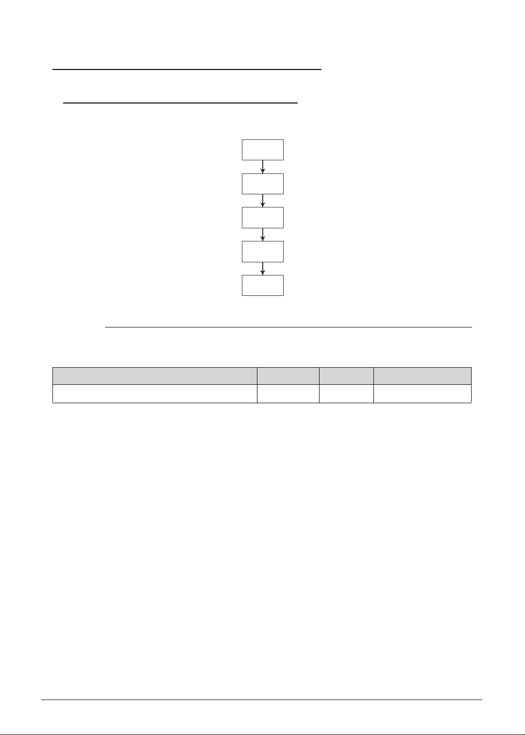
Machine Maintenance 3-41
LCD Module Disassembly Process 0
LCD Module Disassembly Flowchart 0
Figure 3-53. LCD Module Disassembly Flowchart
Table 3-53. Screw List
Step Screw Quantity Acer Part Number
LCD Hinge Brackets Disassembly M2.5 x L2.5 6 86.9AR13.2R5
LCD
MODULE
CAMERA
MODULE
LCD
BEZEL
LCD
PANEL
LCD HINGE
BRACKETS
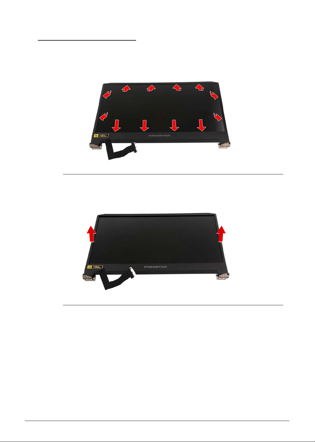
3-42 Machine Maintenance
Removing the LCD Bezel 0
1. Perform the Removing the Upper Case procedure described on page 3-39.
2. Carefully pry loose the LCD bezel from the LCD back cover. Start on the bottom side,
continue to the left and right sides, and finally the top side.
Figure 3-54. LCD Bezel Latches
3. Detach the LCD bezel from the LCD back cover.
Figure 3-55. LCD Bezel
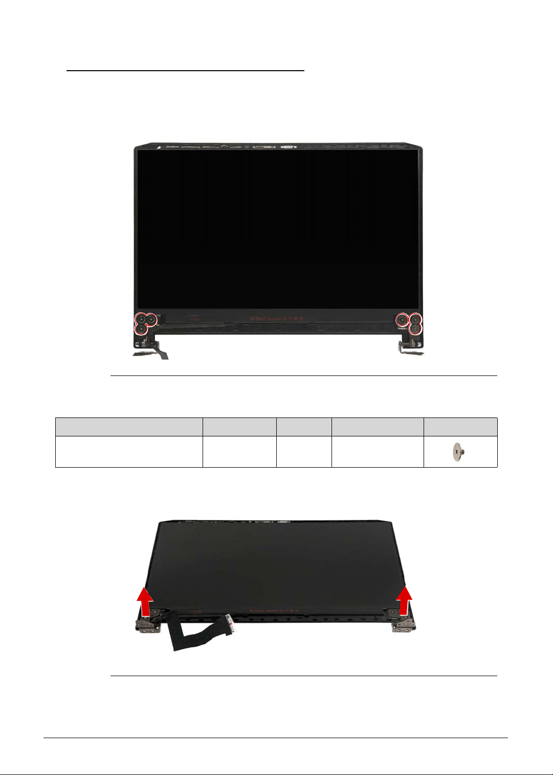
Machine Maintenance 3-43
Removing the LCD Hinge Brackets 0
1. Perform the Removing the Upper Case procedure described on page 3-39.
2. Perform the Removing the LCD Bezel procedure described on page 3-42.
3. Remove the six screws securing the left and right LCD hinge brackets to the LCD panel.
Figure 3-56. LCD Hinge Brackets Screws
4. Lift up and remove the LCD hinge brackets.
Figure 3-57. LCD Hinge Brackets
Table 3-56. Screws
Step Screw Quantity Torque Screw Type
LCD Hinge Brackets
Disassembly
M2.5 × L2.5 6 3.0 ± 0.45 kgf cm
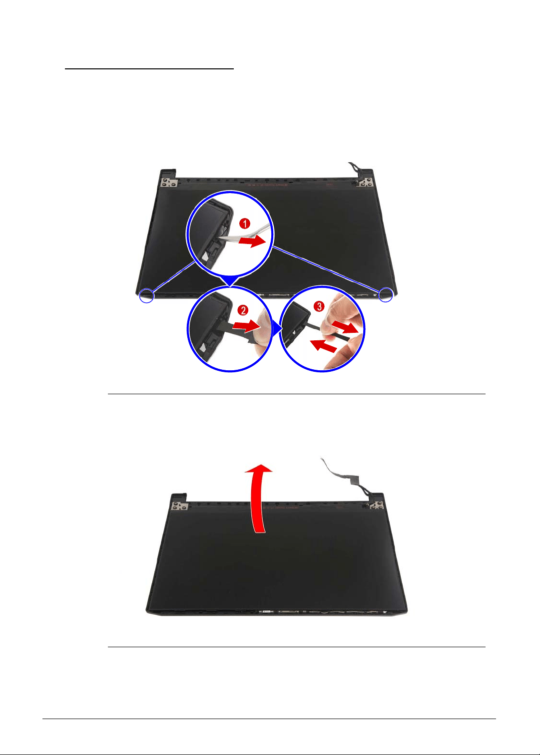
3-44 Machine Maintenance
Removing the LCD Panel 0
1. Perform the Removing the Upper Case procedure described on page 3-39.
2. Perform the Removing the LCD Bezel procedure described on page 3-42.
3. Perform the Removing the LCD Hinge Brackets procedure described on page 3-43.
4. Use a tweezer to grab the pull tab then slowly pull the adhesive tape while maintaining
constant tension until the tape you have completely removed the tape.
Figure 3-58. Double Sided Adhesive Tapes
5. Gently lift the LCD panel from the LCD back cover and then turn it over.
Figure 3-59. LCD Panel
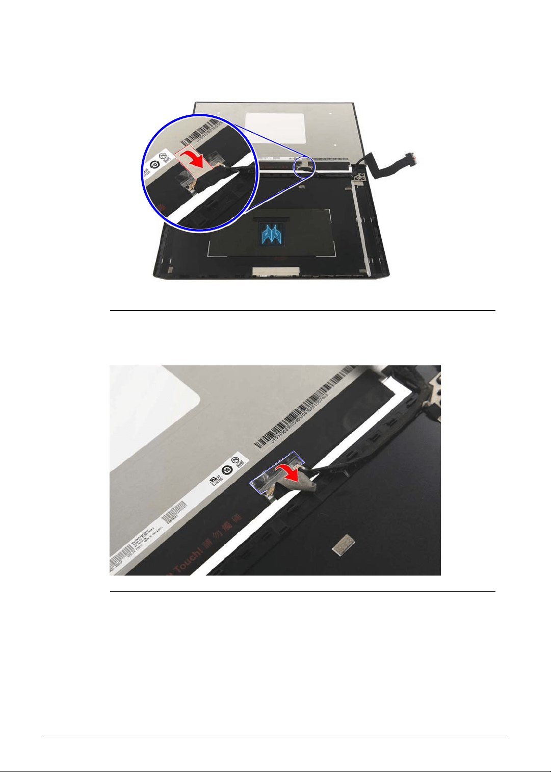
Machine Maintenance 3-45
6. Release the eDP cable from the adhesive tape securing it to the LCD panel.
Figure 3-60. eDP Cable Adhesive Tape
7. Release the eDP cable from the transparent adhesive tape securing it to the LCD panel.
Figure 3-61. eDP Cable Transparent Adhesive Tape
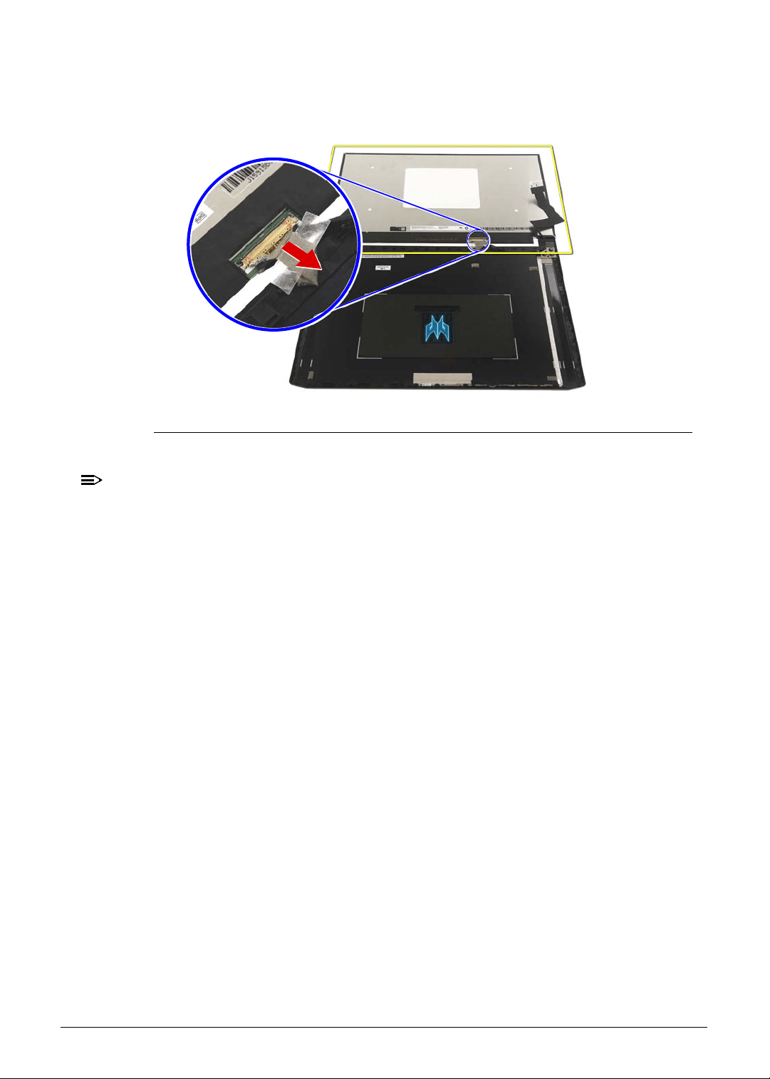
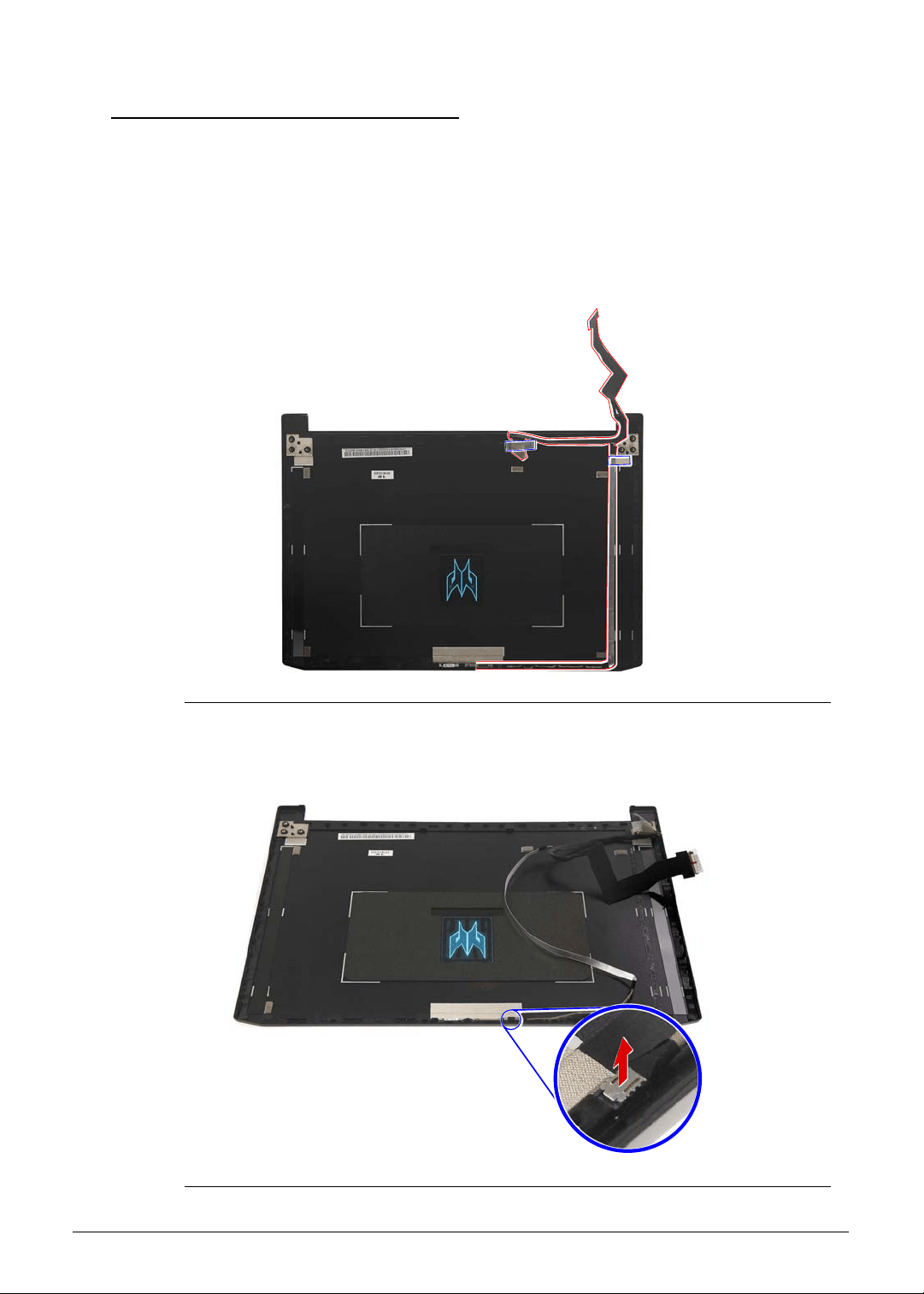
Machine Maintenance 3-47
Removing the Camera Module 0
1. Perform the Removing the Upper Case procedure described on page 3-39.
2. Perform the Removing the LCD Bezel procedure described on page 3-42.
3. Perform the Removing the LCD Hinge Brackets procedure described on page 3-43.
4. Perform the Removing the LCD Panel procedure described on page 3-44.
5. Release the eDP cable from the cable guides and adhesive tapes securing it to the LCD
cover.
Figure 3-63. eDP Cable
6. Disconnect the eDP cable from the camera module.
Figure 3-64. Camera Connector - eDP Cable
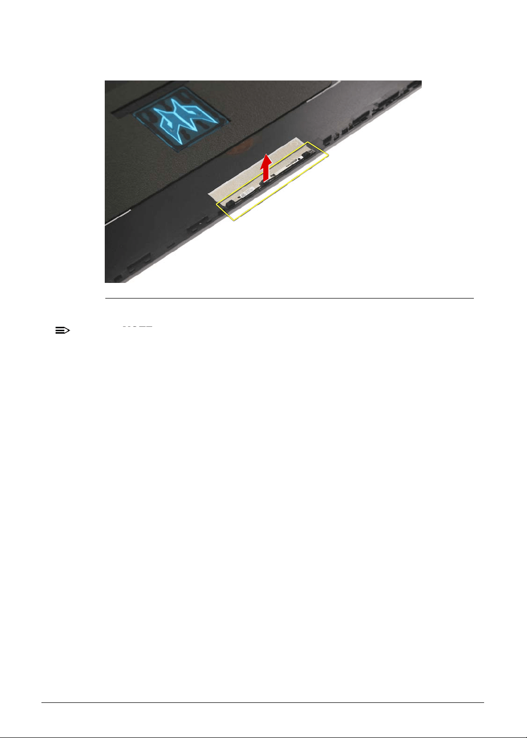
3-48 Machine Maintenance
7. Carefully pry the camera module off the LCD back cover.
Figure 3-65. Camera Module
NOTE:
NOTE:
WEEE Annex VII part. A circuit board that is > 10cm
2
has been highlighted with a
yellow rectangle in Figure 3-65. Follow the local regulations for disposing this type of
circuit board.
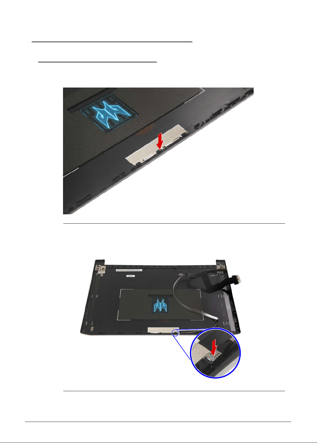
Machine Maintenance 3-49
LCD Module Reassembly Process 0
Replacing the Camera Module 0
1. Attach a double-sided adhesive tape on the back side of the camera module. Position the
camera module on the LCD back cover and press down to secure it in place.
Figure 3-66. Camera Module
2. Connect the eDP cable to the module.
Figure 3-67. Camera Connector - eDP Cable
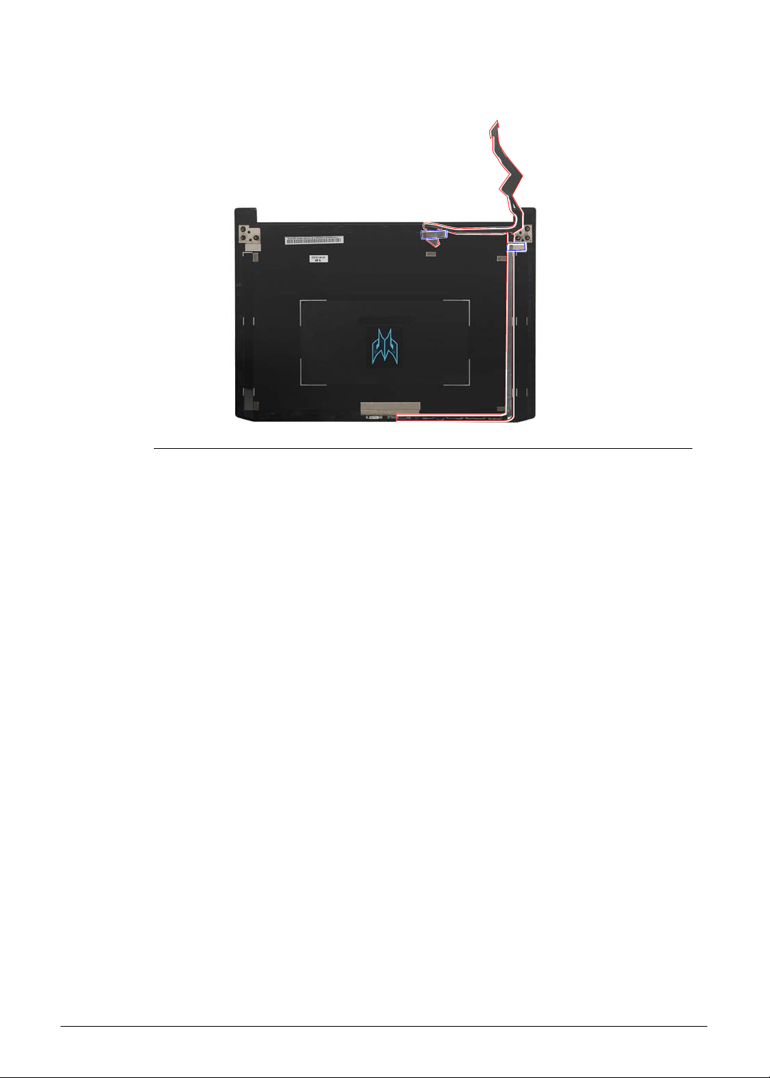
3-50 Machine Maintenance
3. Use the cable guides and adhesive tapes to secure the eDP cable to the LCD cover.
Figure 3-68. eDP Cable
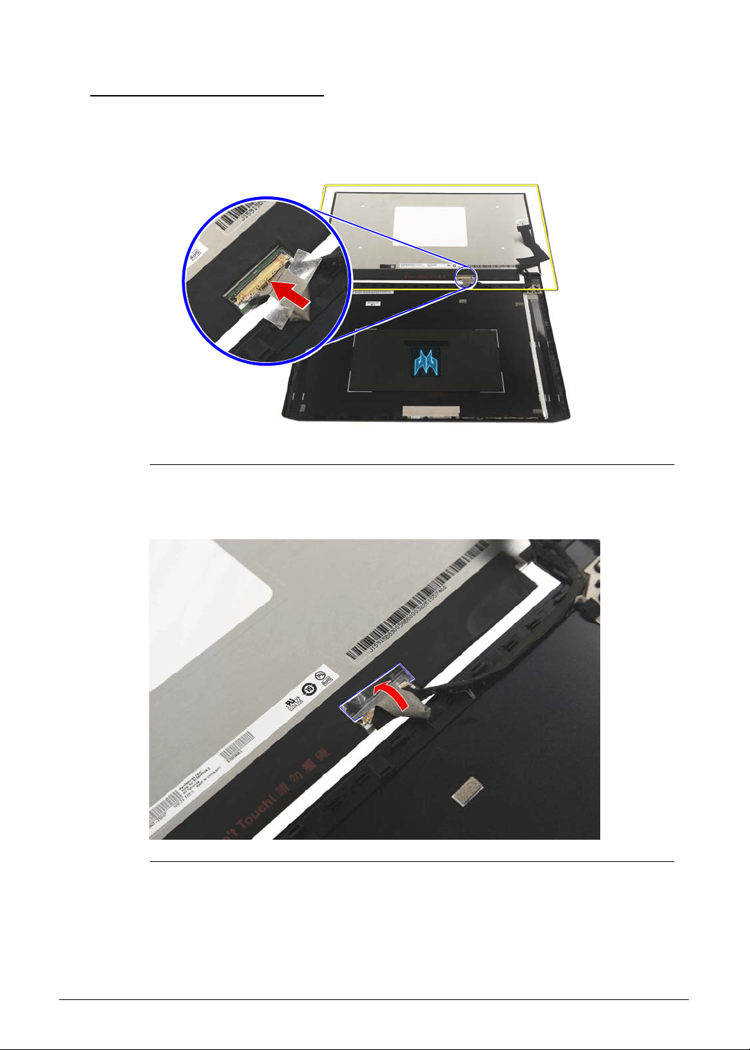
Machine Maintenance 3-51
Replacing the LCD Panel 0
1. Connect the eDP cable to the LCD panel.
Figure 3-69. LCD Panel Connector - eDP Cable
2. Use transparent adhesive tape to secure the eDP cable to the LCD panel.
Figure 3-70. eDP Cable Transparent Adhesive Tape
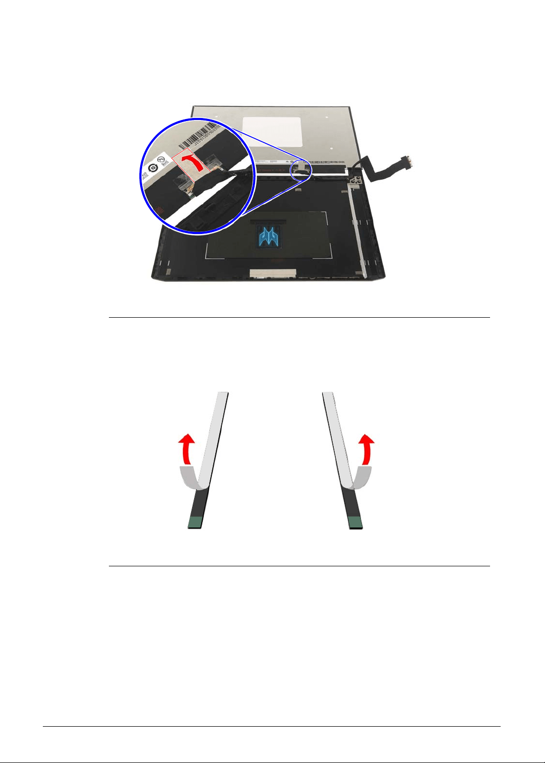
3-52 Machine Maintenance
3. Use adhesive tape to secure the eDP cable to the LCD panel.
Figure 3-71. eDP Cable Adhesive Tape
4. Remove the white strip cover from the double sided adhesive tapes.
Figure 3-72. Double Sided Adhesive Tapes - White Strip Cover
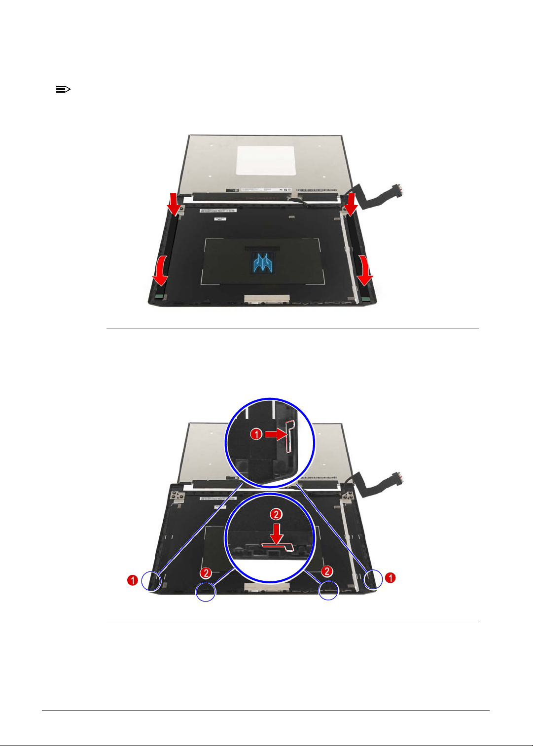
Machine Maintenance 3-53
5. Place the double sided adhesive tapes into the LCD panel cover as shown and press
them down until they stick into place.
NOTE:
NOTE:
Make sure that the non-stick pull tab is located at the top of the LCD panel cover.
Figure 3-73. LCD Panel - Double Sided Adhesive Tapes
6. Align and install the four mylar gaskets to the top of the panel frame on the LCD panel
cover, as shown. Note that the gasket tabs should be facing upwards.
Figure 3-74. Mylar Gaskets
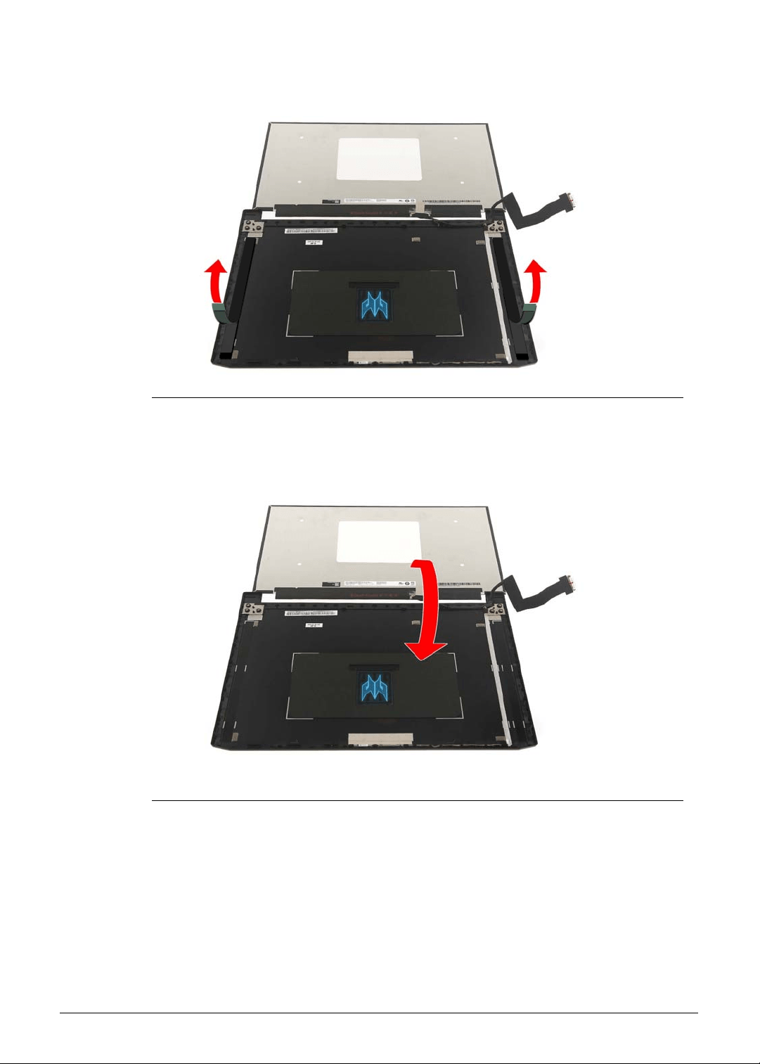
3-54 Machine Maintenance
7. Remove the thin blue strip cover from the double sided adhesive tapes.
Figure 3-75. Double Sided Adhesive Tapes - Thin Blue Strip Cover
8. Gently place the LCD panel into the LCD back cover.
Figure 3-76. LCD Panel
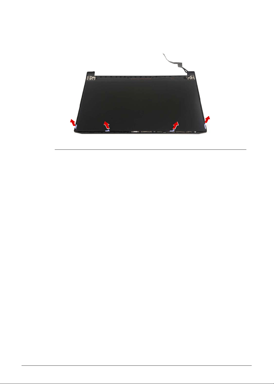
Machine Maintenance 3-55
9. After the LCD panel installation is complete, remove the four mylar gaskets from the LCD
panel cover.
Figure 3-77. Mylar Gaskets
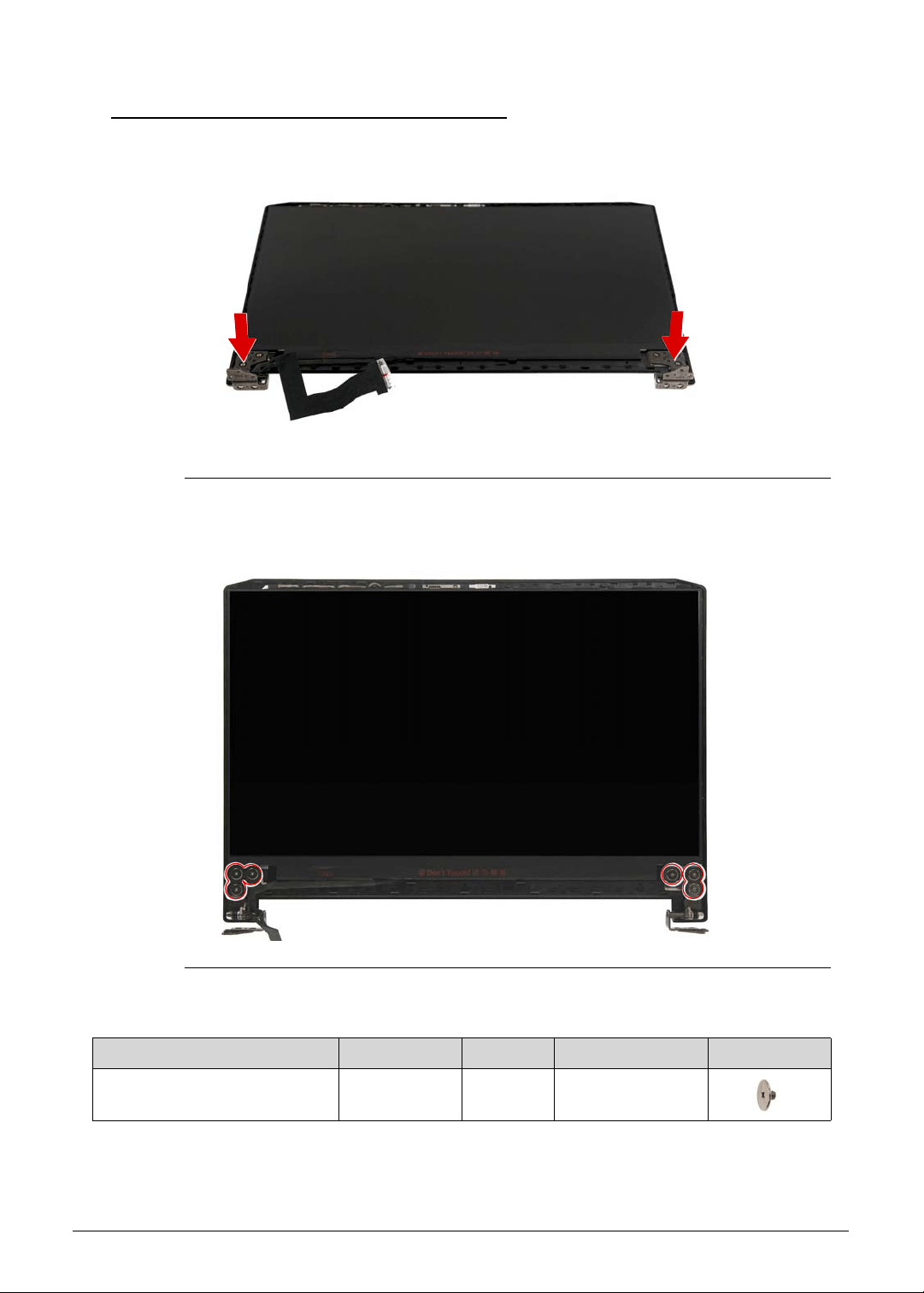
3-56 Machine Maintenance
Replacing the LCD Hinge Brackets 0
1. Attach the left and right LCD hinge brackets to the LCD back cover.
Figure 3-78. LCD Hinge Brackets
2. Secure the left and right LCD hinge brackets to the LCD back cover using six screws.
Figure 3-79. LCD Hinge Brackets Screws
Table 3-79. Screws
Step Screw Quantity Torque Screw Type
LCD Hinge Brackets
Reassembly
M2.5 × L2.5 6 3.0 ± 0.45 kgf cm
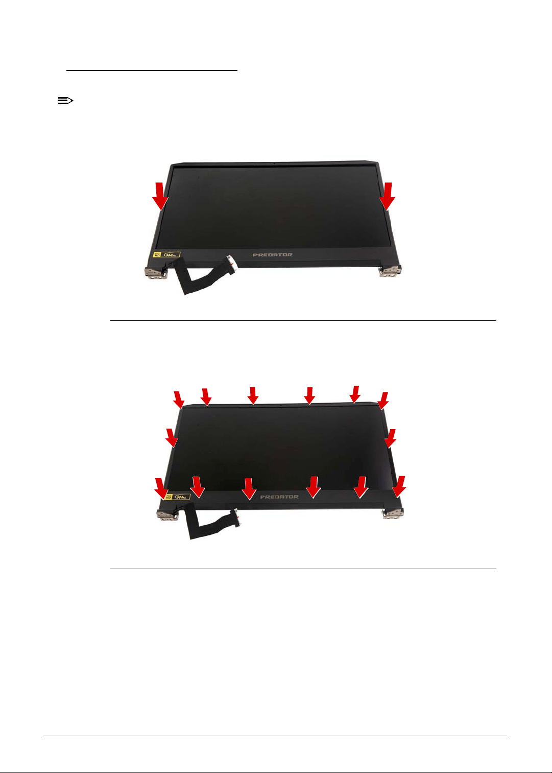
Machine Maintenance 3-57
Replacing the LCD Bezel 0
1. Place the bezel on top of the LCD panel.
NOTE:
NOTE:
Make sure that the eDP cable is properly routed on the left hinge side and there is no
gap between the bezel and the back cover.
Figure 3-80. LCD Bezel
2. Press the bezel on all sides until it snaps into place.
Figure 3-81. LCD Bezel Latches
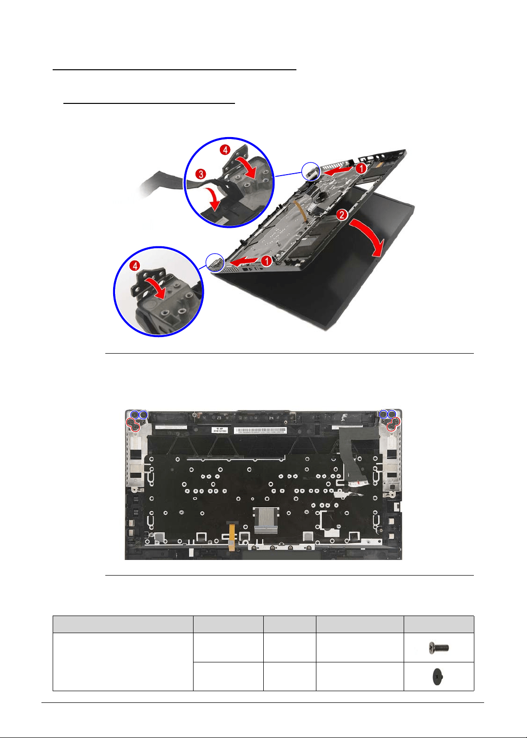
3-58 Machine Maintenance
Main Unit Reassembly Process 0
Replacing the Upper Case 0
1. Place the upper case into the LCD module.
Figure 3-82. Upper Case
2. Secure the upper case to the LCD module using four screws.
Figure 3-83.
Upper Case Screws
Table 3-83. Screws
Step Screw Quantity Torque Screw Type
Upper Case Reassembly M2.5 × L6 4 3.0 ± 0.45 kgf cm
M2 × L2 4 1.6 ± 0.24 kgf cm
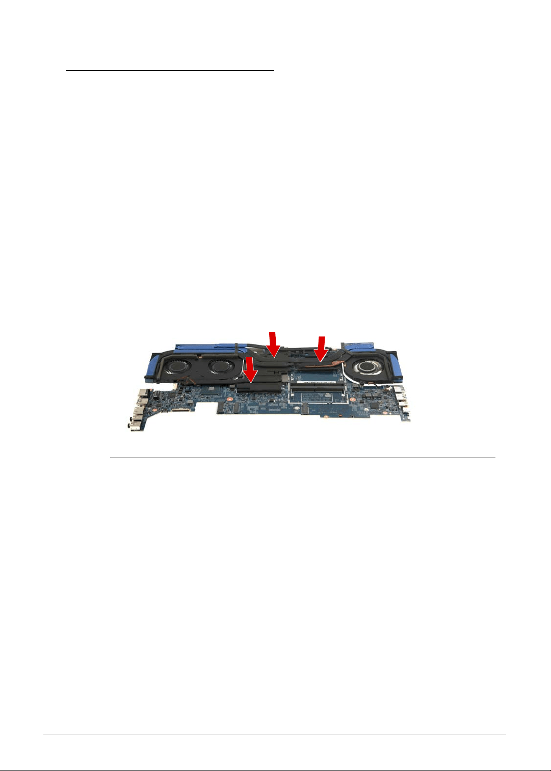
Machine Maintenance 3-59
Replacing the Thermal Module 0
IMPORTANT:
+
Make sure all thermal pads for the mainboard chipsets and VRAMs are in
place before replacing the thermal module.
1. Use a lint-free cloth or cotton swab soaked in isopropyl alcohol or acetone to remove all
traces of thermal grease from the contact surfaces on both the heatsink module and the
CPU.
2. Apply a small amount of thermal grease onto the center area of the CPU and GPU.
There is no need to spread the grease manually, the force used during the installation of
the thermal module is sufficient. The following brands of thermal grease are approved for
use:
N302 I-Connosseur
Honeywell
Eapus XR-PE
3. Place the thermal module on the mainboard. Make sure to align the screw hole on the
thermal module with the screw hole on the mainboard. Keep the module as level as
possible to spread the thermal grease evenly.
Figure 3-84. Thermal Module
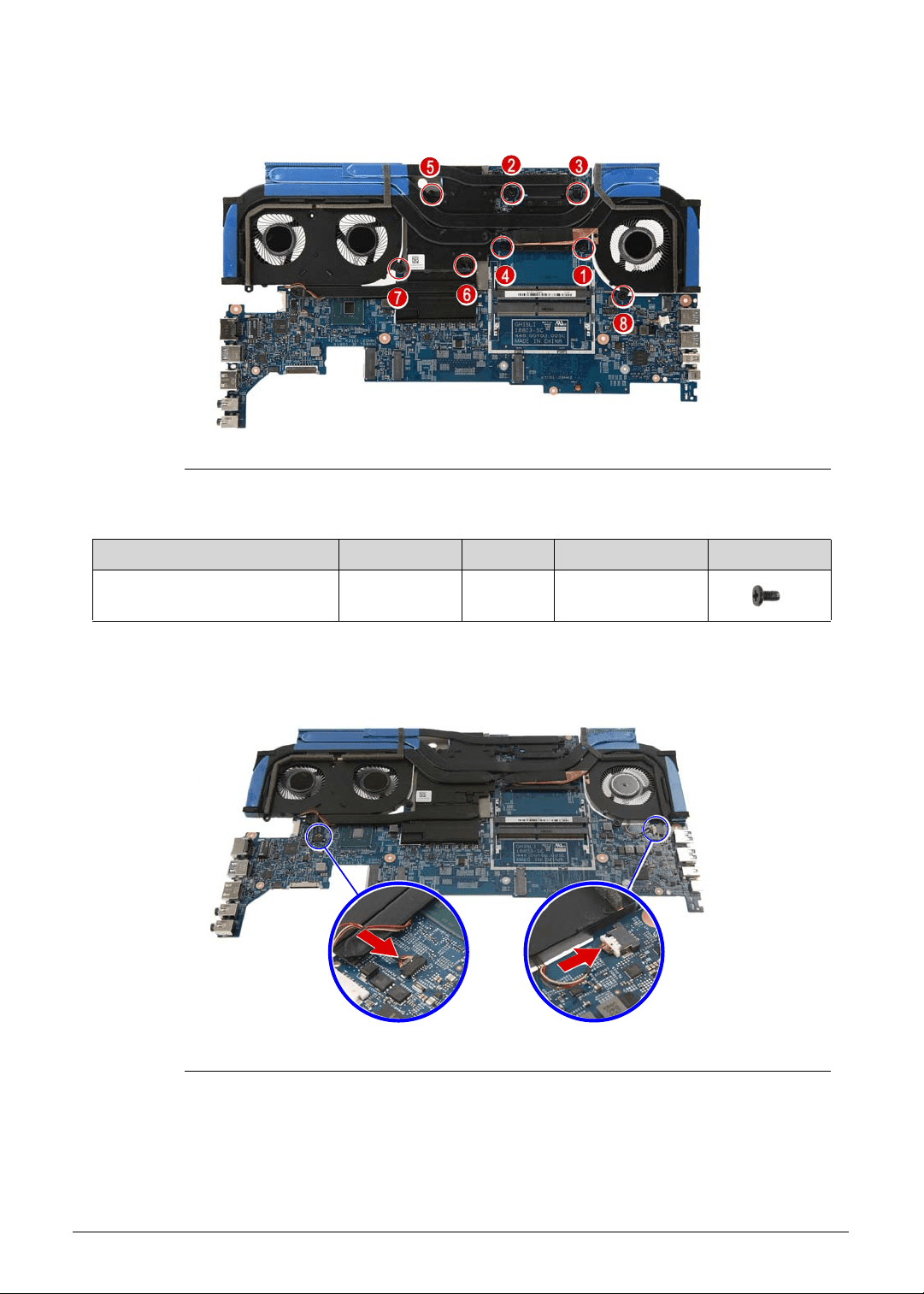
3-60 Machine Maintenance
4. Secure the thermal module to the mainboard using eight screws.
Figure 3-85. Thermal Module Screws
5. Connect the fan cables to the mainboard.
Figure 3-86. Mainboard Connector - Fan Cables
Table 3-85. Screws
Step Screw Quantity Torque Screw Type
Thermal Module Reassembly M2 × L4 8 1.6 ± 0.24 kgf cm
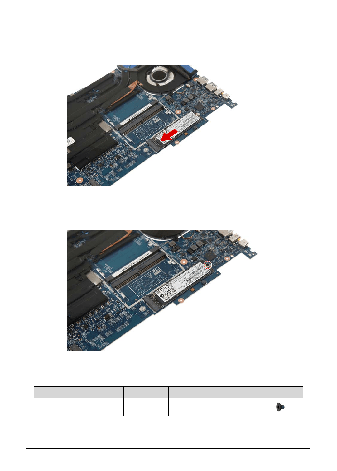
Machine Maintenance 3-61
Replacing the SSD Modules 0
1. Place the SSD2 module into the mainboard.
Figure 3-87. SSD2 Module
2. Secure the SSD2 module to the mainboard using one screw.
Figure 3-88. SSD2 Module Screw
3. Repeat Steps 1~2 to replace the SSD1 module.
Table 3-88. Screw
Step Screw Quantity Torque Screw Type
SSD2 Module Reassembly M2 × L2.5 1 1.6 ± 0.24 kgf cm
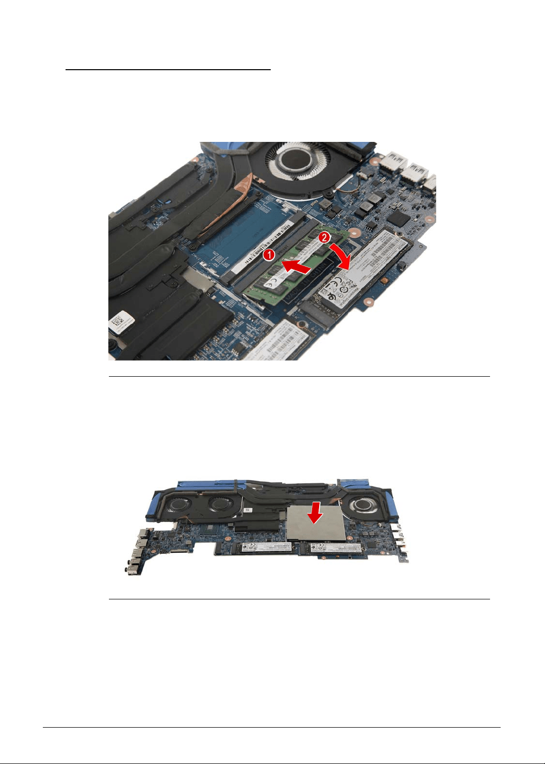
3-62 Machine Maintenance
Replacing the Memory Module 0
1. Insert the memory module at a 30° angle into the DIMM slot (1) and then press it down (2)
until it locks into place.
The module is keyed so it can only be inserted in one direction. If the module does not fit,
make sure that the notch in the module lines up with the tab in the memory slot.
Figure 3-89. Memory Module - DIMM1 Slot
2. Repeat Step 1 to install the remaining memory module.
3. Use the EMI shielding to cover the memory modules.
Figure 3-90. Memory Module - EMI Shielding
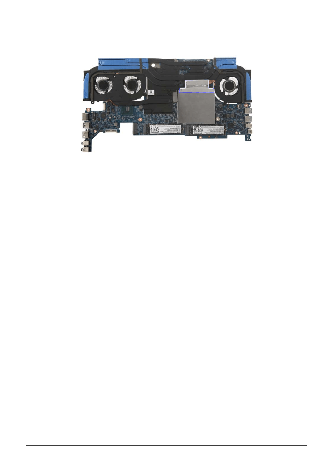
Machine Maintenance 3-63
4. Use adhesive tape to secure the EMI shielding to the thermal module.
Figure 3-91. EMI Shielding - Adhesive Tape
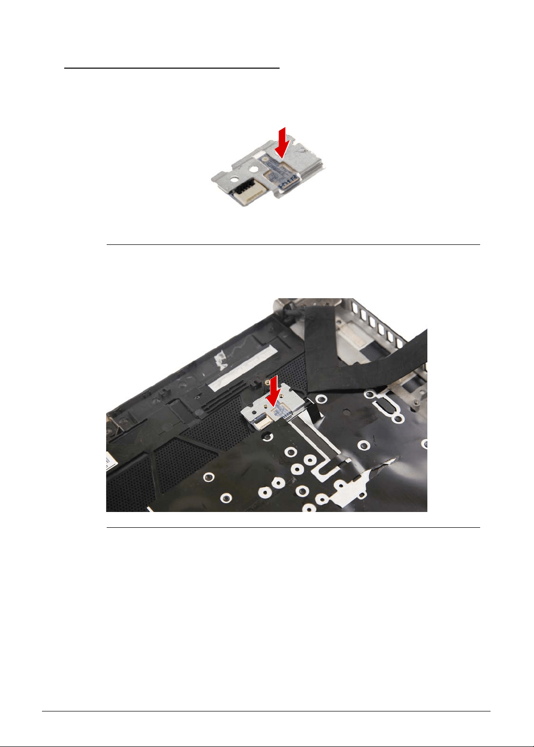
3-64 Machine Maintenance
Replacing the Turbo Key Module 0
1. Use double sided tape to secure the bracket to the turbo key module.
Figure 3-92. Turbo Key Bracket
2. Place the turbo key module into the upper case.
Figure 3-93. Turbo Key Module
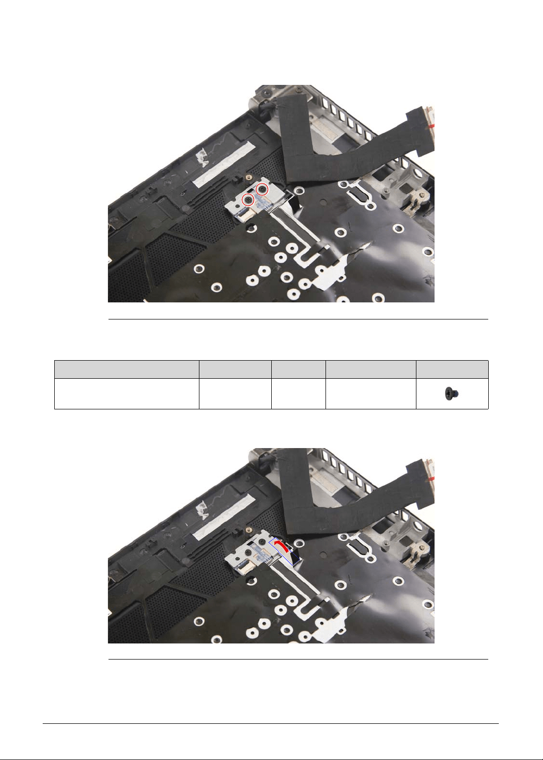
Machine Maintenance 3-65
3. Use two screws to secure the turbo key module to the upper case.
Figure 3-94. Turbo Key Module Screws
4. Use adhesive tape to secure the turbo key module to the upper case.
Figure 3-95. Turbo Key Module - Adhesive Tape
Table 3-94. Screws
Step Screw Quantity Torque Screw Type
Turbo Key Module
Reassembly
M2 × L2.5 1 1.6 ± 0.24 kgf cm
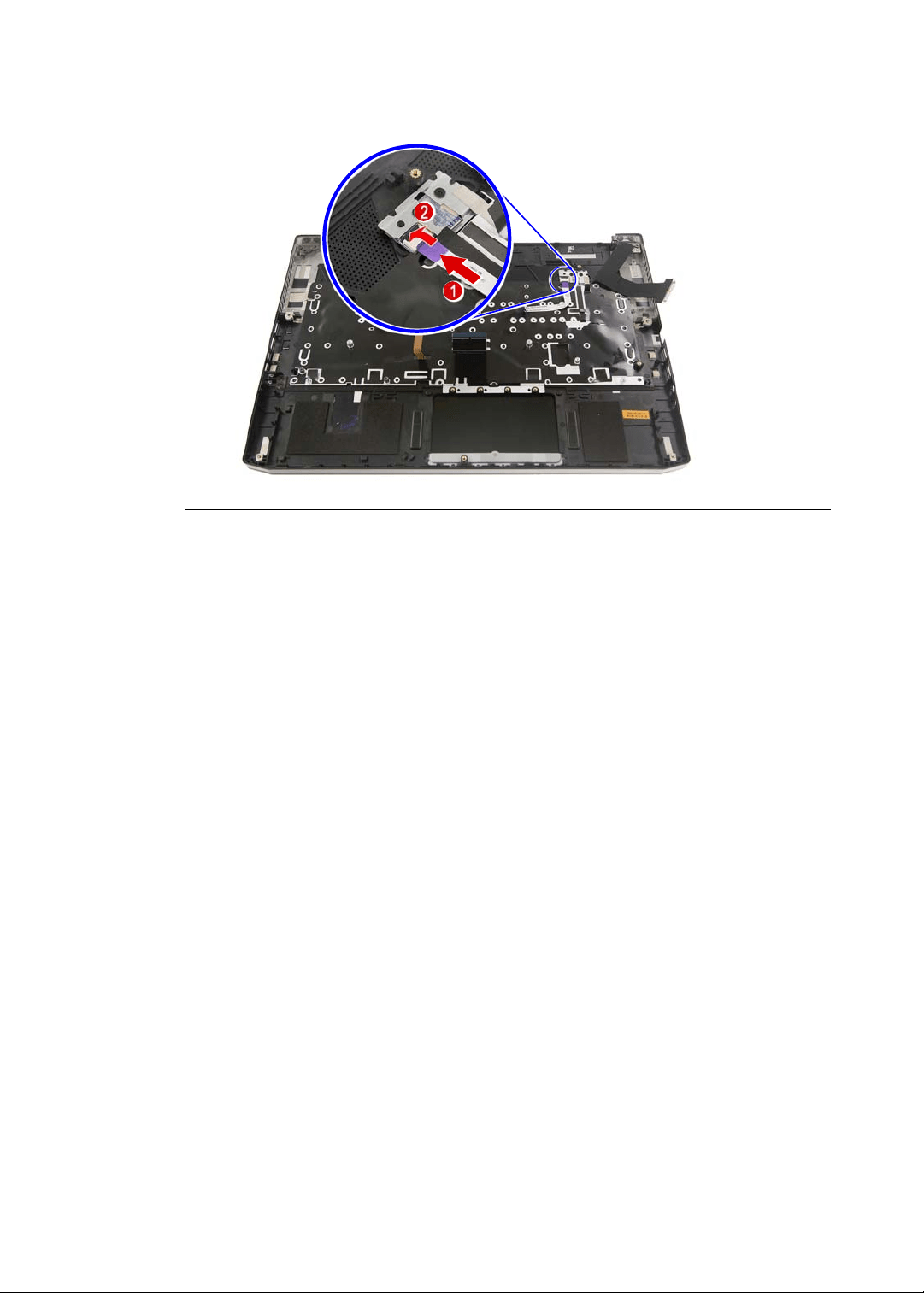
3-66 Machine Maintenance
5. Connect the cable to the turbo key module.
Figure 3-96. Turbo Key Connector - Turbo Key Cable
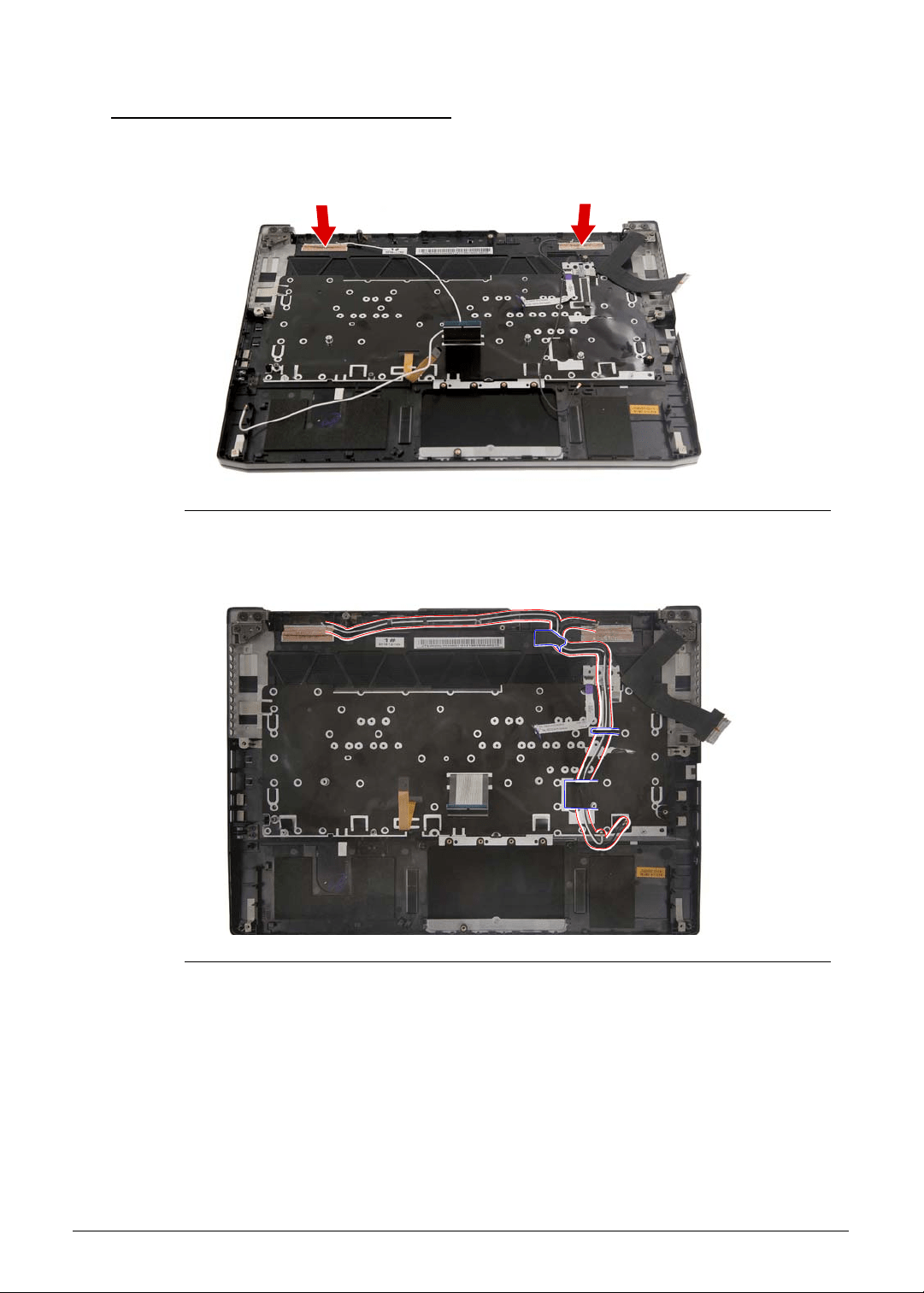
Machine Maintenance 3-67
Replacing the WLAN Antenna 0
1. Place the WLAN antenna into the upper case and press them down until they stick into
place.
Figure 3-97. WLAN Antenna
2. Use the adhesive tapes and cable guides of the upper case to secure the antenna cables.
Figure 3-98. Upper Case Adhesive Tapes and Cable Guides - Antenna Cables
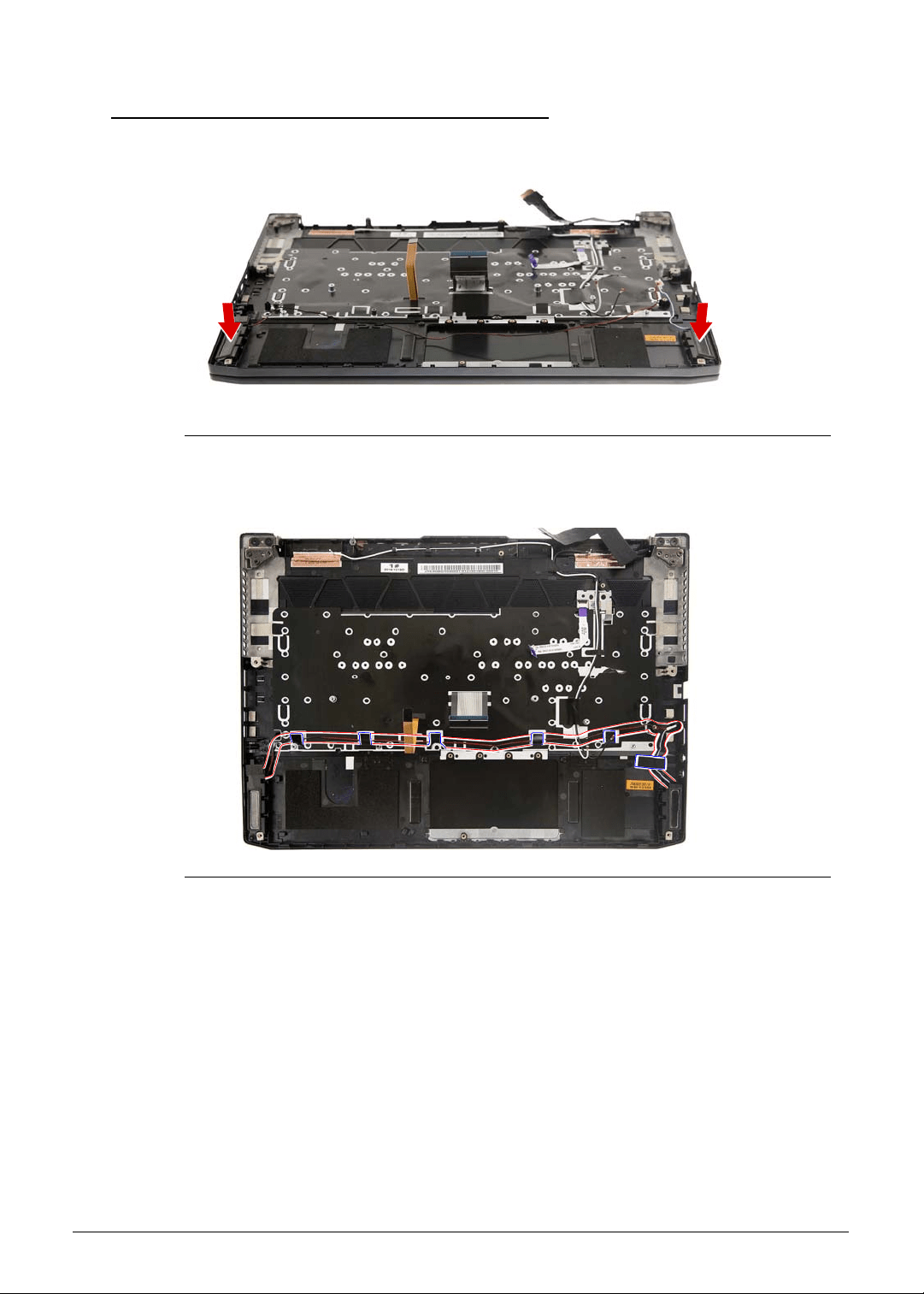
3-68 Machine Maintenance
Replacing the Left and Right Speakers 0
1. Place the left and right speakers into their sockets.
Figure 3-99. Left and Right Speakers
2. Use the adhesive tapes and cable guides to secure the speaker cables to the upper case.
Figure 3-100. Upper Case Adhesive Tapes and Cable Guides - Speaker Cables
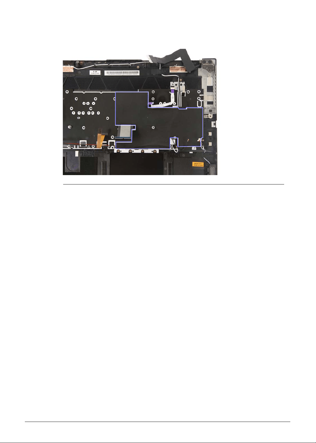
Machine Maintenance 3-69
3. Place the mylar into the upper case as shown and press it down until it sticks into place.
Figure 3-101. Upper Case Mylar - Speaker Cable
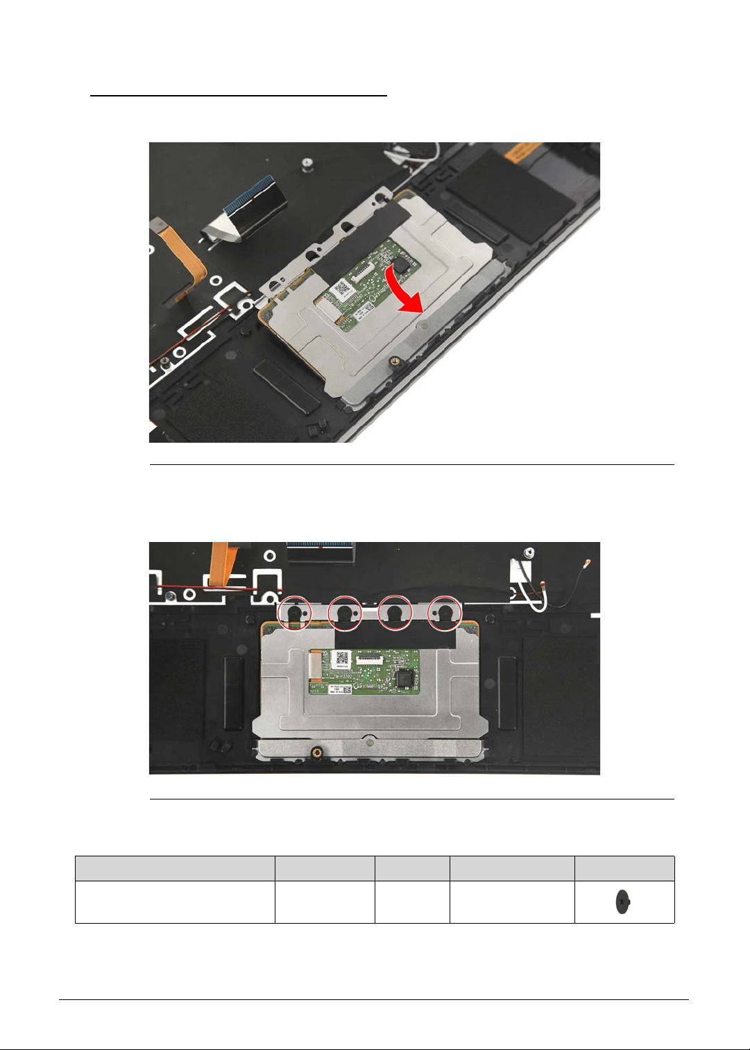
3-70 Machine Maintenance
Replacing the Touchpad Module 0
1. Insert the touchpad module into the upper case.
Figure 3-102. Touchpad Module
2. Use four screws to secure the touchpad module to the upper case.
Figure 3-103. Touchpad Module Screws
Table 3-103. Screws
Step Screw Quantity Torque Screw Type
Touchpad Module
Reassembly
M2 × L2 4 1.6 ± 0.24 kgf cm
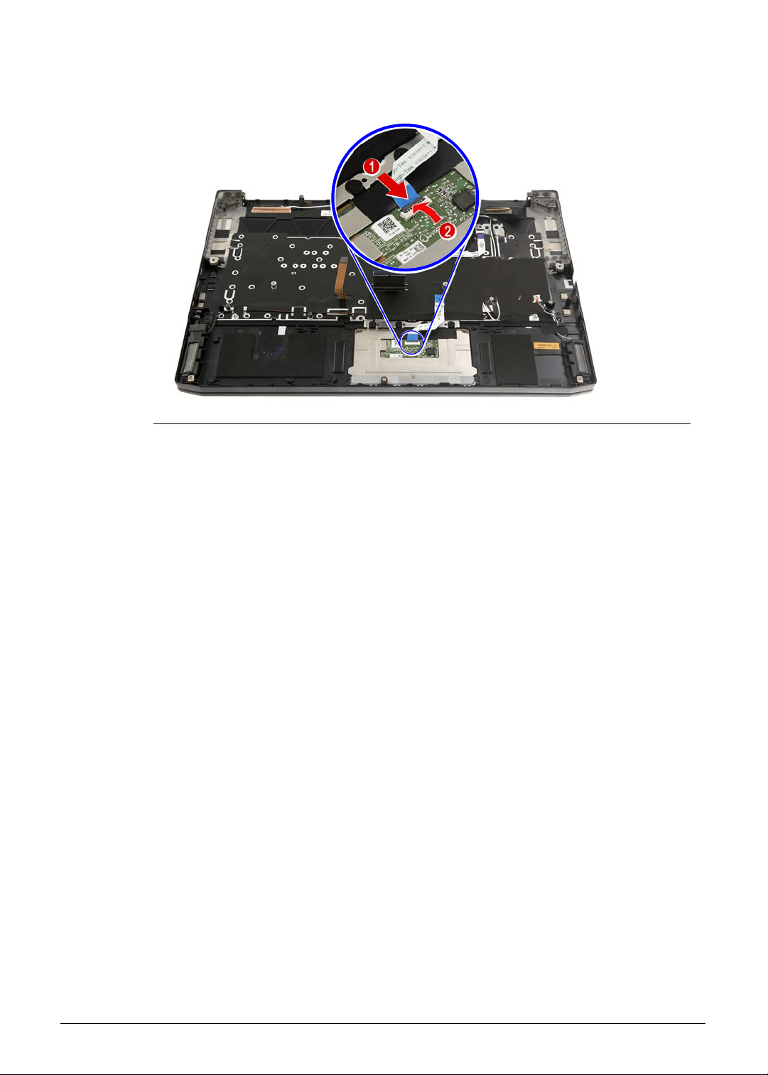
Machine Maintenance 3-71
3. Connect the touchpad cable to the touchpad module.
Figure 3-104. Touchpad Connector - Touchpad Cable
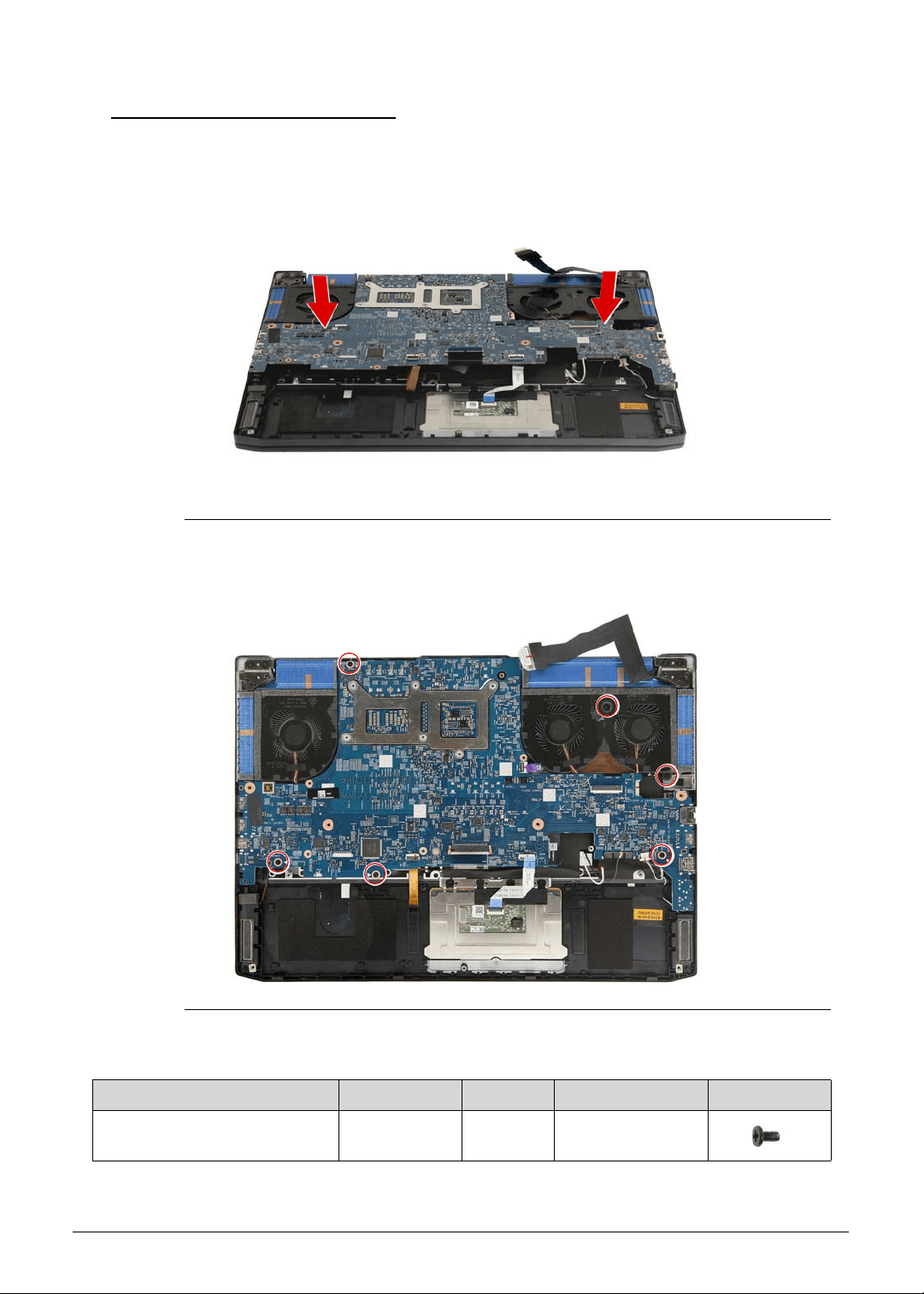
3-72 Machine Maintenance
Replacing the Mainboard 0
1. Slide the mainboard into the upper case, making sure the I/O ports of the mainboard are
extruding from their port holes, and that the turbo key cable, eDP cable, WLAN antenna
cables, touchpad cable, speaker cable, keyboard cable and keyboard backlight cable are
accessible for reconnection to their respective connectors.
Figure 3-105. Mainboard
2. Use six screws to secure the mainboard to the upper case.
Figure 3-106. Mainboard Screws
Table 3-106. Screws
Step Screw Quantity Torque Screw Type
Mainboard Reassembly M2 × L4 6 1.6 ± 0.24 kgf cm
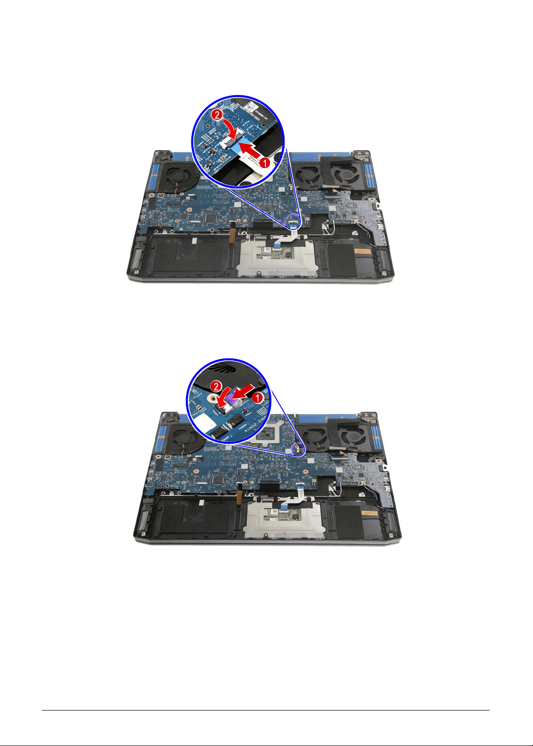
Machine Maintenance 3-73
3. Connect the touchpad cable to the mainboard.
Figure 3-107. Mainboard Connector - Touchpad Cable
4. Connect the turbo key cable to the mainboard.
Figure 3-108. Mainboard Connector - Turbo Key Cable
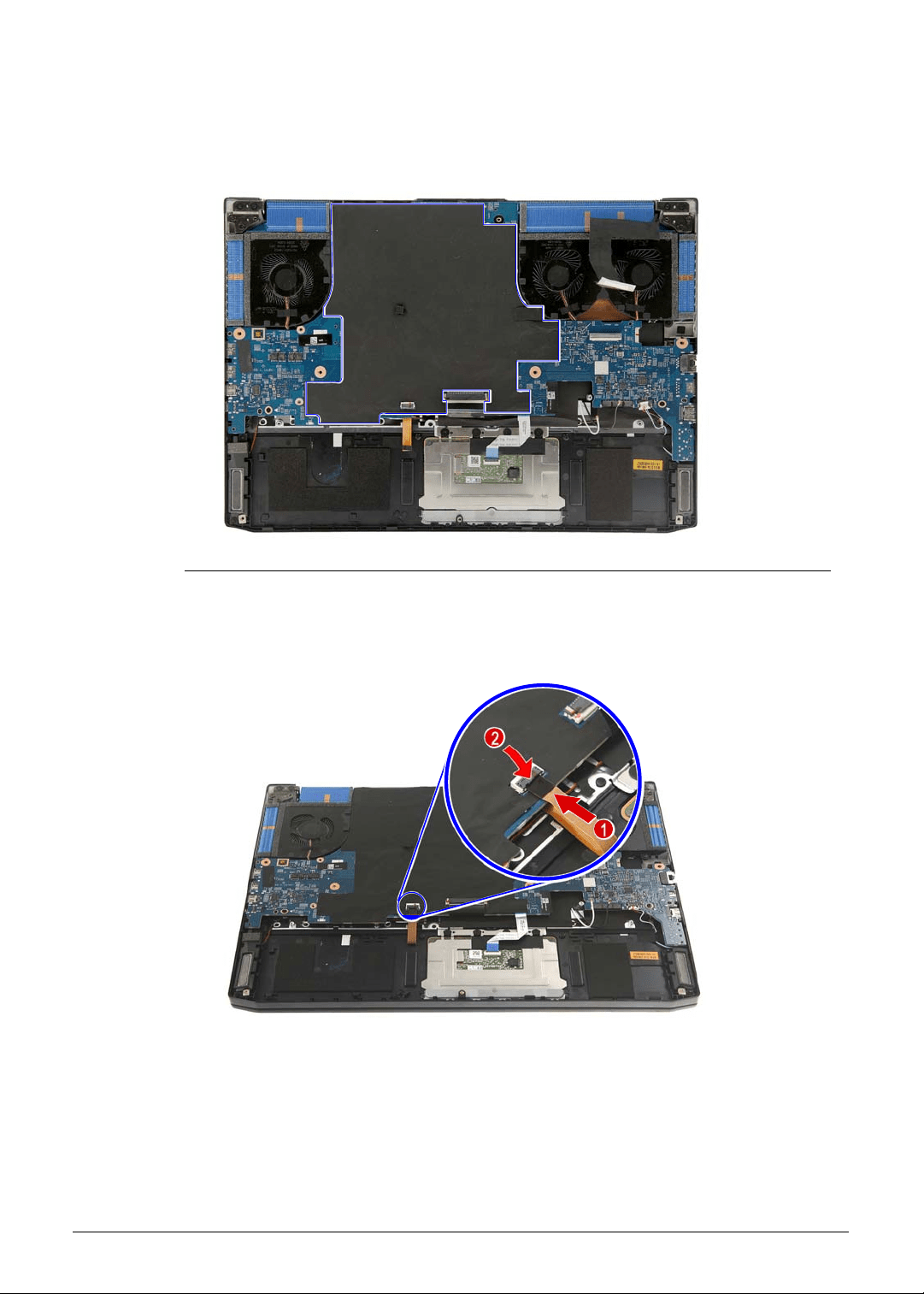
3-74 Machine Maintenance
5. Place the mylar into the mainboard as shown and press it down until it sticks into place.
Make sure that the keyboard cable and keyboard backlight cable are accessible for
reconnection to their respective connectors.
Figure 3-109. Mainboard Mylar
6. Connect the keyboard backlight cable to the mainboard.
Figure 3-110. Mainboard Connector - Keyboard Backlight Cable
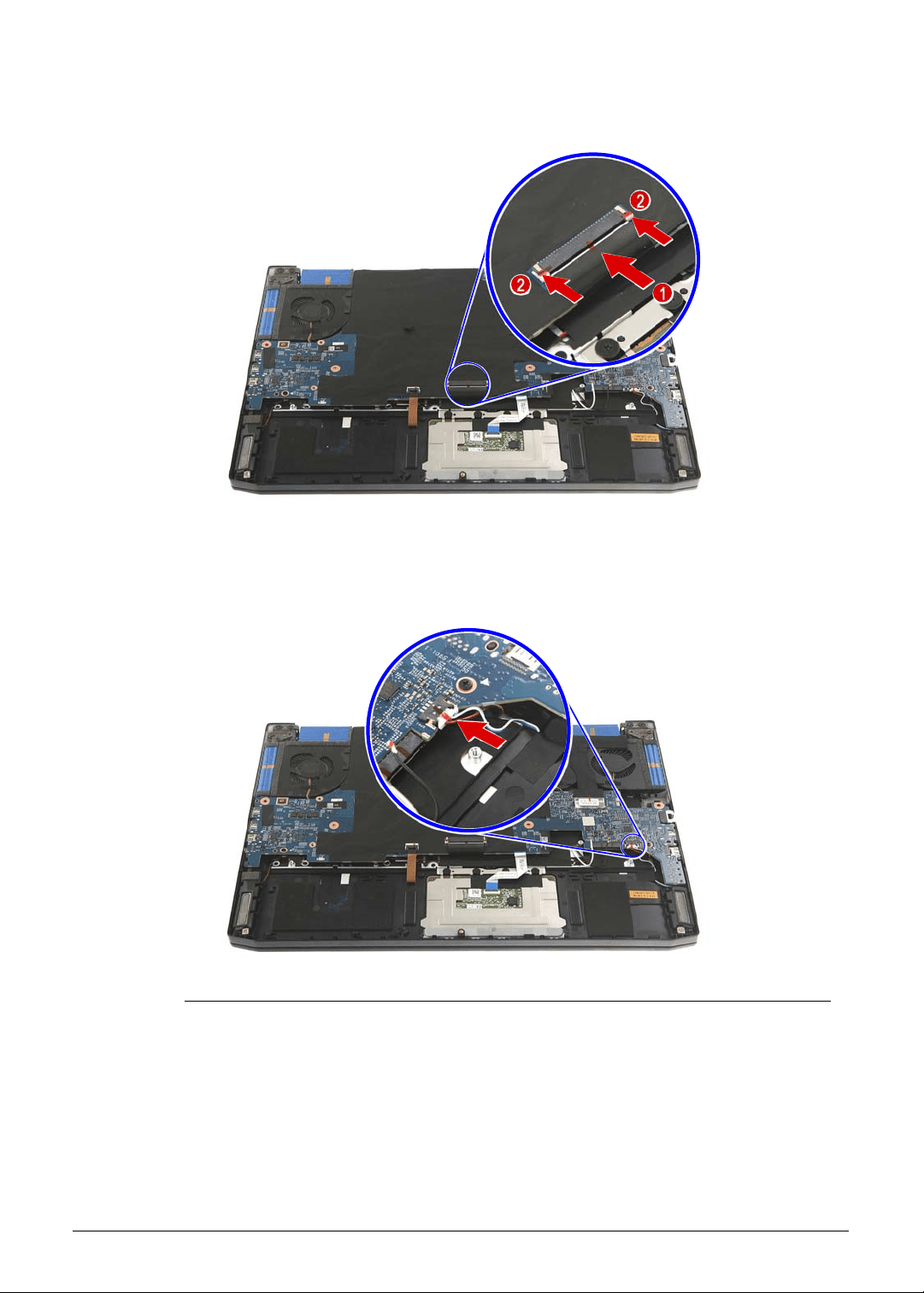
Machine Maintenance 3-75
7. Connect the keyboard cable to the mainboard.
Figure 3-111. Mainboard Connector - Keyboard Cable
8. Connect the speaker cable to the mainboard.
Figure 3-112. Mainboard Connector - Speaker Cable
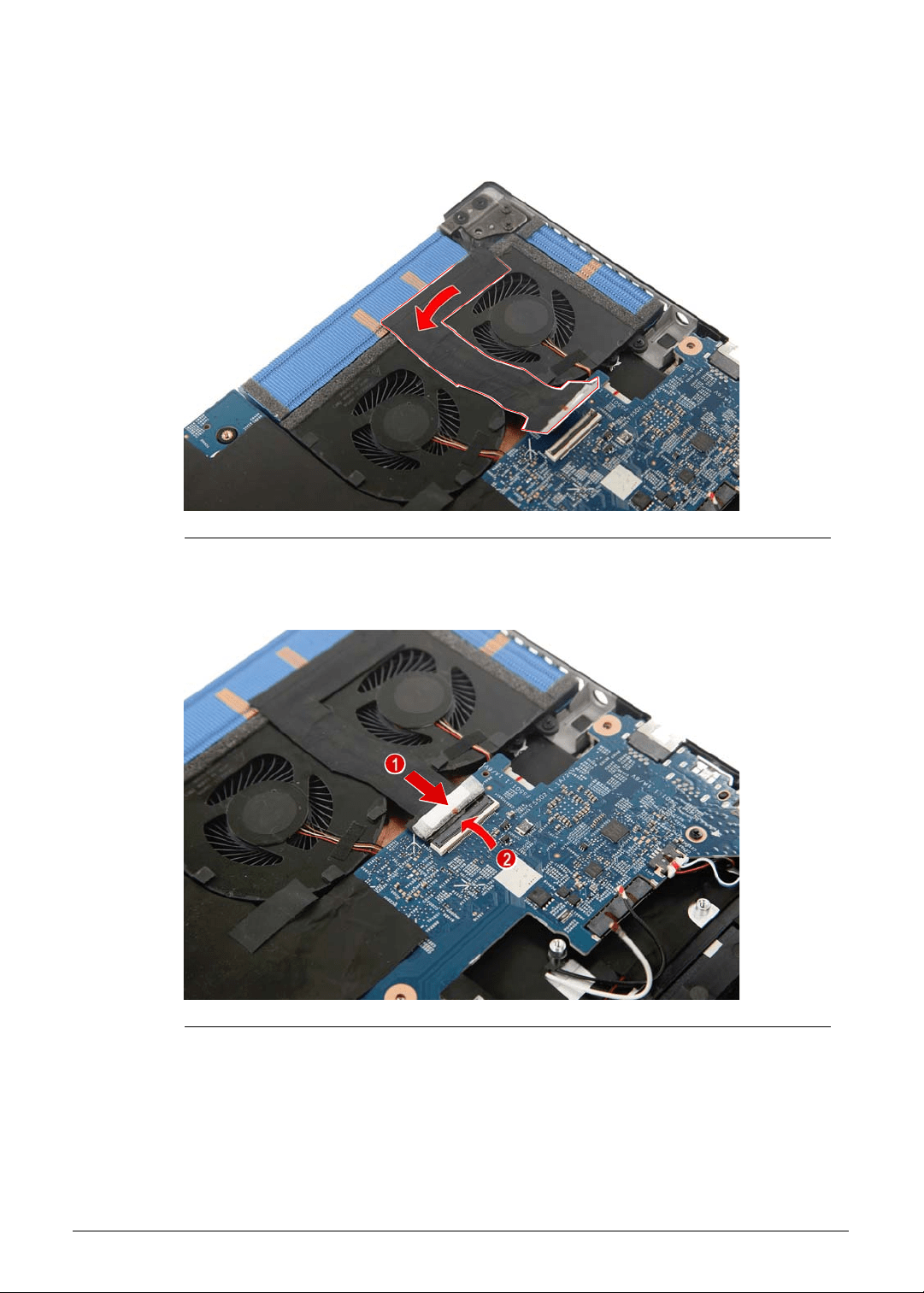
3-76 Machine Maintenance
9. Use self-adhesive tape to secure the eDP cable to the thermal fan.
Figure 3-113. eDP Cable Self-Adhesive Tape
10. Connect the eDP cable to the mainboard.
Figure 3-114. Mainboard Connector - eDP Cable
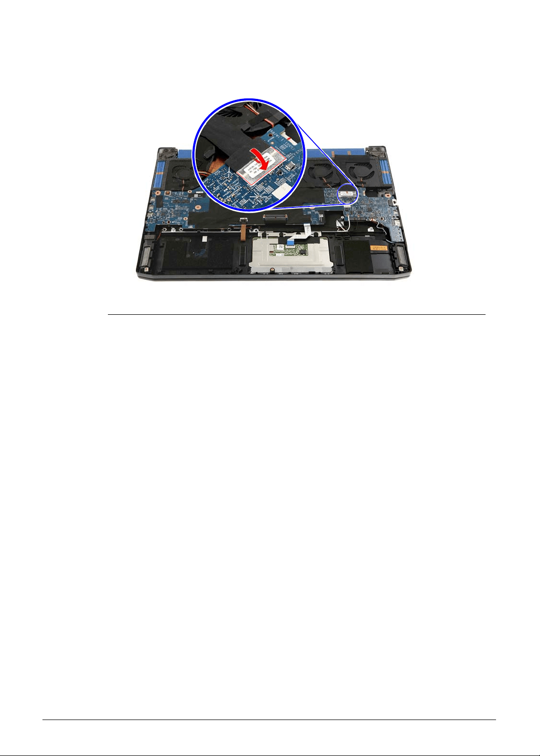
Machine Maintenance 3-77
11. Use transparent adhesive tape to secure the eDP cable to the mainboard.
Figure 3-115. eDP Cable Transparent Adhesive Tape
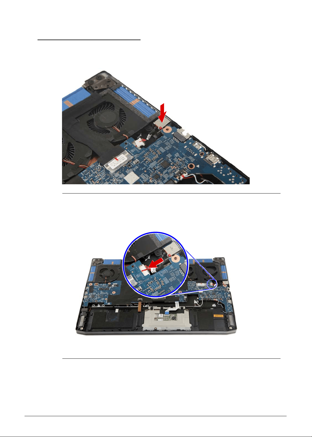
3-78 Machine Maintenance
Replacing the DC-In Cable 0
1. Insert the DC-In cable into the upper case.
Figure 3-116. DC-In Cable
2. Connect the DC-In cable to the mainboard.
Figure 3-117. Mainboard Connector - DC-In Cable
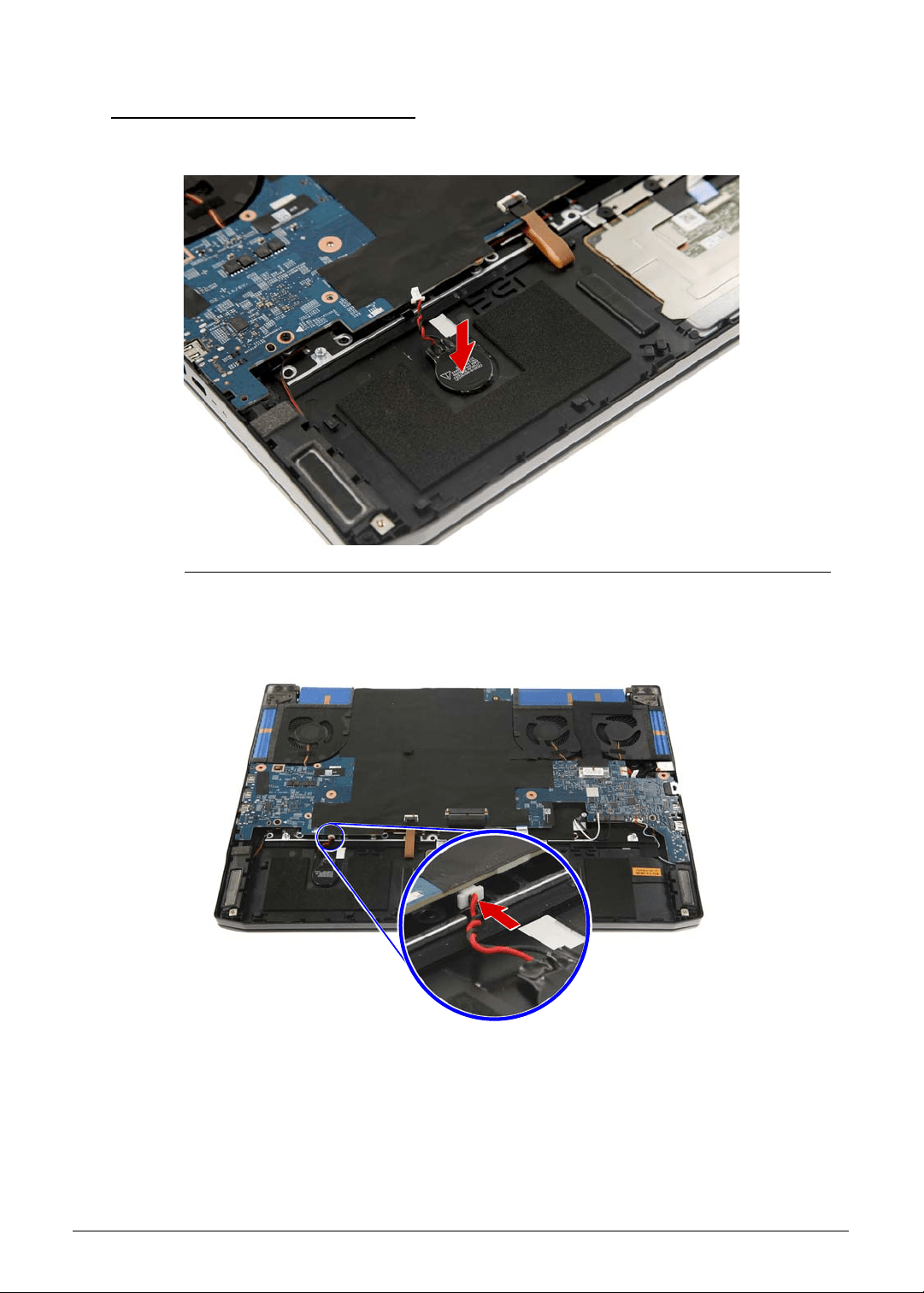
Machine Maintenance 3-79
Replacing the RTC Battery 0
1. Use self-adhesive tape to secure the RTC battery to the upper case.
Figure 3-118. RTC Battery
2. Connect the RTC battery cable to the mainboard.
Figure 3-119. Mainboard Connector - RTC Battery Cable
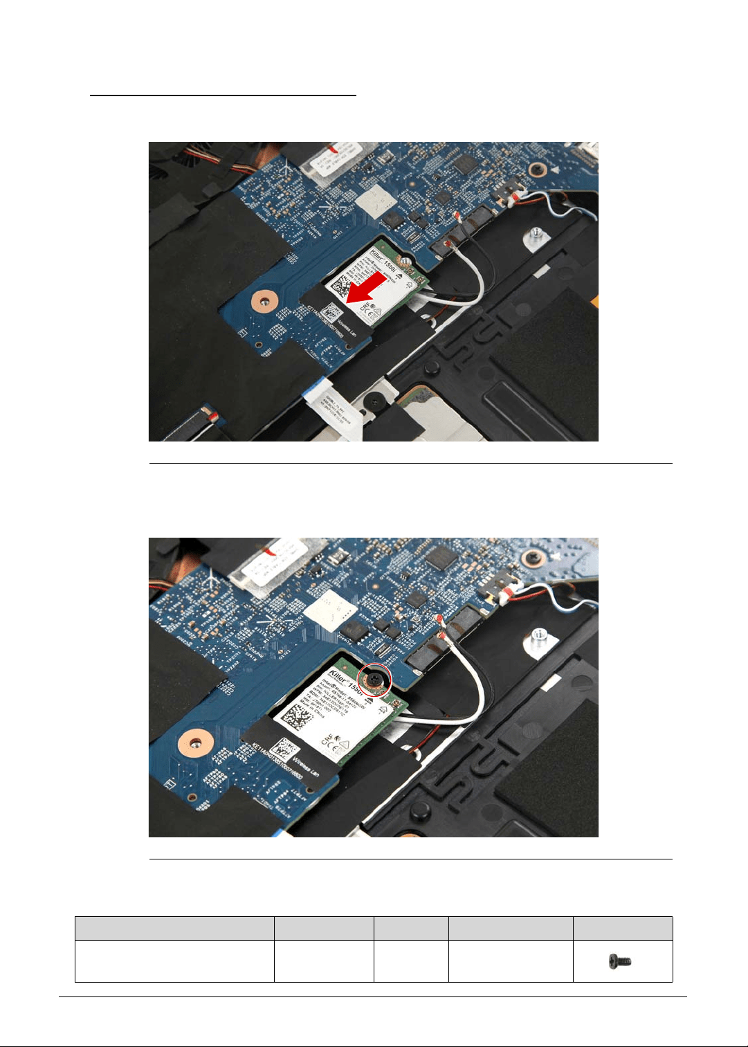
3-80 Machine Maintenance
Replacing the WLAN Module 0
1. Insert the WLAN module into the mainboard.
Figure 3-120. WLAN Module
2. Secure the WLAN module to the mainboard using one screw.
Figure 3-121. WLAN Module Screw
Table 3-121. Screw
Step Screw Quantity Torque Screw Type
WLAN Module Reassembly M2 × L4 6 1.6 ± 0.24 kgf cm
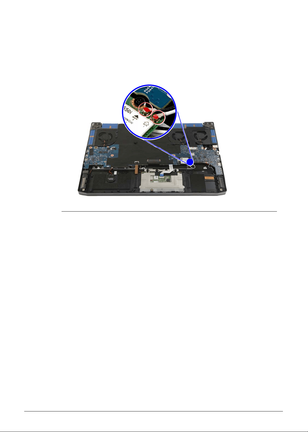
Machine Maintenance 3-81
3. Connect the antenna cables to the WLAN module. If you are installing a 1x1 WLAN board,
connect the black antenna cable to the WLAN module.
IMPORTANT:
+
Refer to your machine disassembly note to determine which cable color
corresponds to the main (black) and auxiliary (white) connectors.
Figure 3-122. WLAN Antenna Cables
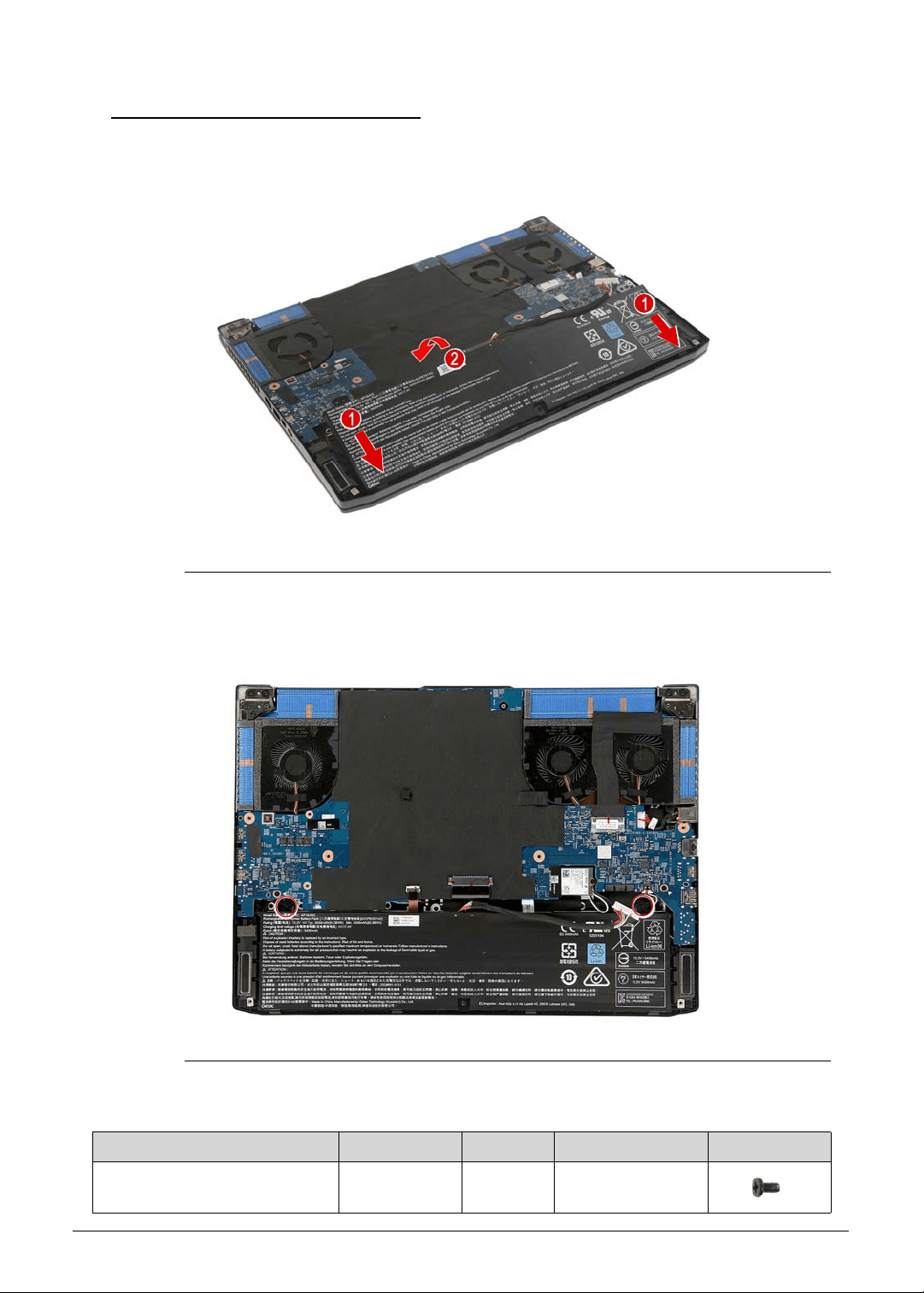
3-82 Machine Maintenance
Replacing the Battery Pack 0
1. Insert the battery pack into the upper case.
Figure 3-123. Battery Pack
2. Use two screws to secure the battery pack to the upper case.
Figure 3-124. Battery Pack Screws
Table 3-124. Screws
Step Screw Quantity Torque Screw Type
Battery Pack Reassembly M2 × L4 2 1.6 ± 0.24 kgf cm
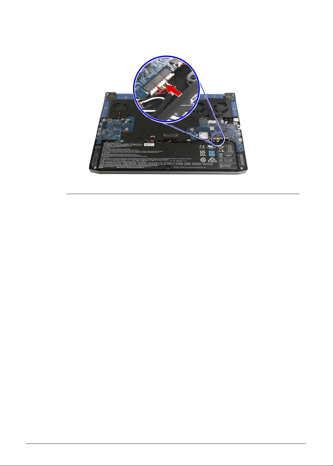
Machine Maintenance 3-83
3. Connect the battery cable to the mainboard.
Figure 3-125. Mainboard Connector - Battery Cable
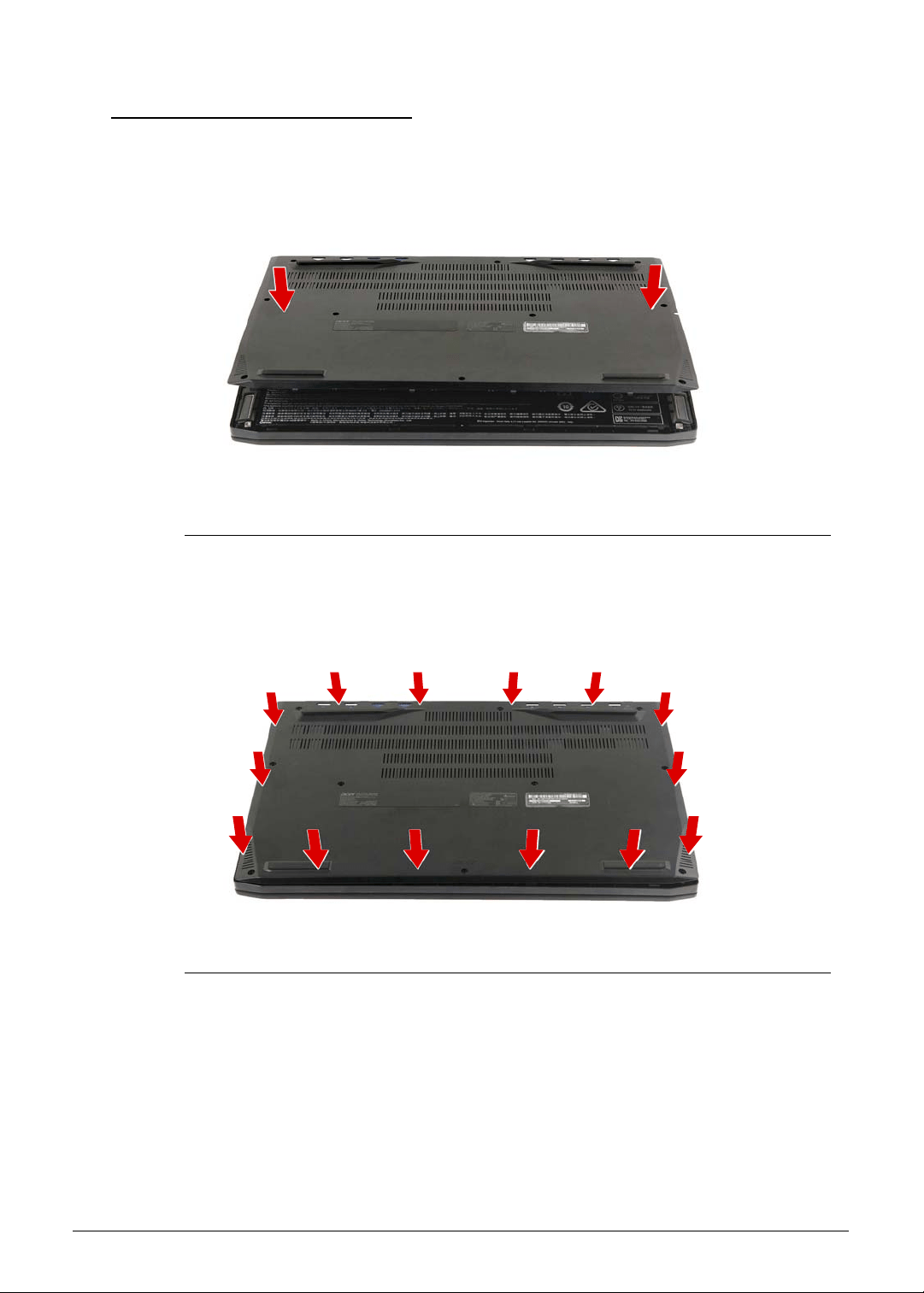
3-84 Machine Maintenance
Replacing the Lower Case 0
1. Place the lower case into the upper case.
Figure 3-126. Lower Case
2. Press the sides of the lower case into the upper case until it latches into place.
Figure 3-127. Lower Case Latches
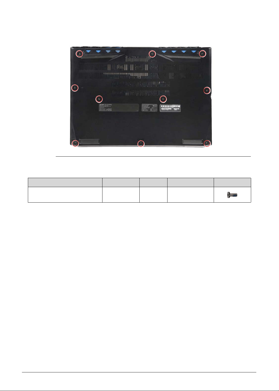
Machine Maintenance 3-85
3. Use ten screws to secure the lower case to the upper case.
Figure 3-128. Lower Case Screws
Table 3-128. Screws
Step Screw Quantity Torque Screw Type
Lower Case Reassembly M2.5 × L6 10 3.0 ± 0.45 kgf cm

3-86 Machine Maintenance

CHAPTER 4
Troubleshooting

4-2
General Information . . . . . . . . . . . . . . . . . . . . . . . . . . . . . . . . . . .4-3
Power On Issues . . . . . . . . . . . . . . . . . . . . . . . . . . . . . . . . . . . .4-4
No Display Issues . . . . . . . . . . . . . . . . . . . . . . . . . . . . . . . . . . .4-5
LCD Failure . . . . . . . . . . . . . . . . . . . . . . . . . . . . . . . . . . . . . . . .4-8
Keyboard Failure . . . . . . . . . . . . . . . . . . . . . . . . . . . . . . . . . . . .4-9
Keyboard Backlight Failure . . . . . . . . . . . . . . . . . . . . . . . . . . . .4-10
Touchpad Failure. . . . . . . . . . . . . . . . . . . . . . . . . . . . . . . . . . . .4-11
Internal Speaker Failure . . . . . . . . . . . . . . . . . . . . . . . . . . . . . .4-12
Microphone Failure . . . . . . . . . . . . . . . . . . . . . . . . . . . . . . . . . .4-14
USB Failure . . . . . . . . . . . . . . . . . . . . . . . . . . . . . . . . . . . . . . . .4-15
WLAN Failure . . . . . . . . . . . . . . . . . . . . . . . . . . . . . . . . . . . . . .4-16
Thermal Unit Failure . . . . . . . . . . . . . . . . . . . . . . . . . . . . . . . . .4-17
Other Functions Failure . . . . . . . . . . . . . . . . . . . . . . . . . . . . . . .4-18
Intermittent Problems. . . . . . . . . . . . . . . . . . . . . . . . . . . . . . . . . .4-19
Undetermined Problems. . . . . . . . . . . . . . . . . . . . . . . . . . . . . . . .4-19
POST Codes . . . . . . . . . . . . . . . . . . . . . . . . . . . . . . . . . . . . . . . . .4-20

Troubleshooting 4-3
Troubleshooting
This chapter contains information about troubleshooting common problems associated with
the Predator Triton 515-51 computer.
General Information 0
The following procedures are a guide for troubleshooting computer problems. The step by
step procedures are designed to be performed as described.
NOTE:
NOTE:
The diagnostic tests are intended for Acer products only. Non-Acer products, prototype
cards, or modified options can give false errors and invalid system responses.
1. Obtain as much detailed information as possible about the problem.
2. If possible, verify the symptoms by re-creating the failure through diagnostic tests or
repeating the operation that led to the problem.
3. Refer to Tab l e 4- 1 for a list of verified symptom category to determine the solution.
4. If the issue is still not resolved, refer to the Online Support Information on page 8-3
Table 4-1. Common Problems
Symptoms (Verified)
Power On Issues
No Display Issues
LCD Failure
Keyboard Failure
Touchpad Failure
Internal Speaker Failure
Microphone Failure
USB Failure
WLAN Failure
Thermal Unit Failure
Other Functions Failure
Intermittent Problems
Undetermined Problems
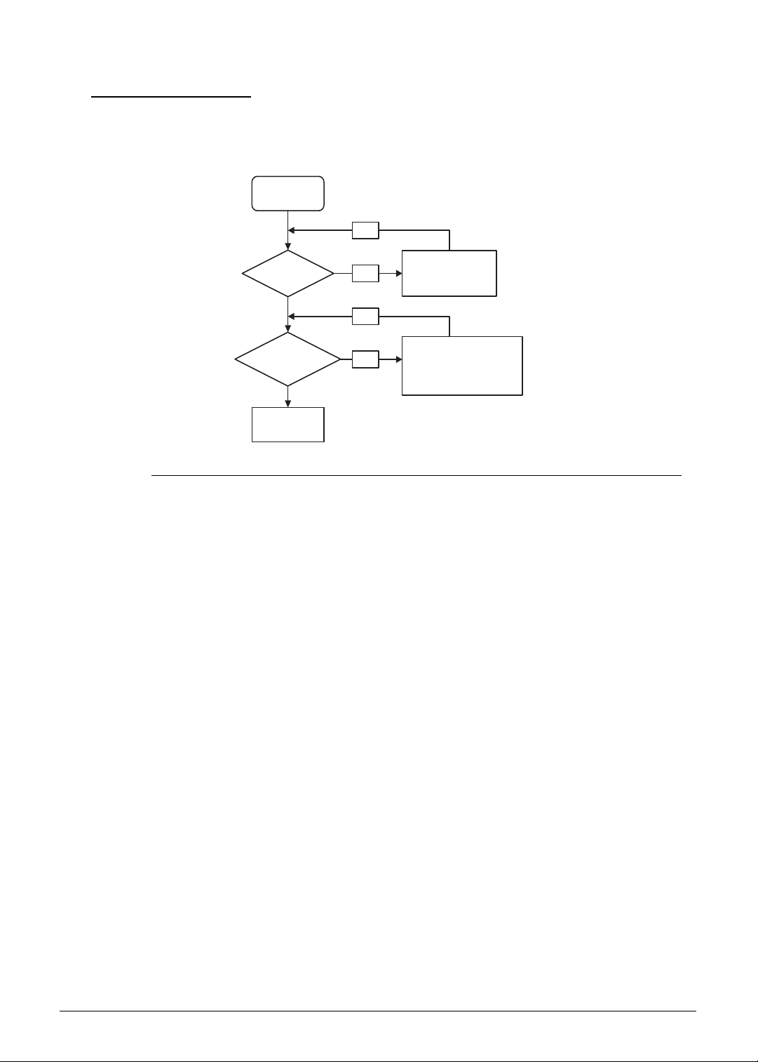
4-4 Troubleshooting
Power On Issues 0
If the system does not power on, perform the following, one at a time, to correct the problem.
Do not replace a non-defective FRU.
Figure 4-1. Power On Issue
Computer Shuts Down Intermittently 0
If the system powers off at intervals, perform the following.
1. Makes sure the power cable is properly connected to the computer and the electrical
outlet.
2. Remove all extension cables between the computer and the outlet.
3. Remove all surge protectors between the computer and the electrical outlet. Plug the
computer directly into a known serviceable electrical outlet.
4. Disconnect the power and open the casing to check the thermal module and fan airways
are free of obstructions. Refer to the to the “Thermal Unit Failure” section on page 4-17.
5. Remove all external and non-essential hardware connected to the computer that are not
necessary to boot the computer to the failure point.
6. Remove any recently installed software.
7. If the issue is still not resolved, refer to the Online Support Information on page 8-3.
Start
Check AC/Battery
Power on
Check
power/card reader
board/cable
connection
Replace Mainboard
Swap AC/Battery
OK
NG
Replace power/card reader board
Reconnect power/card reader
board cable
OK
NG
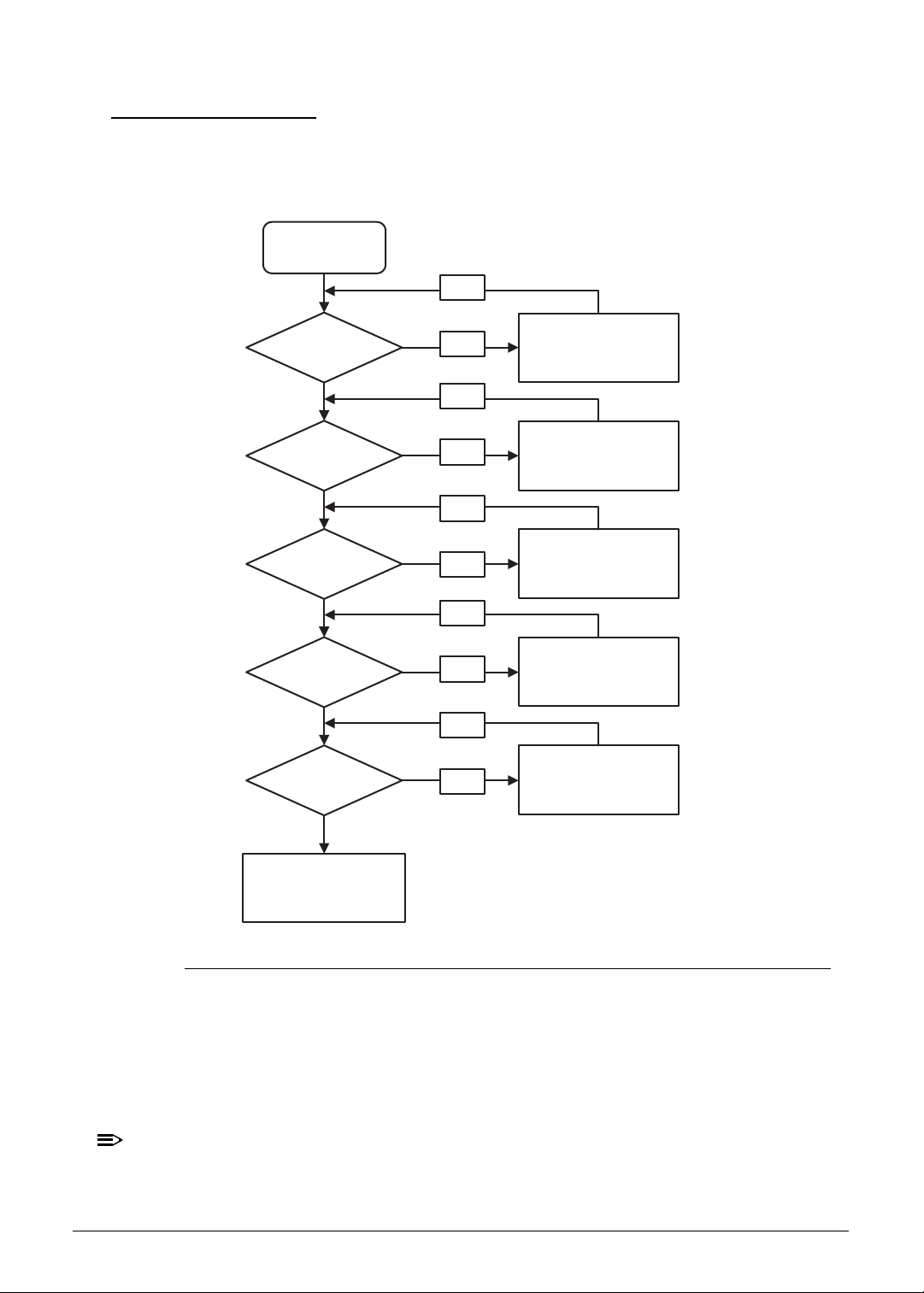
Troubleshooting 4-5
No Display Issues 0
If the Display does not work, perform the following, one at a time. Do not replace a
non-defective FRU:
Figure 4-2. No Display Issue
No POST or Video 0
If the POST or video does not appear, perform the following one at a time.
1. Make sure that internal display is selected. Switch between the internal and external
display by pressing Fn+F5.
NOTE:
NOTE:
This hotkey may not apply to all models. Refer to the computer’s user manual for the
applicable hotkey sequence.
Power on issues
Check
connection
Power On
Is ext. DDR RAM
module well
connected?
Is ext. DDR RAM
module OK?
Is the CPU heat sink
& fan module fastened
properly?
Replace
ext. DDR RAM
module
No
Reconnect fan cable/
Fasten CPU heat sink
screws
Replace
Mainboard
Is the LCD
module OK?
Replace LCD module/
Replace LCD cable
OK
No
OK
No
OK
No
OK
No
No
OK
No
Start

4-6 Troubleshooting
2. Make sure the computer has power by checking for one of the following:
Fans start up
Status LEDs illuminate
If there is no power, refer to the “Power On Issues” section on page 4-4.
3. Drain stored power by removing the power cable and the battery pack. Hold the power
button for 10 seconds.
4. Connect the power cable and reboot the computer.
5. Connect an external monitor to the computer and switch between the internal display and
the external display by pressing Fn+F5.
6. If the POST or video appears on the external display only, refer to the “LCD Failure”
section on page 4-8.
7. Disconnect power and all external devices including port replicators or docking stations.
8. Remove the lower case. Perform the “Removing the Lower Case” procedures described
on pages 3-9.
9. Remove the mainboard. Perform the “Removing the Mainboard” procedures described on
pages 3-17.
10. Remove the memory module. Perform the “Removing the Memory Modules” procedures
described on pages 3-32.
11. Start the computer. If the computer boots correctly, add the devices one by one until the
failure point is discovered.
12. Reinstall the memory module. Perform the “Replacing the Memory Module” procedures
described on pages 3-62.
13. If the issue is still not resolved, refer to the Online Support Information on page 8-3.
Abnormal Video 0
If the video appears abnormal, perform the following one at a time.
1. Boot the computer.
If permanent vertical/horizontal lines or dark spots appear in the same location, the LCD
panel is faulty and should be replaced. The same goes for when there is extensive pixel
damage (i.e. different colored spots in the same locations on the screen). Perform the
“Removing the Upper Case” and “Removing the LCD Panel” procedures described on
pages 3-39 and 3-44 respectively.
NOTE:
NOTE:
Make sure that the computer is not running on battery alone as this may reduce display
brightness.
2. Adjust the brightness to its highest level. Refer to the User Manual for instructions on
adjusting the settings. If the display is too dim at the highest brightness setting, the LCD is
faulty and should be replaced. Refer to Disassembly Process.
3. Check the display resolution is correctly configured:
Minimize or close all Windows.
If display size is only abnormal in an application, check the view settings and
control/mouse wheel zoom feature in the application.
If desktop display resolution is not normal, right-click on the desktop and select
Personalize Display Settings.
Click and drag the Resolution slider to the desired resolution.

Troubleshooting 4-7
Click Apply and check the display. Readjust if necessary.
4. Roll back the video driver to the previous version if updated.
5. Remove and reinstall the video driver.
6. Check the Device Manager to determine that:
The device is properly installed. There are no red Xs or yellow exclamation marks
There are no device conflicts
No hardware is listed under Other Devices
7. If the issue is still not resolved, refer to the Online Support Information on page 8-3.
8. Run the Windows Memory Diagnostic from the operating system DVD and follow the
on-screen prompts.
9. If the issue is still not resolved, refer to the Online Support Information on page 8-3.
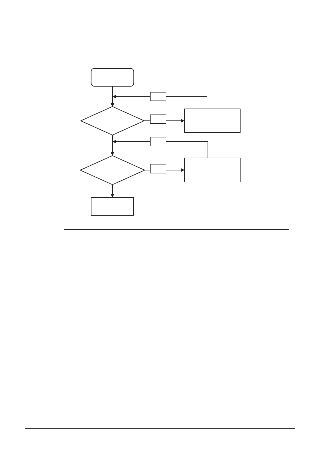
4-8 Troubleshooting
LCD Failure 0
If the LCD fails, perform the following, one at a time. Do not replace a non-defective FRU:
Figure 4-3. LCD Failure
Start
Check LCD
module
Check LCD
cable and LCD
connector
Replace Mainboard
Replace LCD
module
OK
NG
Reconnect
LCD cable
OK
NG
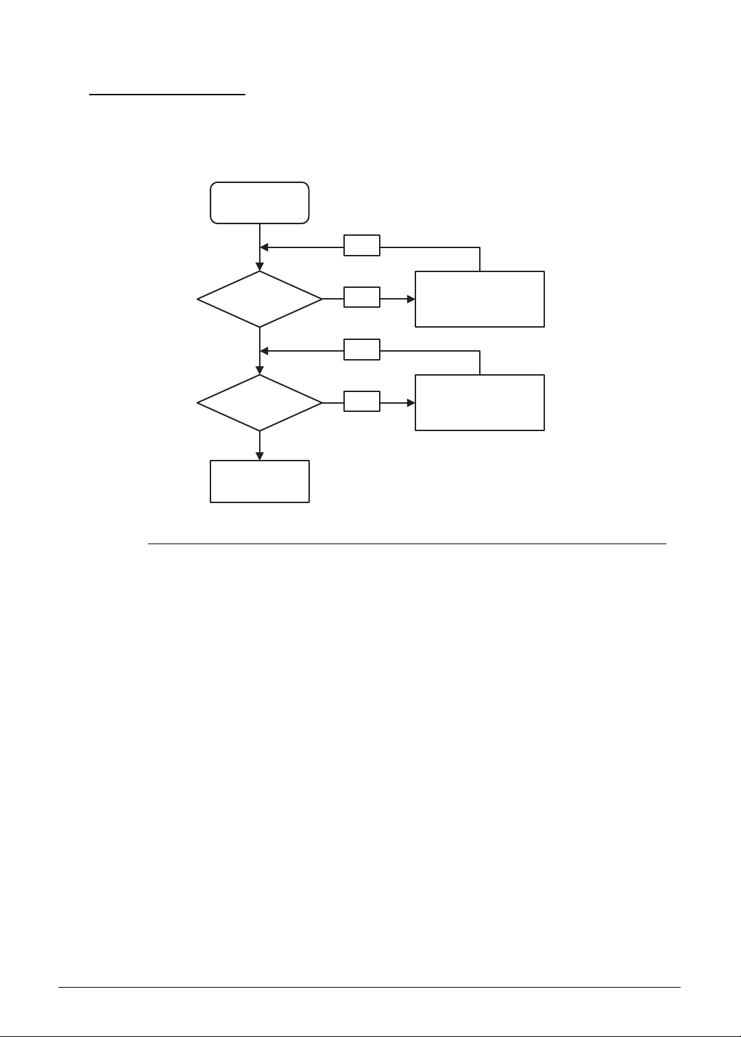
Troubleshooting 4-9
Keyboard Failure 0
If the Keyboard fails, perform the following, one at a time. Do not replace a non-defective
FRU:
Figure 4-4. Keyboard Failure
Start
Check keyboard
backlight cable
connection
Check keyboard
Replace Mainboard
Reconnect
Keyboard backlight
cable
Replace Palm rest/
Upper case assembly
(with keyboard)
OK
NG
OK
NG
Start
Check keyboard
cable connection
Check keyboard
Replace Mainboard
Reconnect
Keyboard cable
Replace Palm rest/
Upper case assembly
(with keyboard)
OK
NG
OK
NG
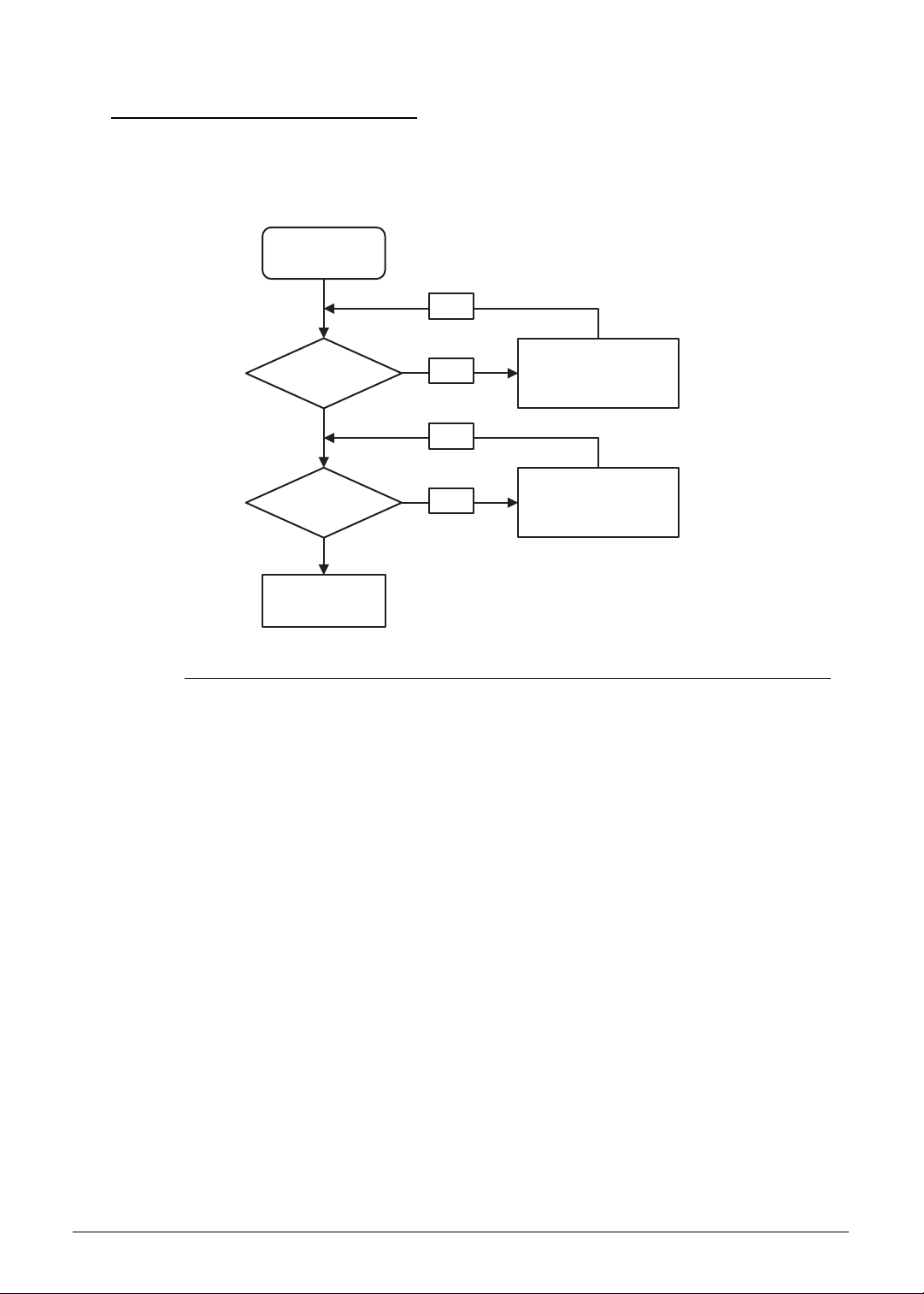
4-10 Troubleshooting
Keyboard Backlight Failure 0
If the Keyboard backlight fails, perform the following, one at a time. Do not replace a
non-defective FRU:
Figure 4-5. Keyboard Failure
Start
Check keyboard
backlight cable
connection
Check keyboard
Replace Mainboard
Reconnect
Keyboard backlight
cable
Replace Palm rest/
Upper case assembly
(with keyboard)
OK
NG
OK
NG
Start
Check keyboard
backlight cable
connection
Check keyboard
Replace Mainboard
Reconnect
Keyboard backlight
cable
Replace Palm rest/
Upper case assembly
(with keyboard)
OK
NG
OK
NG
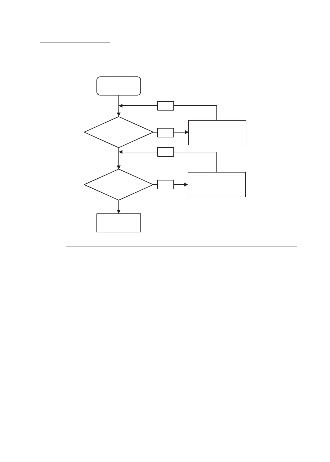
Troubleshooting 4-11
Touchpad Failure 0
If the Touchpad fails, perform the following, one at a time. Do not replace a non-defective
FRU:
Figure 4-6. Touchpad Failure
Start
Check Touchpad
cable connection
Check
Touchpad board
Replace Mainboard
Reconnect the
Touchpad cable to
Mainboard
OK
NG
Replace the
Touchpad module/
Touchpad cable
OK
NG

4-12 Troubleshooting
Internal Speaker Failure 0
If internal Speakers fail, perform the following, one at a time. Do not replace a non-defective
FRU:
Figure 4-7. Internal Speaker Failure
Sound Problems 0
Perform the following, one at a time.
1. Boot the computer.
2. Drag the mouse pointer to the top or bottom right corner of the screen until the Charms bar
appear along the right edge of the screen.
3. Click Search.
4. Enter Device Manager in the search box and click Device Manager.
5. Check the Device Manager to determine that:
The device is properly installed
There are no red Xs or yellow exclamation marks
There are no device conflicts
No hardware is listed under Other Devices
6. If updated recently, roll back the audio driver to the previous version.
7. Remove and reinstall the audio driver.
Start
Check Speaker cable
connection
Check Speaker
module
Replace Mainboard
Reconnect the
Speaker cable
OK
NG
Replace Speaker module
OK
NG

Troubleshooting 4-13
8. Make sure that all volume controls are set mid range:
Click the volume icon on the task bar
Drag the slider to 50. Confirm that the volume is not muted.
Click Mixer to verify that other audio applications are set to 50 and not muted.
9. Enter Control Panel in the search box and click Control Panel.
10. Click Hardware and Sound Sound. Confirm that Speakers are selected as the
default audio device (green check mark).
NOTE:
NOTE:
If Speakers do not show, right-click on the Playback tab and select Show Disabled
Devices (clear by default).
11. Select Speakers and click Configure to start Speaker Setup. Follow the on-screen
prompts to configure the speakers.
12. Remove any recently installed hardware or software.
13. Restore system and file settings from a known good date using System Restore.
14. If the issue is remains, repeat step 12, selecting an earlier time and date.
15. Reinstall the Operating System.
16. If the issue is still not resolved, refer to the Online Support Information on page 8-3.

4-14 Troubleshooting
Microphone Failure 0
Perform the following:
1. Enter Control Panel in the search box and click Control Panel.
2. Click Hardware and Sound Sound and select the Recording tab.
3. Right click on the Recording tab and select Show Disabled Devices (clear by
default). The microphone appears on the Recording tab.
4. Right click on the microphone and select Enable.
5. Select the microphone then click Properties. Select the Levels tab.
6. Increase the volume to the maximum setting and click OK.
7. Test the microphone hardware:
Select the microphone and click Configure.
Select Set up microphone.
Select the microphone type from the list and click Next.
Follow the on-screen prompts to complete the test.
8. If the issue is still not resolved, refer to the Online Support Information on page 8-3.
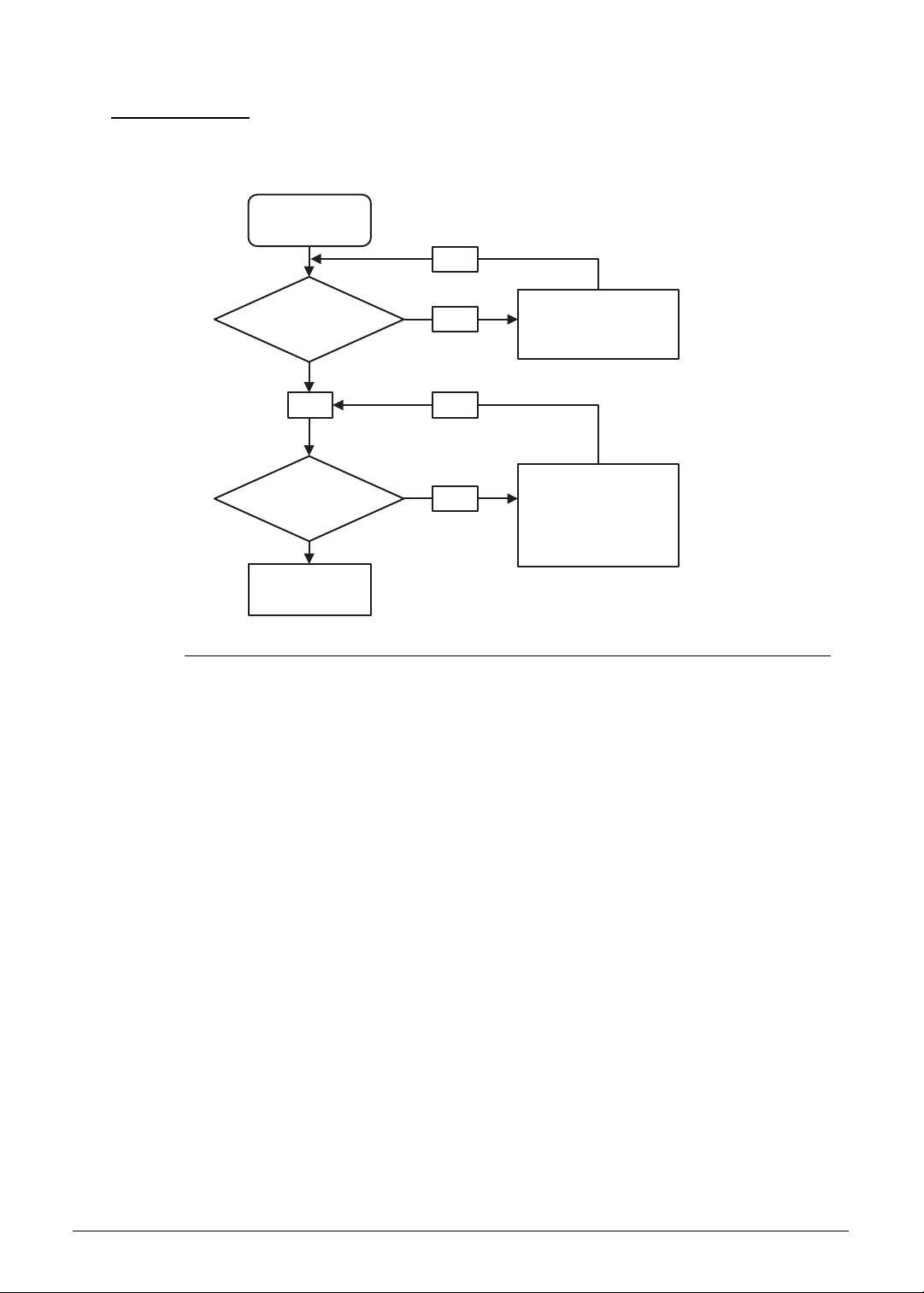
Troubleshooting 4-15
USB Failure 0
If the USB fails, perform the following, one at a time. Do not replace a non-defective FRU:
Figure 4-8. USB Failure
Start
Check power/card
reader board
cable connection
Replace Mainboard
Reconnect power/card
reader board cable
OK
OK
NG
Replace power/card reader
board cable
Replace power/card reader
board
OK
NG
Check power/card
reader board
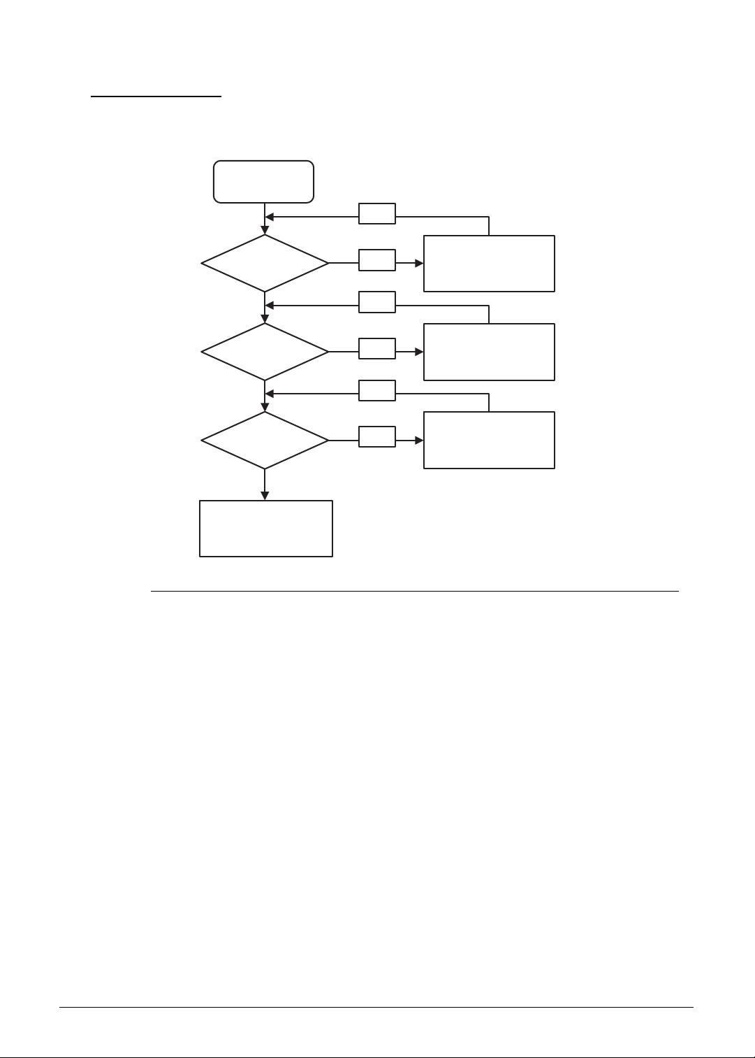
4-16 Troubleshooting
WLAN Failure 0
If the WLAN fails, perform the following, one at a time. Do not replace a non-defective FRU:
Figure 4-9. WLAN Failure
Reconnect the
WLAN/WiMax antenna
OK
Replace the
antenna cable
Check WLAN/Wimax
antenna connection
Check antenna
cable
Check WLAN/
WiMax card
Replace Mainboard
Replace the
WLAN/WiMax card
OK
OK
NG
OK
NG
OK
NG
Start
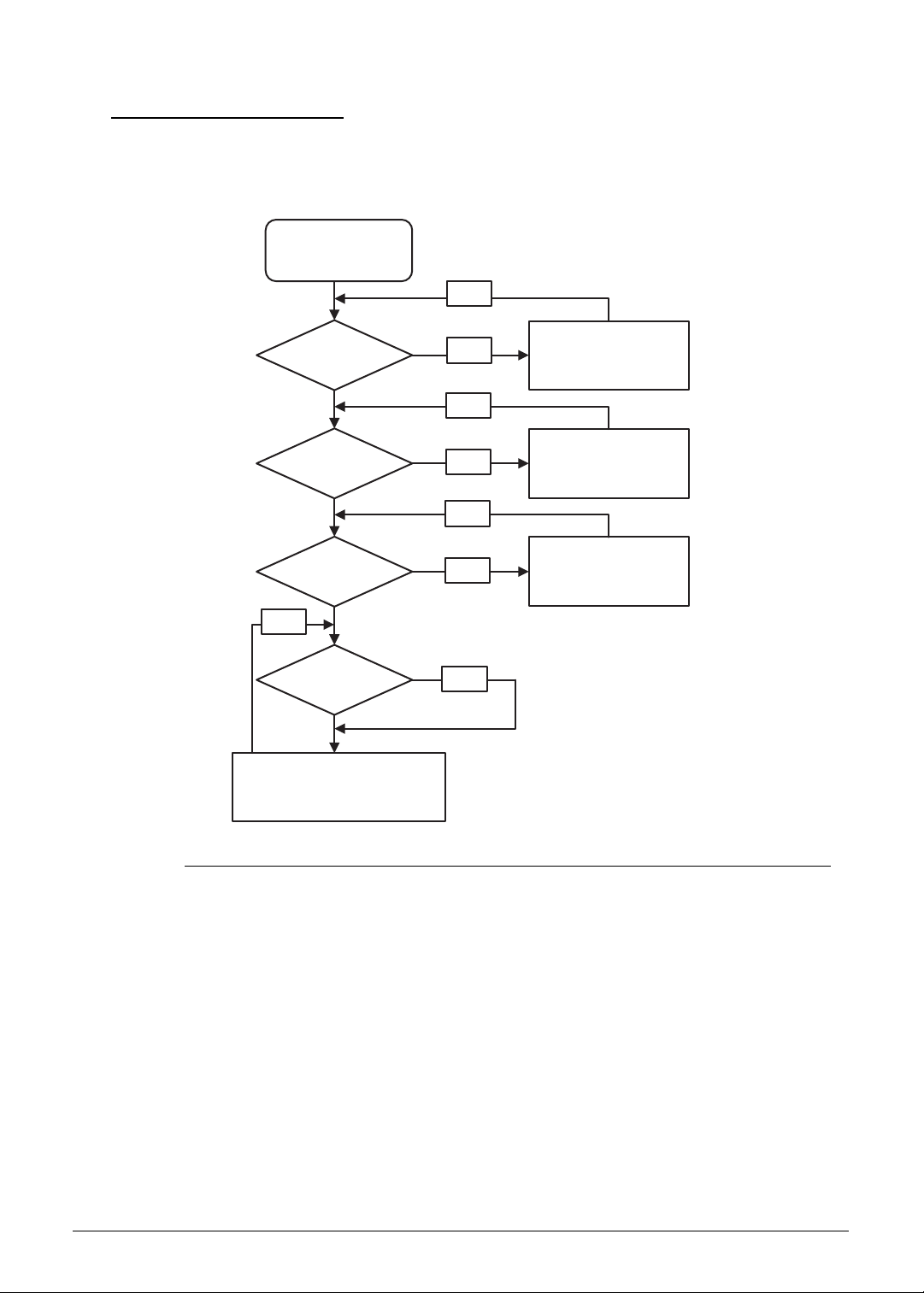
Troubleshooting 4-17
Thermal Unit Failure 0
If the Thermal Unit fails, perform the following, one at a time. Do not replace a non-defective
FRU:
Figure 4-10. Thermal Unit Failure
Reconnect Fan cable
Replace the
Heat sink module
Check Fan cable
connection
Check Fan
Check Heat sink
module is well seated
Is CPU OK?
Replace M/B
Reseat and fasten
heat sink module screws
Start
OK
No
OK
No
OK
No
No
OK

4-18 Troubleshooting
Other Functions Failure 0
1. Check if drives are functioning correctly.
2. Check if external modules are functioning correctly.
3. Change mainboard to check if current one is defective.

Troubleshooting 4-19
Intermittent Problems 0
Intermittent system hang problems can be caused by a variety of reasons that have nothing to
do with a hardware defect, such as: cosmic radiation, electrostatic discharge, or software
errors. FRU replacement should be considered only when a recurring problem exists.
When analyzing an intermittent problem, perform the following:
1. Run the advanced diagnostic test for the system board in loop mode at least 10 times.
2. If no error is detected, do not replace any FRU.
3. If an error is detected, replace the FRU. Rerun the test to verify that there are no more
errors.
Undetermined Problems 0
The diagnostic problems does not identify which adapter or device failed, which installed
devices are incorrect, whether a short circuit is suspected, or whether the system is
inoperative.
Perform the following procedures to isolate the failing FRU (do not replace non-defective
FRU).
NOTE:
NOTE:
Verify that all attached devices are supported by the computer.
NOTE:
NOTE:
Verify that the power supply being used at the time of the failure is operating correctly.
1. Remove power from the computer.
2. Visually check the components for damage. If any problems are found, replace the FRU.
3. Remove or disconnect all of the following devices:
Non-Acer devices
Printer, mouse, and other external devices
Battery pack
Hard disk drive
DIMM
CD-ROM/Diskette drive Module
PC Cards
4. Apply power to the computer.
5. Determine if the problem has changed.
6. If the problem does not recur, connect the removed devices one at a time until failing FRU
is found.
7. If the problem remains, replace the following FRUs one at a time. Do not replace a
non-defective FRU:
Mainboard
LCD assembly
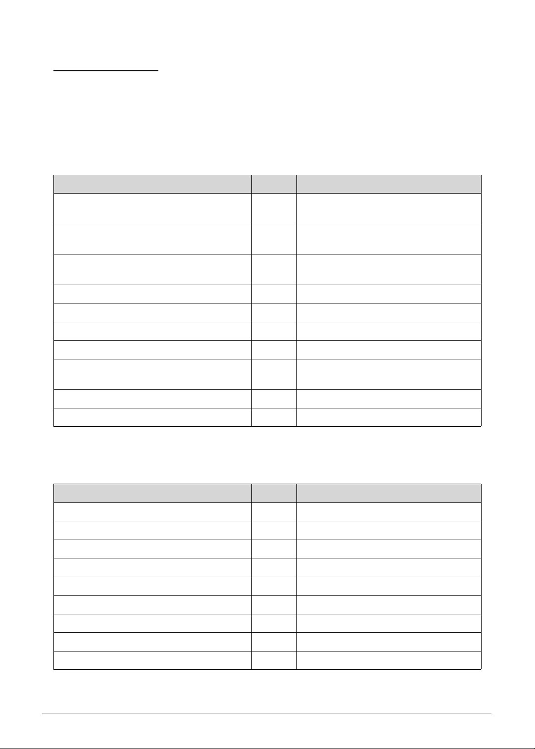
4-20 Troubleshooting
POST Codes 0
The following are the InsydeH2O™ Functionality POST code tables. The components of the
POST code table includes: SEC functionality, PEI functionality, DXE functionality, BDS
functionality, POST BDS functionality, SMM functionality, S3 functionality, and ASL
functionality.
Table 4-2. SEC Functionality
Definition Code Description
#define SEC_SYSTEM_POWER_ON 0x01 CPU power on and switch to Protected
mode
#define
SEC_BEFORE_MICROCODE_PATCH
0x02 Patching CPU microcode
#define
SEC_AFTER_MICROCODE_PATCH
0x03 Setup Cache as RAM
#define SEC_ACCESS_CSR 0x04 PCIE MMIO Base Address initial
#define SEC_GENERIC_MSRINIT 0x05 CPU Generic MSR initial
#define SEC_CPU_SPEEDCFG 0x06 Setup CPU speed
#define SEC_SETUP_CAR_OK 0x07 Cache as RAM test
#define SEC_FORCE_MAX_RATIO 0x08 Tune CPU frequency ratio to maximum
level
#define SEC_GO_TO_SECSTARTUP 0x09 Setup BIOS ROM cache
#define SEC_GO_TO_PEICORE 0x0A Enter Boot Firmware Volume
Table 4-3. PEI Functionality
Definition Code Description
#define PEI_SIO_INIT 0x70 Super I/O initial
#define PEI_CPU_REG_INIT 0x71 CPU Early Initial
#define PEI_CPU_AP_INIT 0x72 Multi-processor Early initial
#define PEI_CPU_HT_RESET 0x73 HyperTransport initial
#define PEI_PCIE_MMIO_INIT 0x74 PCIE MMIO BAR Initial
#define PEI_NB_REG_INIT 0x75 North Bridge Early Initial
#define PEI_SB_REG_INIT 0x76 South Bridge Early Initial
#define PEI_PCIE_TRAINING 0x77 PCIE Training
#define PEI_TPM_INIT 0x78 TPM Initial

Troubleshooting 4-21
#define PEI_SMBUS_INIT 0x79 SMBUS Early Initial
#define PEI_PROGRAM_CLOCK_GEN 0x7A Clock Generator Initial
#define PEI_IGD_EARLY_INITIAL 0x7B Internal Graphic device early initial,
PEI_IGDOpRegion
#define PEI_HECI_INIT 0x7C HECI Initial
#define PEI_WATCHDOG_INIT 0x7D Watchdog timer initial
#define PEI_MEMORY_INIT 0x7E Memory Initial for Normal boot
#define
PEI_MEMORY_INIT_FOR_CRISIS
0x7F Memory Initial for Crisis Recovery
#define PEI_MEMORY_INSTALL 0x80 Simple Memory test
#define PEI_TXTPEI 0x81 TXT function early initial
#define PEI_SWITCH_STACK 0x82 Start to use Memory
#define PEI_MEMORY_CALLBACK 0x83 Set cache for physical memory
#define PEI_ENTER_RECOVERY_MODE 0x84 Recovery device initial
#define
PEI_RECOVERY_MEDIA_FOUND
0x85 Found Recovery image
#define
PEI_RECOVERY_MEDIA_NOT_FOUND
0x86 Recovery image not found
#define
PEI_RECOVERY_LOAD_FILE_DONE
0x87 Load Recovery Image complete
#define PEI_RECOVERY_START_FLASH 0x88 Start Flash BIOS with Recovery image
#define PEI_ENTER_DXEIPL 0x89 Loading BIOS image to RAM
#define PEI_FINDING_DXE_CORE 0x8A Loading DXE core
#define PEI_GO_TO_DXE_CORE 0x8B Enter DXE core
#define PEI_IFFS_TRANSITION_START 0x8C iFFS Transition Start
#define PEI_IFFS_TRANSITION_END 0x8D iFFS Transition End
Table 4-3. PEI Functionality (Continued)
Definition Code Description

4-22 Troubleshooting
Table 4-4. DXE Functionality
Definition Code Description
#define DXE_TCGDXE 0x40 TPM initial in DXE
#define DXE_SB_SPI_INIT 0x41 South bridge SPI initial
#define DXE_CF9_RESET 0x42 Setup Reset service, DXE_CF9Reset
#define DXE_SB_SERIAL_GPIO_INIT 0x43 South bridge Serial GPIO initial,
DXE_SB_SerialGPIO_INIT
#define DXE_SMMACCESS 0x44 Setup SMM ACCESS service
#define DXE_NB_INIT 0x45 North bridge Middle initial
#define DXE_SIO_INIT 0x46 Super I/O DXE initial
#define DXE_LEGACY_REGION 0x47 Setup Legacy Region service,
DXE_LegacyRegion
#define DXE_SB_INIT 0x48 South Bridge Middle Initial
#define DXE_IDENTIFY_FLASH_DEVICE 0x49 Identify Flash device
#define DXE_FTW_INIT 0x4A Fault Tolerant Write verification
#define DXE_VARIABLE_INIT 0x4B Variable Service Initial
#define DXE_VARIABLE_INIT_FAIL 0x4C Fail to initial Variable Service
#define DXE_MTC_INIT 0x4D MTC Initial
#define DXE_CPU_INIT 0x4E CPU Middle Initial
#define DXE_MP_CPU_INIT 0x4F Multi-processor Middle Initial
#define DXE_SMBUS_INIT 0x50 SMBUS Driver Initial
#define DXE_SMART_TIMER_INIT 0x51 8259 Initial
#define DXE_PCRTC_INIT 0x52 RTC Initial
#define DXE_SATA_INIT 0x53 SATA Controller early initial
#define DXE_SMM_CONTROLER_INIT 0x54 Setup SMM Control service,
DXE_SMMControler_INIT
#define DXE_LEGACY_INTERRUPT 0x55 Setup Legacy Interruput service,
DXE_LegacyInterrupt
#define DXE_RELOCATE_SMBASE 0x56 Relocate SMM BASE
#define DXE_FIRST_SMI 0x57 SMI test
#define DXE_VTD_INIT 0x58 VTD Initial
#define DXE_BEFORE_CSM16_INIT 0x59 Legacy BIOS initial
#define DXE_AFTER_CSM16_INIT 0x5A Legacy interrupt function initial
#define DXE_LOAD_ACPI_TABLE 0x5B ACPI Table Initial
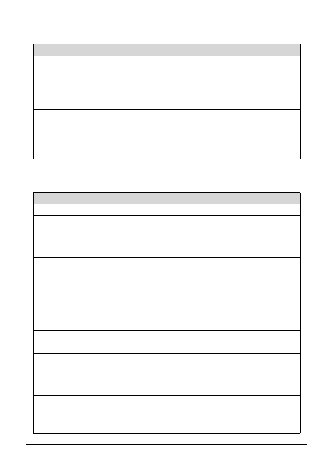
Troubleshooting 4-23
#define DXE_SB_DISPATCH 0x5C Setup SB SMM Dispatcher service,
DXE_SB_Dispatch
#define DXE_SB_IOTRAP_INIT 0x5D Setup SB IOTRAP Service
#define DXE_SUBCLASS_DRIVER 0x5E Build AMT Table
#define DXE_PPM_INIT 0x5F PPM Initial
#define DXE_HECIDRV_INIT 0x60 HECIDRV Initial
#define DXE_VARIABLE_RECLAIM 0x61 Variable store garbage collection and
reclaim operation
#define
DXE_FLASH_PART_NONSUPPORT
0x62 Do not support flash part (which is
defined in SpiDevice.c)
Table 4-5. BDS Functionality
Definition Code Description
#define BDS_ENTER_BDS 0x10 Enter BDS entry
#define BDS_INSTALL_HOTKEY 0x11 Install Hotkey service
#define BDS_ASF_INIT 0x12 ASF Initial
#define BDS_PCI_ENUMERATION_
START
0x13 PCI enumeration
#define BDS_BEFORE_PCIIO_INSTALL 0x14 PCI resource assign complete
#define BDS_PCI_ENUMERATION_END 0x15 PCI enumeration complete
#define BDS_CONNECT_CONSOLE_IN 0x16 Keyboard Controller, Keyboard and
Mouse initial
#define
BDS_CONNECT_CONSOLE_OUT
0x17 Video device initial
#define BDS_CONNECT_STD_ERR 0x18 Error report device initial
#define BDS_CONNECT_USB_HC 0x19 USB host controller initial
#define BDS_CONNECT_USB_BUS 0x1A USB BUS driver initial
#define BDS_CONNECT_USB_DEVICE 0x1B USB device driver initial
#define BDS_NO_CONSOLE_ACTION 0x1C Console device initial fail
#define BDS_DISPLAY_LOGO_SYSTEM
_INFO
0x1D Display logo or system information
#define BDS_START_IDE_
CONTROLLER
0x1E IDE controller initial
#define BDS_START_SATA_
CONTROLLER
0x1F SATA controller initial
Table 4-4. DXE Functionality
Definition Code Description

4-24 Troubleshooting
#define BDS_START_ISA_ACPI_
CONTROLLER
0x20 SIO controller initial
#define BDS_START_ISA_BUS 0x21 ISA BUS driver initial
#define BDS_START_ISA_FDD 0x22 Floppy device initial
#define BDS_START_ISA_SEIRAL 0x23 Serial device initial
#define BDS_START_IDE_BUS 0x24 IDE device initial
#define BDS_START_AHCI_BUS 0x25 AHCI device initial
#define BDS_CONNECT_LEGACY_ROM 0x26 Dispatch option ROMs
#define BDS_ENUMERATE_ALL_BOOT_
OPTION
0x27 Get boot device information
#define BDS_END_OF_BOOT_
SELECTION
0x28 End of boot selection
#define BDS_ENTER_SETUP 0x29 Enter Setup Menu
#define BDS_ENTER_BOOT_MANAGER 0x2A Enter Boot manager
#define BDS_BOOT_DEVICE_SELECT 0x2B Try to boot system to OS
#define BDS_EFI64_SHADOW_ALL_
LEGACY_ROM
0x2C Shadow Misc Option ROM
#define BDS_ACPI_S3SAVE 0x2D Save S3 resume required data in RAM
#define BDS_READY_TO_BOOT_EVENT 0x2E Last Chipset initial before boot to OS
#define BDS_GO_LEGACY_BOOT 0x2F Start to boot Legacy OS
#define BDS_GO_UEFI_BOOT 0x30 Start to boot UEFI OS
#define
BDS_LEGACY16_PREPARE_TO_BOOT
0x31 Prepare to Boot to Legacy OS
#define BDS_EXIT_BOOT_SERVICES 0x32 Send END of POST Message to ME via
HECI
#define BDS_LEGACY_BOOT_EVENT 0x33 Last Chipset initial before boot to
Legacy OS
#define
BDS_ENTER_LEGACY_16_BOOT
0x34 Ready to Boot Legacy OS
#define
BDS_RECOVERY_START_FLASH
0x35 Fast recovery start flash
#define BDS_START_SDHC_BUS 0x36 SDHC device initial
#define BDS_CONNECT_ATA_LEGACY 0x37 Ata Legacy device initial
#define BDS_CONNECT_SD_LEGACY 0x38 SD Legacy device initial
Table 4-5. BDS Functionality (Continued)
Definition Code Description
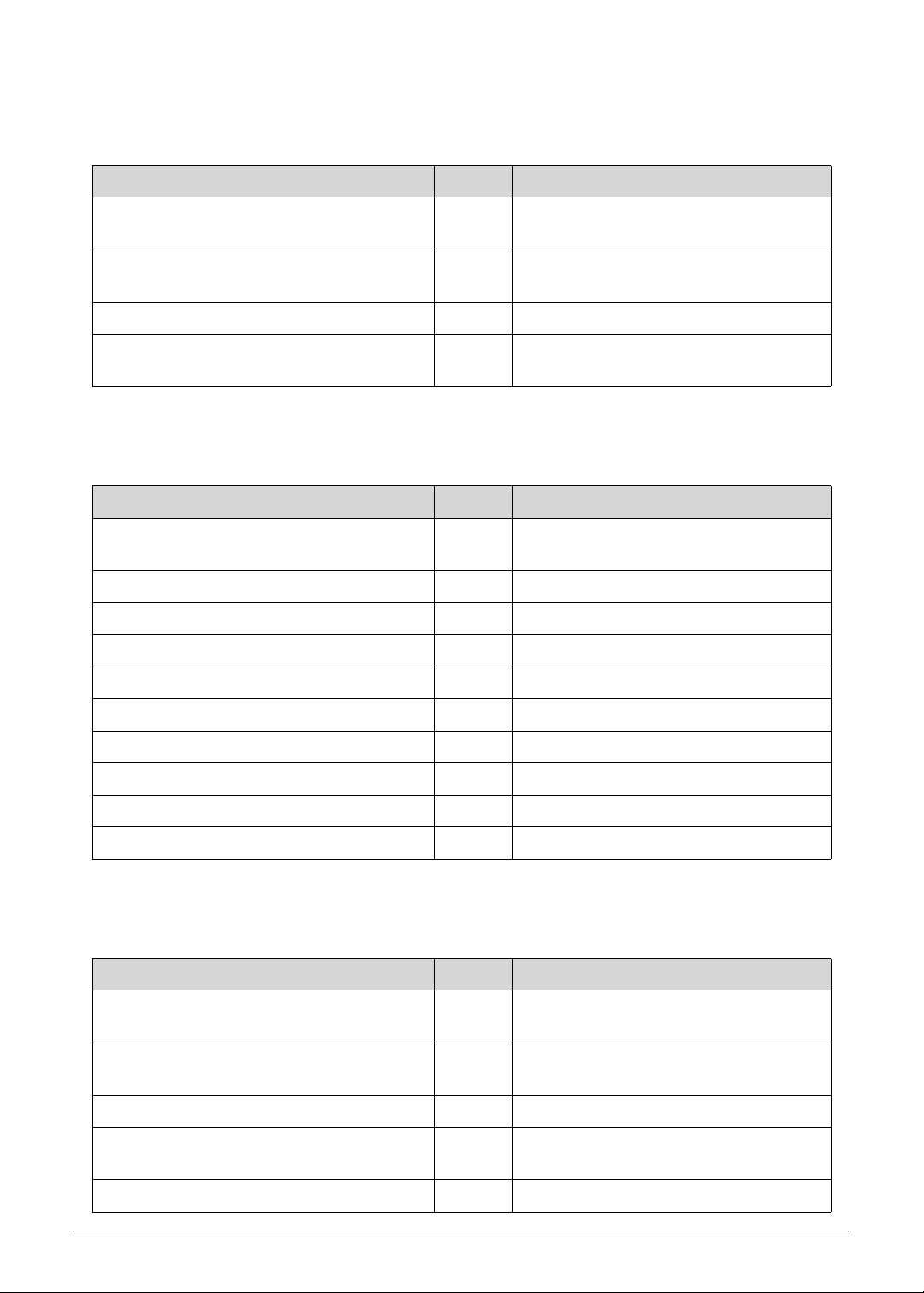
Troubleshooting 4-25
Table 4-6. PostBDS Functionality
Definition Code Description
#define POST_BDS_NO_BOOT_DEVICE 0xF9 No Boot Device,
PostBDS_NO_BOOT_DEVICE
#define POST_BDS_START_IMAGE 0xFB UEFI Boot Start Image,
PostBDS_START_IMAGE
#define POST_BDS_ENTER_INT19 0xFD Legacy 16 boot entry
#define
POST_BDS_JUMP_BOOT_SECTOR
0xFE Try to Boot with INT 19
Table 4-7. SMM Functionality
Definition Code Description
#define SMM_IDENTIFY_FLASH_
DEVICE
0xA0 Identify Flash device in SMM
#define SMM_SMM_PLATFORM_INIT 0xA2 SMM service initial
#define SMM_ACPI_ENABLE_START 0xA6 OS call ACPI enable function
#define SMM_ACPI_ENABLE_END 0xA7 ACPI enable function complete
#define SMM_S1_SLEEP_CALLBACK 0xA1 Enter S1
#define SMM_S3_SLEEP_CALLBACK 0xA3 Enter S3
#define SMM_S4_SLEEP_CALLBACK 0xA4 Enter S4
#define SMM_S5_SLEEP_CALLBACK 0xA5 Enter S5
#define SMM_ACPI_DISABLE_START 0xA8 OS call ACPI disable function
#define SMM_ACPI_DISABLE_END 0xA9 ACPI disable function complete
Table 4-8. S3 Functionality
Definition Code Description
#define S3_RESTORE_MEMORY_
CONTROLLER
0xC0 Memory initial for S3 resume
#define S3_INSTALL_S3_MEMORY 0xC1 Get S3 resume required data from
memory
#define S3_SWITCH_STACK 0xC2 Start to use memory during S3 resume
#define S3_MEMORY_CALLBACK 0xC3 Set cache for physical memory during
S3 resume
#define S3_ENTER_S3_RESUME_PEIM 0xC4 Start to restore system configuration
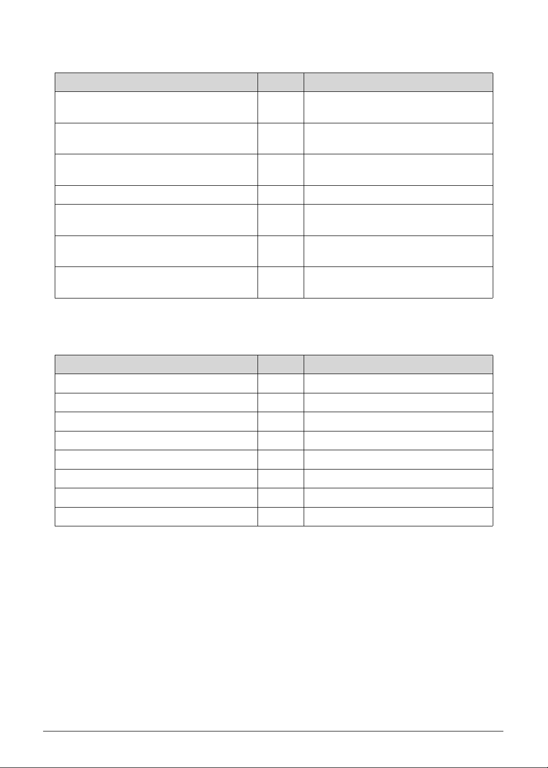
4-26 Troubleshooting
#define S3_BEFORE_ACPI_BOOT_
SCRIPT
0xC5 Restore system configuration stage 1
#define S3_BEFORE_RUNTIME_BOOT_
SCRIPT
0xC6 Restore system configuration stage 2
#define S3_BEFORE_RELOCATE_SMM_
BASE
0xC7 Relocate SMM BASE during S3 resume
#define S3_BEFORE_MP_INIT 0xC8 Multi-processor initial during S3 resume
#define S3_BEFORE_RESTORE_ACPI_
CALLBACK
0xC9 Start to restore system configuration in
SMM
#define S3_AFTER_RESTORE_ACPI_
CALLBACK
0xCA Restore system configuration in SMM
complete
#define S3_GO_TO_FACS_WAKING_
VECTOR
0xCB Back to OS
Table 4-9. ASL Functionality
Definition Code Description
#define ASL_ENTER_S1 0x51 Prepare to enter S1
#define ASL_ENTER_S3 0x53 Prepare to enter S3
#define ASL_ENTER_S4 0x54 Prepare to enter S4
#define ASL_ENTER_S5 0x55 Prepare to enter S5
#define ASL_WAKEUP_S1 0xE1 System wakeup from S1
#define ASL_WAKEUP_S3 0xE3 System wakeup from S3
#define ASL_WAKEUP_S4 0xE4 System wakeup from S4
#define ASL_WAKEUP_S5 0xE5 System wakeup from S5
Table 4-8. S3 Functionality (Continued)
Definition Code Description

CHAPTER 5
Jumper and Connector Locations

5-2
Mainboard Layout . . . . . . . . . . . . . . . . . . . . . . . . . . . . . . . . . . . . .5-3
Clearing Password Check and BIOS Recovery . . . . . . . . . . . . .5-5
Clearing the BIOS Passwords . . . . . . . . . . . . . . . . . . . . . . . . . .5-5
Performing a BIOS Recovery . . . . . . . . . . . . . . . . . . . . . . . . . .5-6
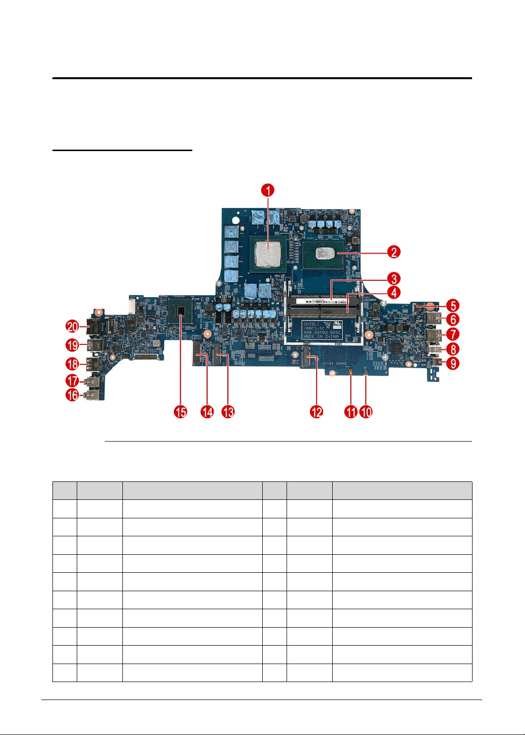
Jumper and Connector Locations 5-3
Jumper and Connector Locations
This chapter shows the mainboard layout and jumper locations of the Predator Triton 515-51
computer.
Mainboard Layout 0
Figure 5-1. Mainboard Top
Table 5-1. Mainboard Top
No. Code Component No. Code Component
1 VGA1 VGA 11 PWBTN1 Power button
2 CPU1 CPU 12 SSD2 SSD connector
3 DIMM2 DIMM slot 13 SSD1 SSD connector
4 DIMM1 DIMM slot 14 WLAN1 WLAN connector
5 FAN1 Fan cable connector 15 PCH1 Chipset
6 USB1 USB3.1 connector 16 HP1 Headphone connector
7 USB2 USB3.1 connector 17 MIC1 MIC connector
8 DP1 Display Port connector 18 HDMI1 HDMI connector
9 TYPEC1 USB Type-C connector 19 USB3 USB3.1 connector
10 RTC1 RTC battery cable connector 20 RJ45 LAN connector
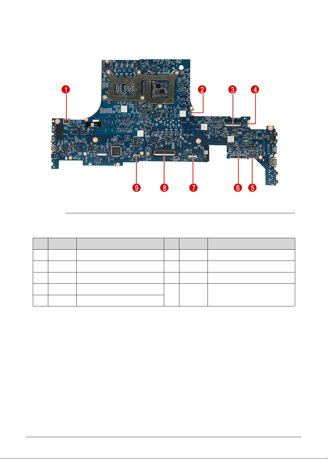
5-4 Jumper and Connector Locations
Figure 5-2. Mainboard Bottom
Table 5-2. Mainboard Bottom
No. Code Component No. Code Component
1 RESET1 System reset button 6 BTY1 Battery cable connector
2 TURBO1 Turbo key connector 7 TPAD1 Touchpad cable connector
3 EDP1 eDP cable connector 8 KB1 Keyboard cable connector
4 DCIN1 DC-In connector 9 KBBL1 Keyboard backlight cable
connector
5 SPK1 Speaker cable connector
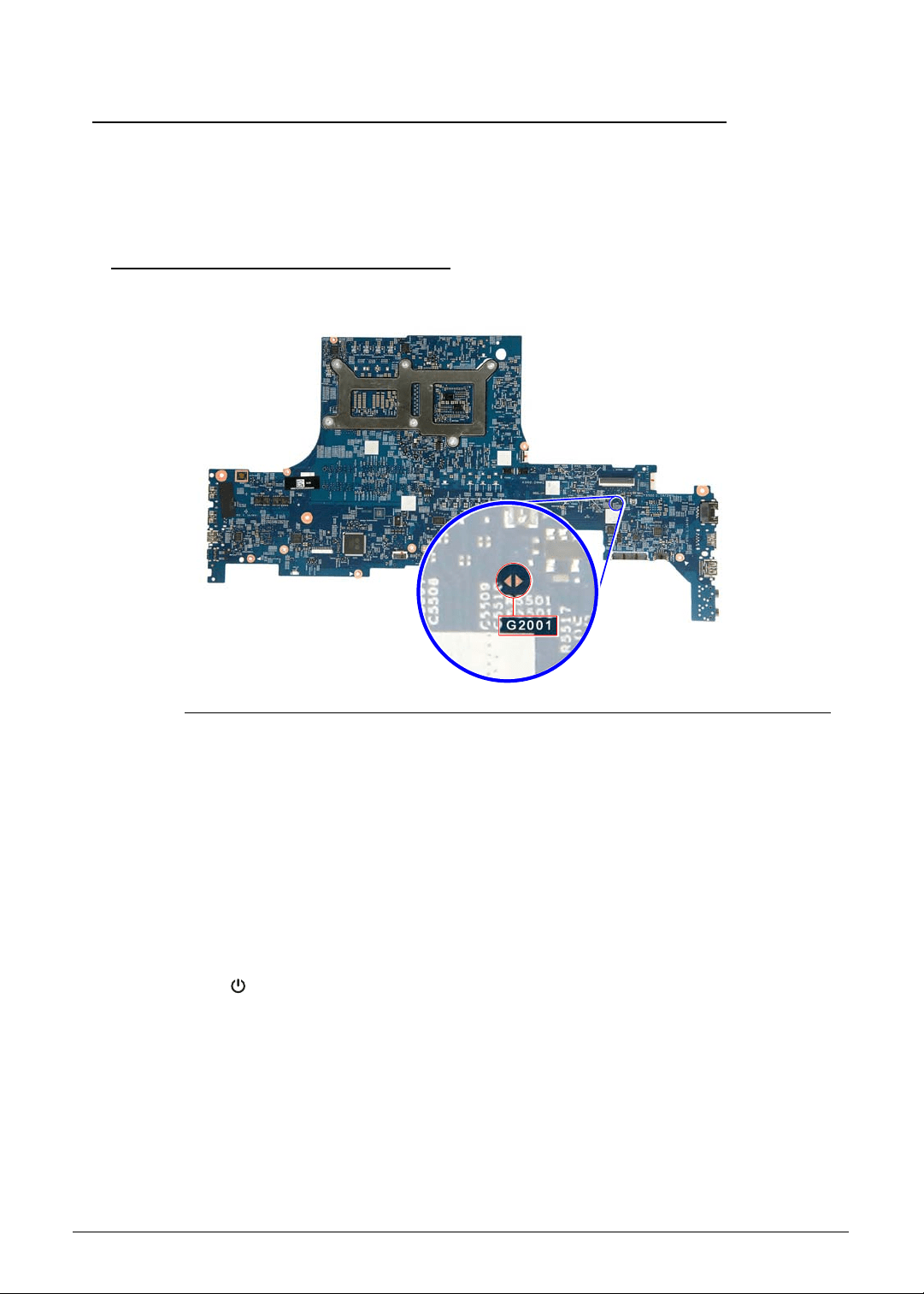
Jumper and Connector Locations 5-5
Clearing Password Check and BIOS Recovery 0
This section provides procedures for:
Clearing the BIOS passwords
Performing a BIOS recovery
Clearing the BIOS Passwords 0
To clear a lost BIOS password (user or supervisor password), you need to short the clear
password hardware gap (G2001) located on the mainboard.
Figure 5-3. G2001 Hardware Gap
1. Shut down the computer and disconnect the AC adapter and all other peripherals from the
computer.
2. Perform the “Removing the Lower Case” procedure described on page 3-9. Do not
disconnect the DC-In and LCD cables from the mainboard.
3. Perform the “Removing the Battery Pack” procedure described on page 3-11.
4. Locate the G2001 gap.
5. Use an electrical conductivity tool to short the two contacts on the hardware gap together.
6. While resting the tool on the two contacts, plug one end of the AC adapter into the DC-In
jack and plug one end to an electrical outlet.
7. Press the button to turn on the computer.
8. After the BIOS POST, remove the tool from the hardware gap.
9. Perform the “Replacing the Battery Pack” procedure described on page 3-82.
10. Perform the “Replacing the Lower Case” procedure described on page 3-84.
11. Turn on the computer and press F2 during bootup to access the Setup Utility. If no
password prompt appears, the BIOS passwords have been cleared. If the prompt
appears, repeat steps 2-13 until the BIOS passwords have been cleared.
12. Press F9 to load the system defaults.
13. Press F10 to save the changes you made and close the Setup Utility.

5-6 Jumper and Connector Locations
Performing a BIOS Recovery 0
Boot Block 0
An interruption during a BIOS flash procedure (e.g. a power outage) can corrupt the BIOS
code, which will cause the system to go into an unbootable state. The BIOS boot block refers
to a special BIOS program that can be used to boot up a system with minimum BIOS
initialization.You need to access and execute the boot block to reboot the computer and
recover the regular BIOS code.
Creating the Crisis Disk 0
NOTE:
NOTE:
The BIOS crisis recovery disk should be prepared in a computer running the Windows
OS. A USB flash drive can be used.
All data in the USB flash drive will be cleared during the creation of the crisis disk.
1. Prepare a removable USB flash drive.
2. Transfer the BIOS.fd file in the USB flash drive’s root directory.
3. Eject and reconnect the USB flash drive from the computer.
Performing a BIOS recovery 0
NOTE:
NOTE:
Make sure the battery pack is installed to the system and that the computer is
connected to a UPS unit during the BIOS recovery process.
The function hotkey sequence Fn+Esc is used to enable the BIOS recovery process when
system is powered On during BIOS POST. If this function is enabled, the system will force the
BIOS to execute the boot block program.
To perform a BIOS recovery:
1. Shut down the BIOS failed-computer.
2. Connect the USB flash drive containing the Crisis Recovery disk files to the computer.
3. Press and hold the Fn+Esc keys, then press the power button .
The BIOS recovery process begins. When the process is complete the computer will
automatically reboot.
4. Disconnect the USB flash drive from the computer.
5. Perform a BIOS flash procedure to update the BIOS firmware. Refer to the “BIOS Flash
Utilities” section on page 2-15 for detailed instructions.

CHAPTER 6
FRU List

6-2
Predator Triton 515-51 Exploded Diagrams . . . . . . . . . . . . . . . .6-4
Main Assembly . . . . . . . . . . . . . . . . . . . . . . . . . . . . . . . . . . . . .6-4
LCD Assembly. . . . . . . . . . . . . . . . . . . . . . . . . . . . . . . . . . . . . .6-5
Predator Triton 515-51 FRU List . . . . . . . . . . . . . . . . . . . . . . . . .6-6

FRU (Field Replaceable Unit) List 6-3
FRU (Field Replaceable Unit) List
This chapter provides users with a FRU (Field Replaceable Unit) listing in global
configurations for the Predator Triton 515-51. Refer to this chapter whenever ordering for
parts to repair or for RMA (Return Merchandise Authorization).
NOTE:
NOTE:
WHEN ORDERING FRU PARTS, check the most up-to-date information available on
the regional web or channel. Part number changes will not be noted on the printed
Service Guide. For ACER AUTHORIZED SERVICE PROVIDERS, the Acer office may
have a DIFFERENT part number code from those given in the FRU list of this printed
Service Guide. Users MUST use the local FRU list provided by the regional Acer office
to order FRU parts for repair and service of customer machines.
NOTE:
NOTE:
To scrap or to return the defective parts, users should follow the local government
ordinance or regulations on how to dispose it properly, or follow the rules set by the
regional Acer office on how to return it.
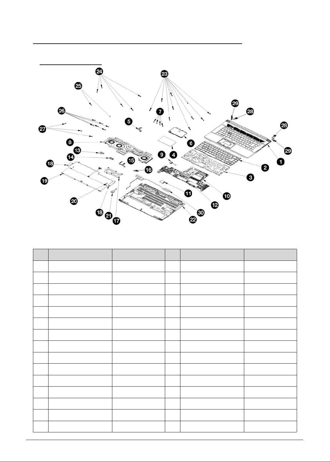
6-4 FRU (Field Replaceable Unit) List
Predator Triton 515-51 Exploded Diagrams 0
Main Assembly 0
Figure 6-1. Main Assembly Exploded Diagram
Table 6-1. Main Assembly Exploded Diagram
No. Description Part Number No. Description Part Number
1 Upper Case Assy 460.0GY04.0001 16 Turbo Key Screw 86.4A362.3R0
2 KB Module 46M.0GYCS.0001 17 CPU/GPU Bracket 460.0GY08.0001
3 KB Bracket Assy 460.0GY05.0001 18 Speaker 023.400HN.0001
4 TP Mylar 440.0GY07.0001 19 Battery Module KT.00408.001
5 TP Cable 450.0GY01.0001 20 Battery Screw 86.00E13.524
6 TP Module 46M.0GYPD.0002 21 RTC Battery 23.25207.032
7 TP Screw 86.00R69.322 22 Lower Case Assy 460.0GY09.0001
8 Thermal Module 460.0GY01.0001 23 Screw 08A.00000.0099
9 DC-In Module 450.0GY02.0001 24 MB Screw 86.00E13.524
10 Mainboard NB.Q5011.001 25 Thermal Fan Screw 86.00E13.524
11 WLAN Module KE.11A0N.013 26 Thermal Screw 86.00E13.524
12 SSD Module KN.2560D.011 27 WIFI/SSD Screw 86.00E13.524
13 Turbo Key Bracket 433.0GY04.0001 28 Hinge Screw (Flap) 86.00R69.322
14 Turbo Key Module 46M.0GYBD.0001 29 Hinge Screw 86.00R69.322
15 Turbo Key Cable 450.0GY03.0001 30 WLAN Antenna 025.90110.0001
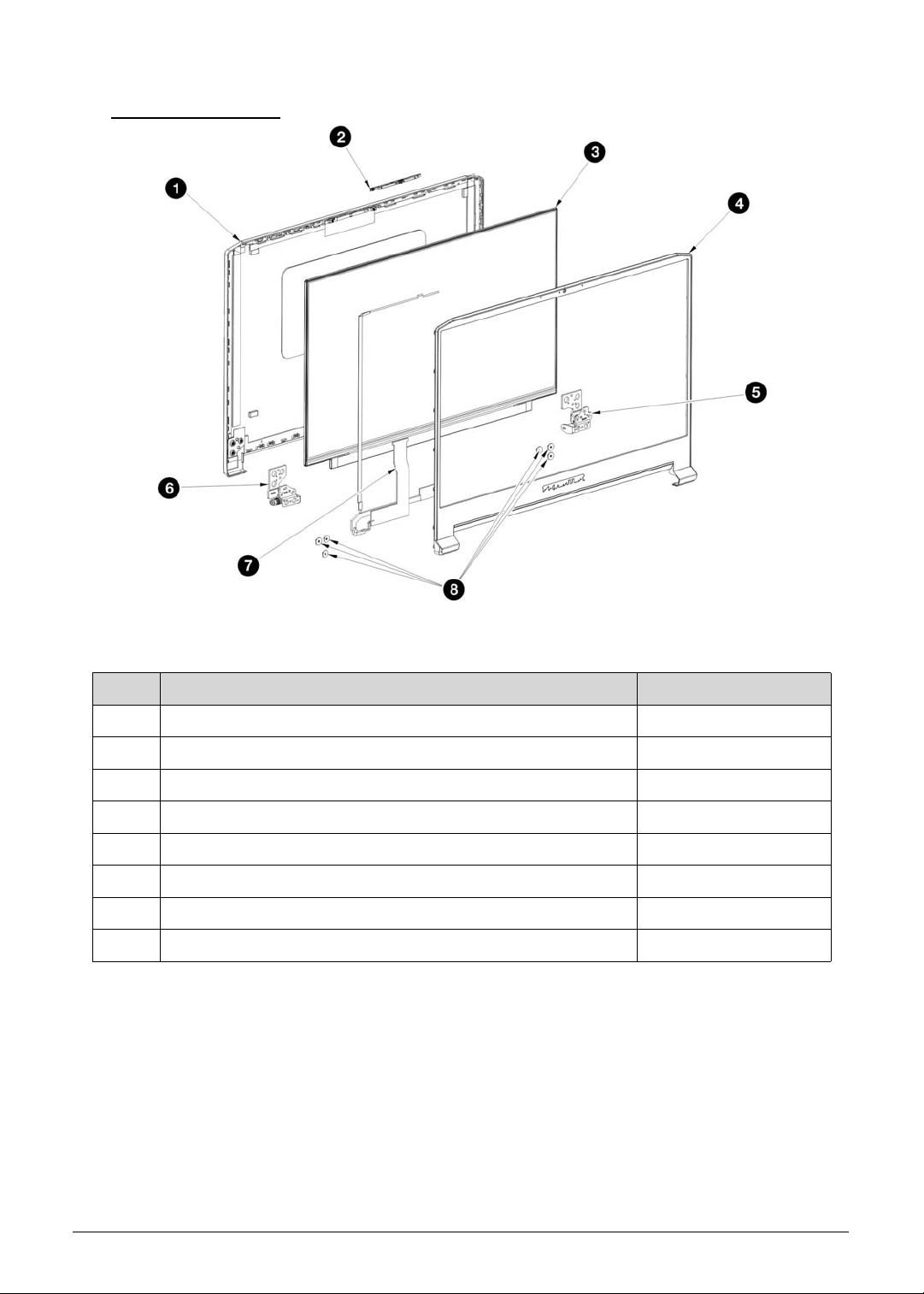
FRU (Field Replaceable Unit) List 6-5
LCD Assembly 0
Figure 6-2. LCD Assembly Exploded Diagram
Table 6-2. LCD Assembly Exploded Diagram
No. Description Part Number
1 LCD back cover 460.0GY02.0001
2 Camera KS.0HD05.013
3 LCD panel KL.1560E.016
4 LCD bezel 460.0GY03.0001
5 LCD right hinge bracket 460.0GY02.0001
6 LCD left hinge bracket 433.0GY02.0001
7 LCD eDP/webcam cable 450.0GY04.0001
7 Hinge Screw 86.9AR13.2R5
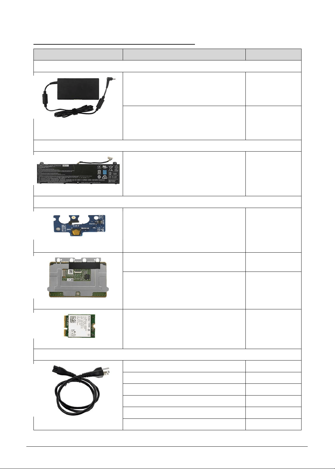
6-6 FRU (Field Replaceable Unit) List
Predator Triton 515-51 FRU List 0
Category Description Acer Part No.
ADAPTER
ADAPTER DELTA 180W 19.5V
1.7X5.5X11 ADP-180TB FC LF BLACK
SLIMT TYPE. MEET COC TIER 2 / IEC
62368
KP.18001.006
ADAPTER CHICONY POWER 180W
19.5V 1.7X5.5X11 A180A034P LF BLACK
SLIMT TYPE. MEET COC TIER 2 / IEC
62368
KP.1800H.001
BATTERY
BATTERY GETAC AP18J POLYMER
4S1P HIGHPOWER 4 CELL 5400MAH
MAIN COMMON BNS, GETAC
KT.00408.001
BOARDS
TURBO KEY BOARD 55.Q50N1.001
ASSEMBLY TOUCHPAD SYNAPTICS
NC.24611.04S W/MYLAR BLACK
56.Q50N1.001
ASSEMBLY TOUCHPAD ELANTECH
NC.24611.04E W/MYLAR BLACK
56.Q50N1.002
WIRELESS LAN INTEL 802.11AC
BLUETOOTH FM KILLER WIRELESS
1550I INT9560.NGWG.NV
KE.11A0N.013
CABLES
POWER CORD 125V US BK 1M 27.RSF01.001
POWER CORD 250V EUROPE BK 1M 27.RSF01.002
POWER CORD 250V UK BK 1M 27.RSF01.003
POWER CORD 250V DENMARK BK 1M 27.RSF01.004
POWER CORD 250V SWISS BK 1M 27.RSF01.005
POWER CORD 250V ITALY BK 1M 27.RSF01.006
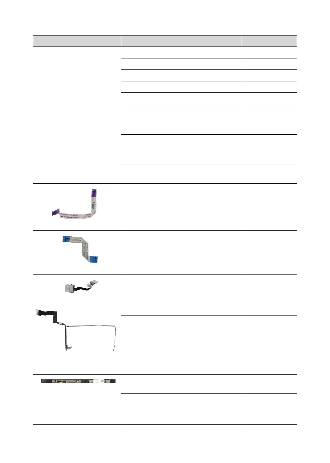
FRU (Field Replaceable Unit) List 6-7
Power Cord
(Cont.)
POWER CORD 250V CHINA BK 1M 27.RSF01.007
POWER CORD 125V TAIWAN BK 1M 27.RSF01.008
POWER CORD 125V JAPAN BK 1M 27.RSF01.009
POWER CORD 250V KOREA BK 1M 27.RSF01.010
POWER CORD 250V ISRAEL BK 1M 27.RSF01.011
POWER CORD 250V ARGENTINE BK
1M
27.RSF01.012
POWER CORD 250V BRAZIL BK 1M 27.RSF01.013
POWER CORD 250V SOUTH AFRICA
BK 1M
27.RSF01.015
POWER CORD 250V AUSTRALIA BK 1M 27.RSF01.016
POWER CORD 250V AFRICA-S INDIA
BK 1M
27.VL0D1.001
FFC CABLE - TURBO KEY BOARD 33.Q50N1.001
FFC CABLE - TOUCHPAD 50.Q50N1.001
DC IN CABLE - 180W 50.Q50N1.002
EDP LCD CABLE FOR BOE LCD 50.Q50N1.003
EDP LCD CABLE FOR AUO LCD 50.Q50N1.004
CAMERA
CAMERA LITEON HD CAMERA
7BF115N2 (ADD MIC*2)
KS.0HD05.013
CAMERA CHICONY HD CAMERA
CH_OV9734_RTS5846W_AOET_KMM35
20 UNIFIED2 (ADD MIC*2)
KS.0HD06.009
Category Description Acer Part No.
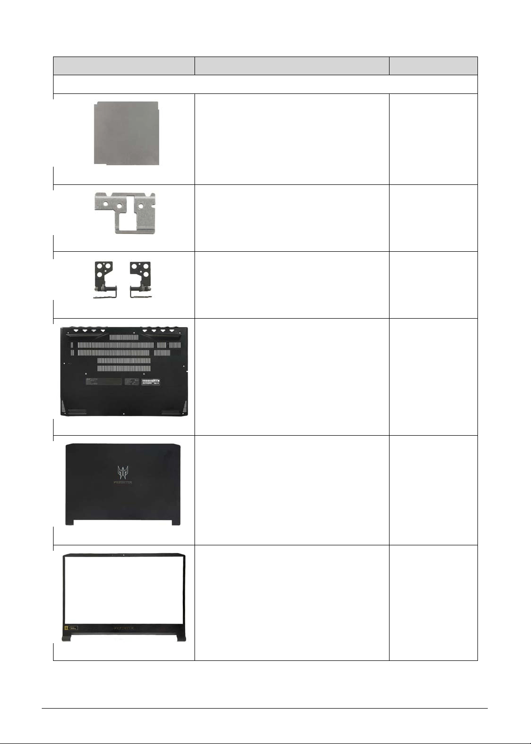
6-8 FRU (Field Replaceable Unit) List
CASE/COVER/BRACKET ASSEMBLY
MEMORY SHIELDING 33.Q50N1.002
TURBO KEY BOARD BRACKET 33.Q50N1.003
LCD HINGE LEFT & RIGHT KITTING 33.Q50N1.004
LOWER CASE 15.6" BLACK 60.Q50N1.001
LCD COVER 15.6" BLACK W/
PREDATOR LOGO
60.Q50N1.002
LCD BEZEL 15.6" BLACK W/ CAMERA
HOLE & PREDATOR LOGO
60.Q50N1.003
Category Description Acer Part No.
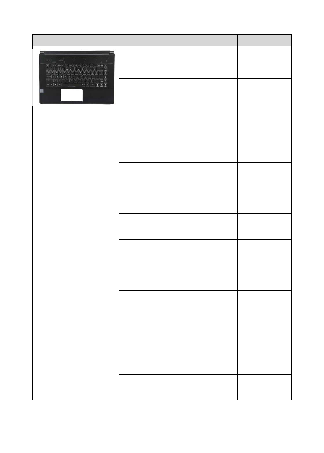
FRU (Field Replaceable Unit) List 6-9
ASSEMBLY 15.6" UPPER CASE BLACK
W/ANTENNA*2 & BL KB LG4P_P90BRL
86KS BLACK ALA-SPANISH
NK.I1417.0NE
6B.Q50N1.001
ASSEMBLY 15.6" UPPER CASE BLACK
W/ANTENNA*2 & BL KB LG4P_P90BRL
85KS BLACK ARABIC NK.I1417.0N2
6B.Q50N1.002
ASSEMBLY 15.6" UPPER CASE BLACK
W/ANTENNA*2 & BL KB LG4P_P90BRL
86KS BLACK BELGIUM NK.I1417.0NF
6B.Q50N1.003
ASSEMBLY 15.6" UPPER CASE BLACK
W/ANTENNA*2 & BL KB LG4P_P90BRL
86KS BLACK BRAZILIAN PORTUGUESE
NK.I1417.0NG
6B.Q50N1.004
ASSEMBLY 15.6" UPPER CASE BLACK
W/ANTENNA*2 & BL KB LG4P_P90BRL
86KS BLACK CZ/SK NK.I1417.0NH
6B.Q50N1.005
ASSEMBLY 15.6" UPPER CASE BLACK
W/ANTENNA*2 & BL KB LG4P_P90BRL
86KS BLACK DANISH NK.I1417.0NJ
6B.Q50N1.006
ASSEMBLY 15.6" UPPER CASE BLACK
W/ANTENNA*2 & BL KB LG4P_P90BRL
86KS BLACK FR/ARABIC NK.I1417.0NK
6B.Q50N1.007
ASSEMBLY 15.6" UPPER CASE BLACK
W/ANTENNA*2 & BL KB LG4P_P90BRL
86KS BLACK FRENCH NK.I1417.0NL
6B.Q50N1.008
ASSEMBLY 15.6" UPPER CASE BLACK
W/ANTENNA*2 & BL KB LG4P_P90BRL
86KS BLACK GERMAN NK.I1417.0NM
6B.Q50N1.009
ASSEMBLY 15.6" UPPER CASE BLACK
W/ANTENNA*2 & BL KB LG4P_P90BRL
85KS BLACK GREEK NK.I1417.0N4
6B.Q50N1.010
ASSEMBLY 15.6" UPPER CASE BLACK
W/ANTENNA*2 & BL KB LG4P_P90BRL
86KS BLACK HUNGARIAN
NK.I1417.0NN
6B.Q50N1.011
ASSEMBLY 15.6" UPPER CASE BLACK
W/ANTENNA*2 & BL KB LG4P_P90BRL
86KS BLACK ITALIAN NK.I1417.0NP
6B.Q50N1.012
ASSEMBLY 15.6" UPPER CASE BLACK
W/ANTENNA*2 & BL KB LG4P_P90BRL
85KS BLACK KOREAN NK.I1417.0N5
6B.Q50N1.013
Category Description Acer Part No.

6-10 FRU (Field Replaceable Unit) List
Upper Case + KB
(Cont.)
ASSEMBLY 15.6" UPPER CASE BLACK
W/ANTENNA*2 & BL KB LG4P_P90BRL
86KS BLACK NORDIC NK.I1417.0NQ
6B.Q50N1.014
ASSEMBLY 15.6" UPPER CASE BLACK
W/ANTENNA*2 & BL KB LG4P_P90BRL
86KS BLACK NORWEGIAN
NK.I1417.0NR
6B.Q50N1.015
ASSEMBLY 15.6" UPPER CASE BLACK
W/ANTENNA*2 & BL KB LG4P_P90BRL
85KS BLACK PERSIAN NK.I1417.0N8
6B.Q50N1.016
ASSEMBLY 15.6" UPPER CASE BLACK
W/ANTENNA*2 & BL KB LG4P_P90BRL
86KS BLACK PORTUGUESE
NK.I1417.0NS
6B.Q50N1.017
ASSEMBLY 15.6" UPPER CASE BLACK
W/ANTENNA*2 & BL KB LG4P_P90BRL
85KS BLACK RUSSIAN NK.I1417.0N6
6B.Q50N1.018
ASSEMBLY 15.6" UPPER CASE BLACK
W/ANTENNA*2 & BL KB LG4P_P90BRL
86KS BLACK SLO/CRO NK.I1417.0NT
6B.Q50N1.019
ASSEMBLY 15.6" UPPER CASE BLACK
W/ANTENNA*2 & BL KB LG4P_P90BRL
86KS BLACK SPANISH NK.I1417.0NU
6B.Q50N1.020
ASSEMBLY 15.6" UPPER CASE BLACK
W/ANTENNA*2 & BL KB LG4P_P90BRL
86KS BLACK SWEDEN NK.I1417.0NV
6B.Q50N1.021
ASSEMBLY 15.6" UPPER CASE BLACK
W/ANTENNA*2 & BL KB LG4P_P90BRL
86KS BLACK SWISS/G NK.I1417.0NW
6B.Q50N1.022
ASSEMBLY 15.6" UPPER CASE BLACK
W/ANTENNA*2 & BL KB LG4P_P90BRL
85KS BLACK THAILAND NK.I1417.0N9
6B.Q50N1.023
ASSEMBLY 15.6" UPPER CASE BLACK
W/ANTENNA*2 & BL KB LG4P_P90BRL
85KS BLACK TRADITIONAL CHINESE
NK.I1417.0N3
6B.Q50N1.024
ASSEMBLY 15.6" UPPER CASE BLACK
W/ANTENNA*2 & BL KB LG4P_P90BRL
86KS BLACK TURKISH NK.I1417.0NX
6B.Q50N1.025
ASSEMBLY 15.6" UPPER CASE BLACK
W/ANTENNA*2 & BL KB LG4P_P90BRL
86KS BLACK UK NK.I1417.0NY
6B.Q50N1.026
Category Description Acer Part No.
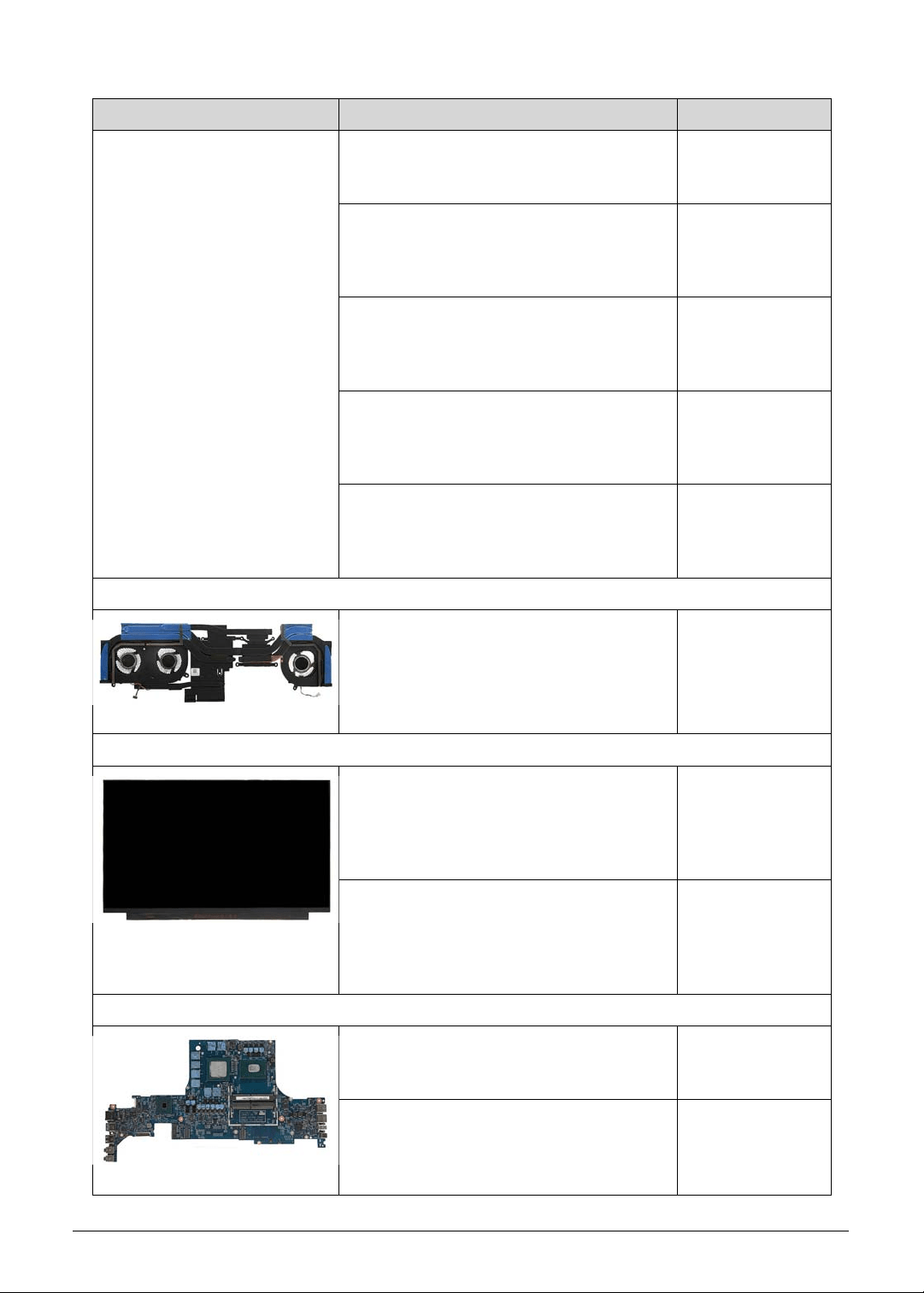
FRU (Field Replaceable Unit) List 6-11
Upper Case + KB
(Cont.)
ASSEMBLY 15.6" UPPER CASE BLACK
W/ANTENNA*2 & BL KB LG4P_P90BRL
85KS BLACK UKRAINIAN NK.I1417.0N7
6B.Q50N1.027
ASSEMBLY 15.6" UPPER CASE BLACK
W/ANTENNA*2 & BL KB LG4P_P90BRL
85KS BLACK US INTERNATIONAL
NK.I1417.0NA
6B.Q50N1.028
ASSEMBLY 15.6" UPPER CASE BLACK
W/ANTENNA*2 & BL KB LG4P_P90BRL
85KS BLACK US INTERNATIONAL W/
BULGARIA NK.I1417.0ND
6B.Q50N1.029
ASSEMBLY 15.6" UPPER CASE BLACK
W/ANTENNA*2 & BL KB LG4P_P90BRL
85KS BLACK US INTERNATIONAL W/
CANADIAN FRENCH NK.I1417.0NC
6B.Q50N1.030
ASSEMBLY 15.6" UPPER CASE BLACK
W/ANTENNA*2 & BL KB LG4P_P90BRL
85KS BLACK US INTERNATIONAL W/
HEBREW NK.I1417.0NB
6B.Q50N1.031
HEATSINK
THERMAL W/FAN - DIS SKU 24.Q50N1.001
LCD
LED LCD PANEL AUO 15.6"W FHD
NONE GLARE B156HAN08.2 H/W 7A LF
300NIT 9MS 800:1 (EDP,IPS,144HZ,OD
3MS GTG,NARROW BORDER,2.6T
MAX)
KL.15605.053
LED LCD PANEL BOE 15.6"W FHD
NONE GLARE NV156FHM-N4K LF
300NIT 9MS 1200:1 (EDP,IPS,144HZ,OD
3MS GTG,NARROW BORDER,2.6T
MAX)
KL.1560E.016
MAINBOARD
MAINBOARD PT515-51_N18EG3 W/CPU
INTEL CI78750H & MEM 8GB & RTC
BATTERY SUPPORT 180W ADAPTER
NB.Q4W11.001
MAINBOARD PT515-51_N18EG2 W/CPU
INTEL CI78750H & MEM 8GB & RTC
BATTERY SUPPORT 180W ADAPTER
NB.Q4X11.001
Category Description Acer Part No.
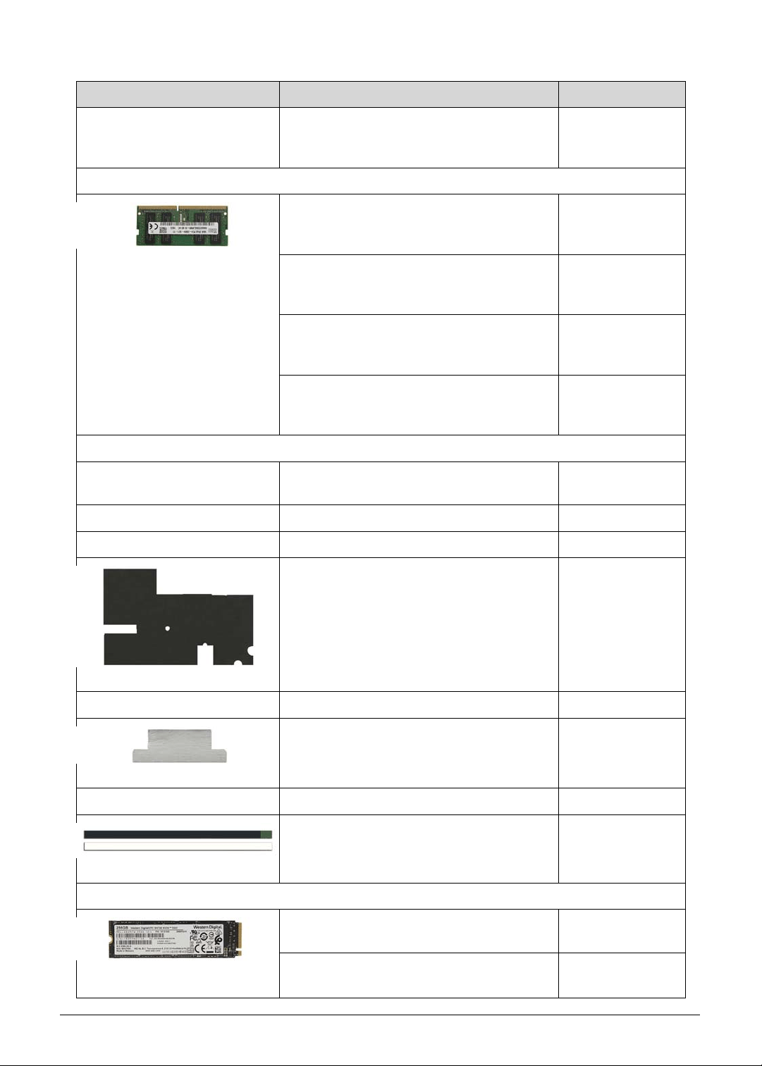
6-12 FRU (Field Replaceable Unit) List
Mainboard
(Cont.)
MAINBOARD PT515-51_N18EG1 W/CPU
INTEL CI78750H & MEM 6GB & RTC
BATTERY SUPPORT 180W ADAPTER
NB.Q5011.001
MEMORY
MEMORY KINGSTON SO-DIMM DDRIV
2666 16GB ACR26D4S9D8ME-16 LF+HF
1024*8
KN.16G07.028
MEMORY HYNIX SO-DIMM DDRIV 2666
16GB HMA82GS6CJR8N-VK LF+HF
1024*8 1XNM, AL
KN.16G0G.031
MEMORY KINGSTON SO-DIMM DDRIV
2666 8GB ACR26D4S9S8ME-8 LF+HF
1024*8
KN.8GB07.042
MEMORY HYNIX SO-DIMM DDRIV 2666
8GB HMA81GS6CJR8N-VK LF+HF
1024*8 1XNM, AL
KN.8GB0G.058
MISCELLANEOUS
LCD MYLAR - FOR SERVICE LCD
ALIGNMENT
47.H46N1.001
MIC RUBBER 47.Q50N1.001
EMI GASKET TAPE 47.Q50N1.002
GRAPHITE MYLAR - UPPERCASE 47.Q50N1.003
TAPE - CABLE FIX 47.Q50N1.004
CONDUCTIVE TAPE - MEMORY
SHIELDING
47.Q50N1.005
CONDUCTIVE TAPE - RF 47.Q50N1.006
ADHESIVE TAPE - LCD PANEL
SERVICE GHIBLI
47.Q50N1.007
SSD/SOLID STATE DRIVE
FLASH DISK SANDISK SSD NAND
256GB SDAPNTW-256G-1014 LF+HF
KN.2560D.011
FLASH DISK SANDISK SSD NAND
512GB SDAPNTW-512G-1014 LF+HF
KN.5120D.005
Category Description Acer Part No.
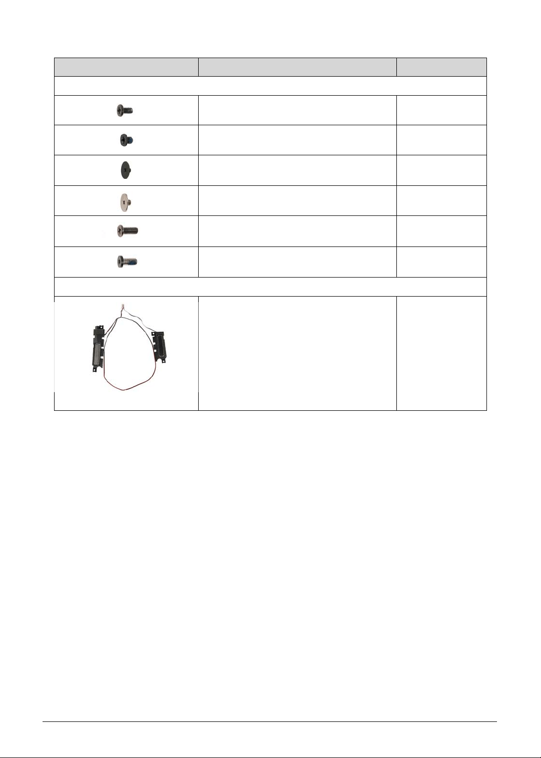
FRU (Field Replaceable Unit) List 6-13
SCREWS
SCREW, WAF M24 BZNYLOK CR3+ 86.00E92.724
SCREW, M2XL2.5 T0.5 D4/BLACK 86.M92N1.005
SCREW, M2XL2 T0.35 D7 GL
ZN+NYLOK
86.MQJN1.001
SCREW, M2.5XL2.5, T0.6 D8.0 86.MQJN1.003
SCREW M2.5 L6.0 BLACK NICKEL
NYLOK
86.MVAN1.002
SCREW M2.5 L6.0 BLACK NICKEL
NYLOK
86.Q50N1.001
SPEAKER
SPEAKER 23.Q50N1.001
Category Description Acer Part No.

6-14 FRU (Field Replaceable Unit) List

CHAPTER 7
Test Compatible Components

Test Compatible Components 7-3
Test Compatible Components
This computer" s compatibility is tested and verified by Acer" s internal testing department. All
of its system functions are tested under Windows
®
10 environment.
Refer to the following lists for components, adapter cards, and peripherals which have passed
these tests. Regarding configuration, combination and test procedures, please refer to the
Compatibility Test Report released by the Acer Mobile System Testing Department.
Microsoft Windows 10 Environment Test 0
Vendor Type Description Part No.
A cover
10553782
JUTENG
(NEIJIANG)
COMM.
Abyssal Black
15 AL
Anodizing
JUTENG (NEIJIANG) A cover Abyssal
Black 15 AL Anodizing
NC.21011.0Q7
Adapter
60035715
DELTA-
SINGAPORE
180W_5.5phy -
Slim
Adapter DELTA 180W 19.5V 1.7x5.5x11
ADP-180TB FC LF Black Slimt type.
Meet CoC Tier 2 / IEC 62368
KP.18001.006
60016453
CHICONY
POWER
180W_5.5phy -
Slim
Adapter Chicony Power 180W 19.5V
1.7x5.5x11 A180A034P LF Black Slim
type. Meet CoC Tier 2 / IEC 62368
KP.1800H.001
Audio Codec
10004786
REALTEK
Audio Codec Non-AVAP Audio Codec - Realtek
ALC289 (HDA) WW
NC.21011.0PS
B cover
10000286
WISTRON
Abyssal Black
15 PC+ABS
Painting w/
Camera
WISTRON B cover Abyssal Black 15
PC+ABS Painting w/ Camera
NC.21011.0Q8
Battery
60036496
GETAC
TECH.
CORP.
4CELL5.4 Battery Getac AP18J Polymer 4S1P
Highpower 4 cell 5400mAh Main
COMMON BnS, Getac
KT.00408.001
C cover
10553782
JUTENG
(NEIJIANG)
COMM.
Abyssal Black
15 AL
Anodizing
UTENG (NEIJIANG) C cover Abyssal
Black 15 AL Anodizing
NC.21011.0Q9

7-4 Test Compatible Components
Camera
60063681
LUXVISIONS
HD_Mic2_Unifi
ed_Narrow
Camera LITEON HD Camera
7BF115N2 (add Mic*2)
KS.0HD05.013
10001044
CHICONY
HD_Mic2_Unifi
ed_Narrow
Camera CHICONY HD Camera
CH_OV9734_RTS5846W_AOET_KMM
3520 Unified2 (add Mic*2)
KS.0HD06.009
CPU
10001067
INTEL
Ci58300H CPU(BGA) Intel Core i5 i5-8300H BGA
2.3G Coffee Lake
KC.83001.H00
10001067
INTEL
Ci78750H CPU(BGA) Intel Core i7 i7-8750H BGA
2.3G Coffee Lake L3 Cache 9M
KC.87501.H00
D cover
10553782
JUTENG
(NEIJIANG)
COMM.
Abyssal Black
15 AL
Anodizing
JUTENG (NEIJIANG) D cover Abyssal
Black 15 AL Anodizing
NC.21011.0QA
HDD
60058983
SANDISK
F80256PMP Flash Disk SANDISK SSD NAND
256GB SDAPNTW-256G-1014 LF+HF
KN.2560D.011
60058983
SANDISK
F80512PMP Flash Disk SANDISK SSD NAND
512GB SDAPNTW-512G-1014 LF+HF
KN.5120D.005
2nd HDD
60058983
SANDISK
F80256PMP Flash Disk SANDISK SSD NAND
256GB SDAPNTW-256G-1014 LF+HF
KN.2560D.011
60058983
SANDISK
F80512PMP Flash Disk SANDISK SSD NAND
512GB SDAPNTW-512G-1014 LF+HF
KN.5120D.005
Keyboard
60004864
DARFON
LG4P_P90BRL Phantom KB DARFON LG4P_P90BRL
LG4P Internal 14 Standard Black
Predator Sense+Power+Dish RGB
3-Zone BL
NK.I1417.0N1
LAN
60002823
HONG TECH
KILLER LAN
E3000
Killer Ethernet LAN E3000 2.5Gb
10*10mm, Rivet, Realtek Dragon LAN
IC
NA.22411.00E
LCD
10001022
INNOLUX
N15.6FHDSSP
IB
LED LCD Panel CMI 15.6W FHD None
Glare N156HCE-EN1 LF 300nit 25ms
700:1 (eDP, IPS, narrow border, 2.6mm
max)
KL.1560D.039
Vendor Type Description Part No.

Test Compatible Components 7-5
60003316
AUO
N15.6FHDSSR
IY2B
LED LCD Panel AUO 15.6'W FHD
None Glare B156HAN08.2 H/W 7A LF
300nit 9ms 800:1 (eDP,IPS,144Hz,OD
3ms GTG,narrow border,2.6t max)
KL.15605.053
60038572
BOE(HK)
N15.6FHDSSR
IY2B
LED LCD Panel BOE 15.6'W FHD None
Glare NV156FHM-N4K LF 300nit 9ms
1200:1 (eDP,IPS,144Hz,OD 3ms
GTG,narrow border,2.6t max)
KL.1560E.016
MEM
10000981
MISC
SO16GBIV Memory SO-DIMM DDRIV 16GB
Dummy LF+HF
KN.16G00.002
60024207
KINGSTON-F
AR EAST
SO16GBIV Memory KINGSTON SO-DIMM DDRIV
2666 16GB ACR26D4S9D8ME-16
LF+HF 1024*8
KN.16G07.028
60002045 SK
HYNIX
SO16GBIV Memory HYNIX SO-DIMM DDRIV 2666
16GB HMA82GS6CJR8N-VK LF+HF
1024*8 1Xnm, AL
KN.16G0G.031
10000981
MISC
SO16GBIV26 Memory SO-DIMM DDRIV 2666 16GB
Dummy LF+HF Dummy
KN.16G00.013
10000981
MISC
SO8GBIV Memory SO-DIMM DDRIV 8GB Dummy
LF+HF
KN.8GB00.010
60024207
KINGSTON-F
AR EAST
SO8GBIV Memory KINGSTON SO-DIMM DDRIV
2666 8GB ACR26D4S9S8ME-8 LF+HF
1024*8
KN.8GB07.042
60002045 SK
HYNIX
SO8GBIV Memory HYNIX SO-DIMM DDRIV 2666
8GB HMA81GS6CJR8N-VK LF+HF
1024*8 1Xnm, AL
KN.8GB0G.058
10000981
MISC
SO8GBIV26 Memory SO-DIMM DDRIV 2666 8GB
Dummy LF+HF Dummy
KN.8GB00.023
NB Chipset
10001067
INTEL
HM370 NB Chipset Intel CS HM370 KI.37001.HM0
Packaging
60059923
SEN HSIN
2019-Color-Gift
-15
2019 Color Gift 15 SY Rev 1.0 NC.25811.0JY
Touchpad
60040786
ELANTECH
CP4WIP3M Elantec Touchpad CP4WIP3M PTP
SA464C-12A0 104x64mm PCB
(Moisture)
NC.24611.04E
60040547
SYNAPTICS
CP4WIP3M Synaptics Touchpad CP4WIP3M PTP
TM-P3392-002 104x64mm PCB
(Moisture+MSB)
NC.24611.04S
Vendor Type Description Part No.

7-6 Test Compatible Components
VGA Chip
60001915
NVIDIA
N18E-G1-KD-A
1
VGA Chip nVidia N18E-G1-KD-A1
N18E-G1-KD-A1 GB4-256,
37.5x37.5mm, 16nm,192bit
KG.EG10V.005
60001915
NVIDIA
N18E-G1-KD-
QS-A1
VGA Chip nVidia N18E-G1-KD-QS-A1
N18E-G1-KD-QS-A1 GB4-256,
37.5x37.5mm, 16nm,192bit
KG.EG10V.004
60001915
NVIDIA
N18E-G2-A1 VGA Chip nVidia N18E-G2-A1
N18E-G2-A1
KG.EG20V.003
60001915
NVIDIA
N18E-G2-QS-A
1
VGA Chip nVidia N18E-G2-QS-A1
N18E-G2-QS-A1
KG.EG20V.002
60001915
NVIDIA
N18E-G3-A1 VGA Chip nVidia N18E-G3-A1
N18E-G3-A1
KG.EG30V.004
60001915
NVIDIA
N18E-G3-QS-A
1
VGA Chip nVidia N18E-G3-QS-A1
N18E-G3-QS-A1
KG.EG30V.003
VRAM
10000981
MISC
6G-GDDR6
(2C*256*16*6)
VRAM Graphic GDDR6 8Gb
6G-GDDR6 (2C*256*16*6) Dummy LF
KN.8GB00.025
10000981
MISC
8G-GDDR6
(2C*256*16*8)
VRAM Graphic GDDR6 8Gb VRAM
GDDR6 8GB Dummy LF+HF
2C*256*16*8 Dummy LF
KN.8GB00.024
16081942
MICRON
VR8GbGVI14 VRAM MICRON Graphic GDDR6 900
8Gb MT61K256M32JE-14:A LF
KN.8GB04.040
60002215
SAMSUNG
VR8GbGVI14 VRAM SAMSUNG Graphic GDDR6
8Gb K4Z80325BC-HC14 LF
KN.8GB0B.058
WiFi Antenna
10000105
WNC
Hinge antenna
167
WNC Hinge antenna 167 (Holder +
FPC)
NC.23511.00S
Wireless LAN
60002823
HONG TECH
INTEL 2x2
AC+BT M.2
Killer
Wireless LAN Intel 802.11ac Bluetooth
FM Killer Wireless 1550i
INT9560.NGWG.NV
KE.11A0N.013
Vendor Type Description Part No.

CHAPTER 8
Online Support Information


Online Support Information 8-3
Online Support Information
This section describes online technical support services available to help users repair their
Acer Systems.
Online Technical Support 0
For distributors, dealers, ASP or TPM, please refer the technical queries to a local Acer
branch office. Acer Branch Offices and Regional Business Units may access our website.
However some information sources will require a user i.d. and password. These can be
obtained directly from Acer CSD Taiwan.
Acer's Website offers convenient and valuable support resources.
In the Technical Information section users can download information on all of Acer's
Notebook, Desktop and Server models including:
Service guides for all models
BIOS updates
Software utilities
Spare parts lists
TABs (Technical Announcement Bulletin)
For these purposes, we have included an Acrobat File to facilitate the problem-free
downloading of our technical material.
Also contained on this website are:
Detailed information on Acer's International Traveller’s Warranty (ITW)
Returned material authorization procedures
An overview of all the support services we offer, accompanied by a list of telephone, fax
and email contacts for all technical queries.
We are always looking for ways to optimize and improve our services, so do not hesitate to
direct any suggestions or comments to us.

8-4 Online Support Information