NOTE : The information contained in this Manual is designed to assist you in the safe operation of the Nailer. Some illustrations in this Manual may show details or attachments that differ from those on your own Nailer.
NAME OF PARTS
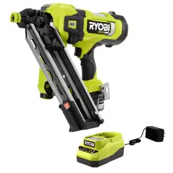
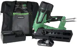
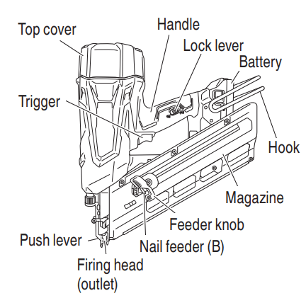
1. Cordless Strip Nailer
2. Battery
3. Battery Charger
SPECIFICATIONS
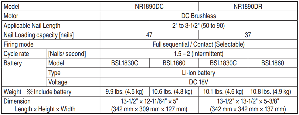
1. Cordless Strip Nailer
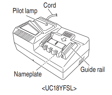
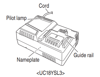
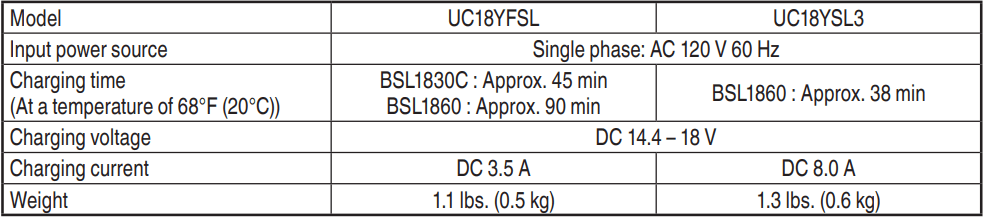
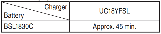
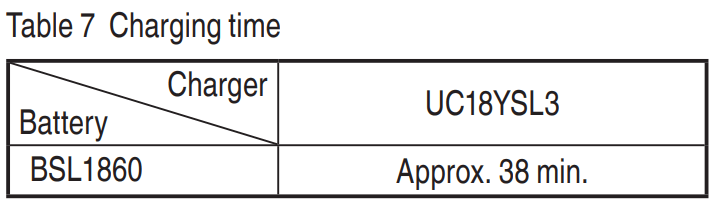
2. Battery Charger
NOTE : The charging time may vary according to temperature and power source voltage.
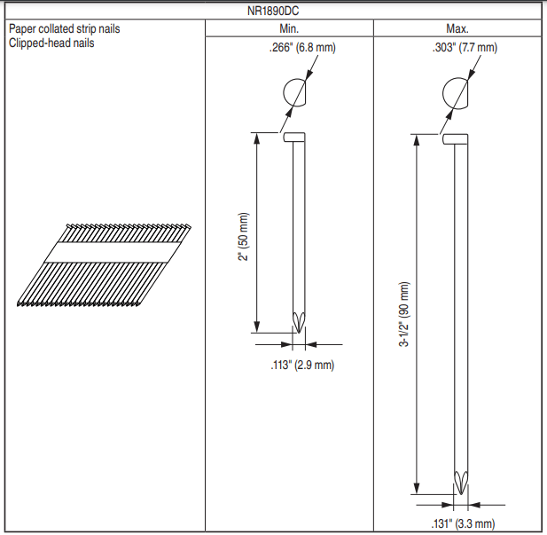
NAIL SELECTION
WARNING : Be sure to use only the genuine HITACHI nails for the NR1890DC or the NR1890DR. The use of any other nails can result in tool malfunction and/or nail breakdown, leading to serious injuries.
Only the nails shown in the Table below can be driven with this Nailer. Dimensions
Dimensions of nails
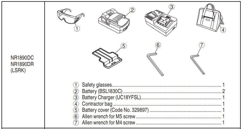
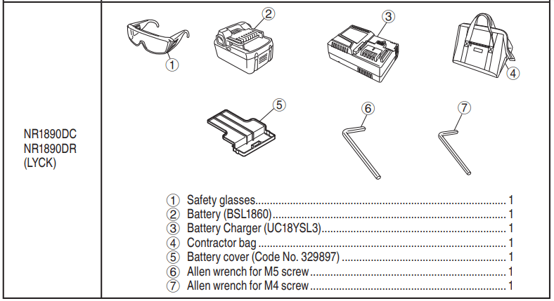
ACCESSORIES
DANGER : Accessories other than those shown below can lead to malfunction and resulting injuries.
STANDARD ACCESSORIES
OPTIONAL ACCESSORIES
sold separately
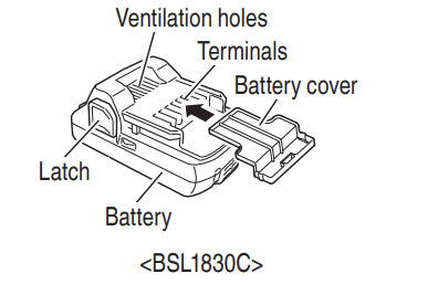
BATTERY (BSL1830C)
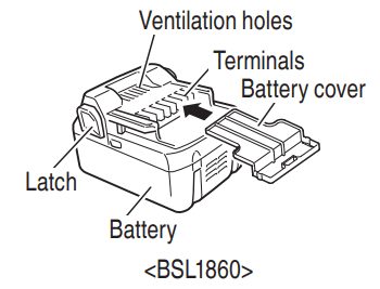
BATTERY (BSL1860)
NOTE : Accessories are subject to change without any obligation on the part of HITACHI.
APPLICATIONS
Floor and wall framing.
Truss build-up, Window build-up.
Subflooring and roof decking.
Wall sheathing.
Mobile home and modular housing construction.
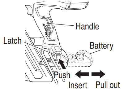
REMOVAL AND INSTALLATION METHOD OF BATTERY
CAUTION : Be sure to keep the fingers away from the trigger and push the lever away from the wood.
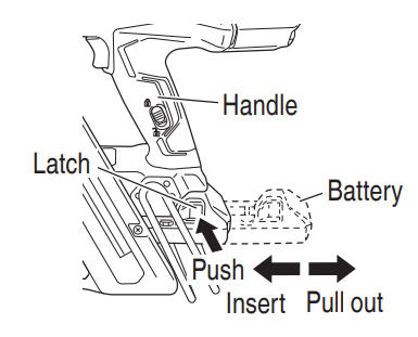
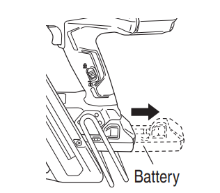
How to install the battery.
Align the battery with the groove in tool handle and slip it into place.
Always insert it all the way until it locks in place with a little click, If not, it may accidentally fall out of the tool, causing injury to you or someone around you.
How to remove the battery.
Withdraw battery from the tool handle while pressing the latch (2 pcs) of the battery
CHARGING METHOD
NOTE : Before plugging into the receptacle, make sure the following points
The power source voltage is stated on the nameplate.
The cord is not damaged.
WARNING : Do not charge at a voltage higher than indicated on the nameplate. If charged at a voltage higher than indicated on the nameplate, the charger will burn up
1. Connect the charger’s power cord to a receptacle. When the power cord is connected, the charger’s pilot lamp will blink in red. (At 1-second intervals)
WARNING : Do not use the electrical cord if damaged. Have it repaired immediately
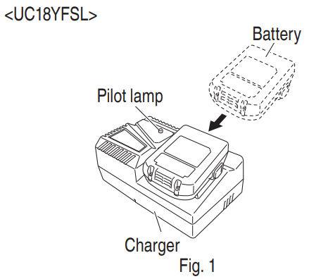
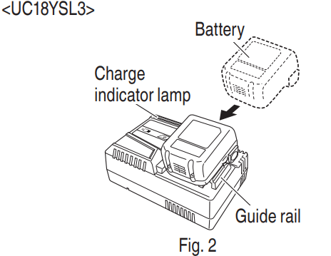
2. Insert the battery to the battery charger. Insert the battery into the battery charger as shown in Fig. 1, 2.
3. Charging
<UC18YFSL>
NOTE: If the pilot lamp flickers in red, pull out the plug from the receptacle and check if the battery is properly mounted.
When the battery is connected to the battery charger, charging will commence and the pilot lamp will light in red. (See Table )
NOTE : If the pilot lamp flickers in red, pull out the plug from the receptacle and check if the battery is properly mounted. When the battery is fully charged, the pilot lamp will blink in red slowly. (At 1-second intervals)
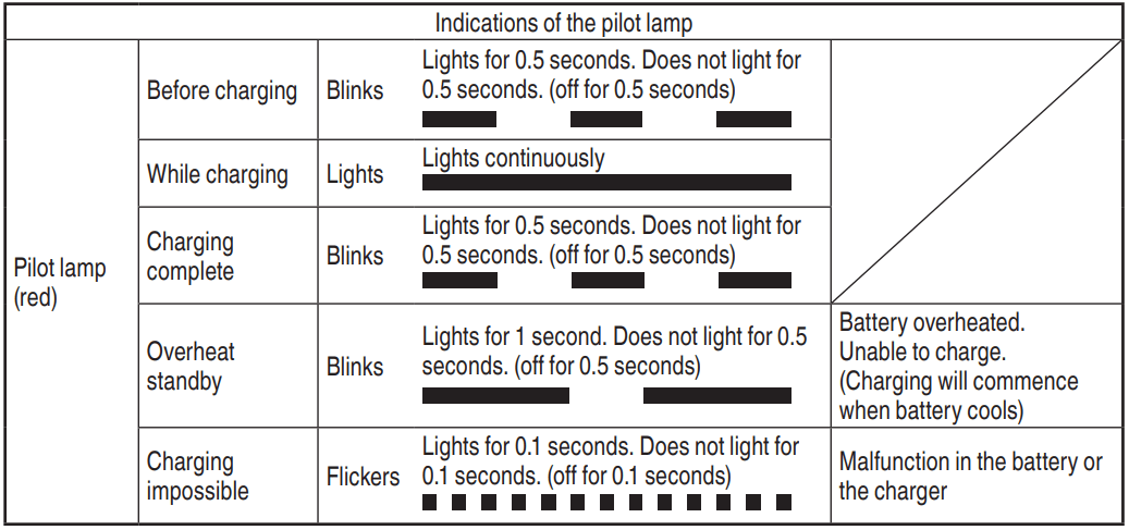
(1) Pilot lamp indication The indications of the pilot lamp will be as shown in Table 2, according to the condition of the charger or the rechargeable battery.
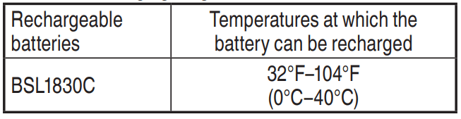
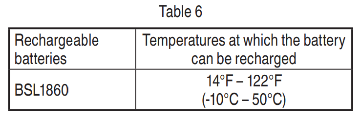
(2) Regarding the temperature of the rechargeable battery. The temperatures for rechargeable batteries are as shown in the Table , and batteries that have become hot should be cooled for a while before being recharged.
(3) Regarding recharging time (At 68°F (20°C))
NOTE: The charging time may vary according to temperature and power source voltage.
<UC18YSL3>
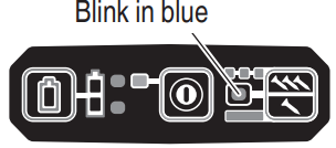
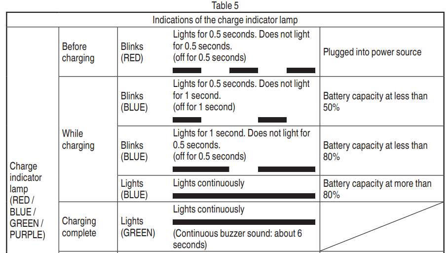
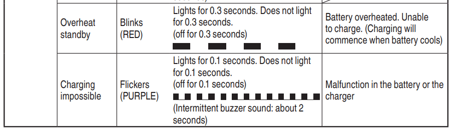
When inserting a battery in the charger, the charge indicator lamp will blink in blue.
When the battery becomes fully recharged, the charge indicator lamp will light up in green.(See Table 5)
(1) Charge indicator lamp indication The indications of the charge indicator lamp will be as shown in Table 5, according to the condition of the battery charger or the battery.
(2) Regarding the temperature of the rechargeable battery. The temperatures for rechargeable batteries are as shown in the Table 6, and batteries that have become hot should be cooled for a while before being recharged.
(3) Regarding recharging time (At 68°F (20°C))
NOTE: The recharging time may vary according to the ambient temperature.
4. Disconnect battery charger from the receptacle.
CAUTION: Do not pull the plug out of the receptacle by pulling on the cord.
Make sure to grasp the plug when removing from receptacle to avoid damaging cord.
5. Remove the battery from the battery charger. Supporting the battery charger with hand, pull out the battery from the battery charger.
NOTE Be sure to pull out the battery from the battery charger after use, and then keep it.
Regarding electric discharge in case of new batteries, etc.
As the internal chemical substance of new batteries and batteries that have not been used for an extended period is not activated, the electric discharge might be low when using them the first and second time. This is a temporary phenomenon, and the normal time required for recharging will be restored by recharging the batteries 2 – 3 times. first
How to make the batteries perform longer
(1) Recharge the batteries before they become completely exhausted. When you feel that the power of the tool becomes weaker, stop using the tool and recharge its battery. If you continue to use the tool and exhaust the electric current, the battery may be damaged and its life will become shorter.
(2) Avoid recharging at high temperatures. A rechargeable battery will be hot immediately after use. If such a battery is recharged immediately after use, its internal chemical substance will deteriorate, and the battery life will be shortened. Leave the battery and recharge it after it has cooled for a while.
CAUTION
● When the battery charger has been continuously used, the battery charger will be heated, thus constituting the cause of the failures. Once the charging has been completed, give 15 minutes rest until the next charging.
● If the battery is charged while it is heated because it has been left for a long time in a location subject to direct sunlight or because the battery has just been used, the pilot lamp of the UC18YFSL charger lights for 1 second, does not light for 0.5 seconds (off for 0.5 seconds) or the charge indicator lamp of UC18YSL3 charger lights for 0.3 seconds, does not light for 0.3 seconds (off for 0.3 seconds). In such a case, first let the battery cool, then start charging.
● When the pilot lamp or charge indicator lamp flickers (at 0.2–second intervals), check for and take out any foreign objects in the charger’s battery installation hole. If there are no foreign objects, it is probable that the battery or charger is malfunctioning. Take it to your authorized Service Center.
HOW TO RECHARGE USB DEVICE
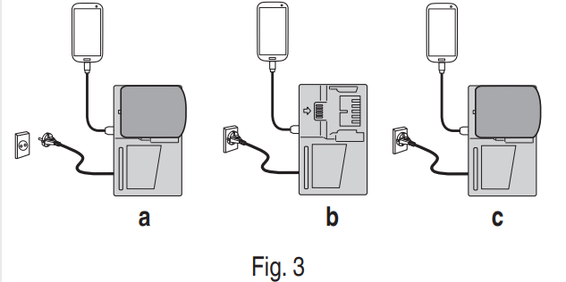
(1) Select a charging method
Depending on the charge method selected, either the battery is inserted into the charger or the power cord is plugged into an outlet.
○ Charging a USB device by battery (Fig. 3-a)
○ Charging a USB device from a electrical outlet (Fig. 3-b)
○ Charging a USB device and battery from a electrical outlet (Fig. 3-c)
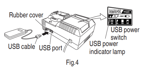
(2) Turn the USB power switch ON (Fig. 4) When you turn the USB power switch ON, the USB power indicator lamp will light up
(3) Connect the USB cable. (Fig. 4) Pull back the rubber cover and firmly plug in a commercially available USB cable (appropriate to the device being charged) into the USB port.
○ When the power cord is not plugged into an outlet and the battery runs out of power, power output will stop and the USB power indicator lamp will shut off .
○ When the USB power indicator lamp goes out, change the battery or plug the power cord into an electrical outlet.
(4) When charging is completed
○ The USB power indicator lamp will not go out when a USB device has been completely charged. To verify charge status, check the USB device.
○ Turn the USB power switch OFF and unplug the power cord from the electrical outlet. (Fig. 4)
○ Remove the battery from the charger and place the rubber cover over the USB port.
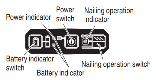
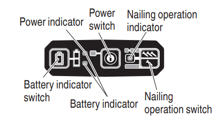
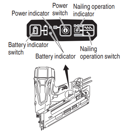
HOW TO OPERATE OPERATION PANEL
(1) Power switch ON Under the condition of “Power switch OFF”, push and hold on Power switch more than 1 second, then power indicator lights in Green.
(2) Power switch OFF Under the condition of “Power switch ON”, push and hold on Power switch more than 1 second, then power indicator goes off .
Under the condition of “Power switch ON”, functions below are active.
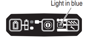
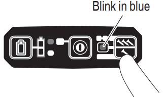
(3) Select Nailing operation mode (Full sequential actuation / Contact actuation) After power switch turn ON, always set in Full sequential actuation mode as initial. (Nailing operation indicator light in blue.)
To change nailing operation mode, push Nailing operation switch once. Every pushing, mode will change between “Full sequential” and “Contact”.
Lighting (Blue):
FULL SEQUENTIAL ACTUATION MECHANISM,
Blinking (Blue):
CONTACT ACTUATION MECHANISM
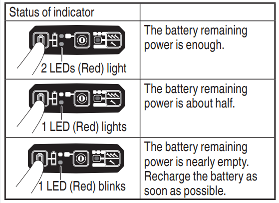
(4) Check Remaining battery level When pressing the battery indicator switch, the battery indicator shows Remaining battery level by status of LED lamp as below.
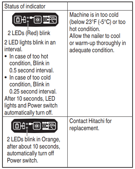
(5) Other functions
In case of operation error, LED lamps show as below.
TESTING THE NAILER
● Operators and others in work area MUST wear safety glasses with side shields that conform to ANSI Z87.1 specifications.
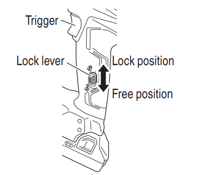
● Make sure the trigger is locked when not firing nails.
This Nailer has a lock mechanism to prevent the nails from being fired.
Set the lock lever at the position to lock the trigger.
Slide the lock lever to the position when the Nailer is to be used, and to the position when it is not in use.
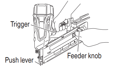
● Never use Nailer unless push lever is operating properly.
The machine employs a preventive mechanism for unloaded operation.
The machine enters a state where the push lever cannot be pushed up. This takes place when the magazine is not loaded with nails or when the remaining number of nails becomes less than 6 or 9
● Use caution not to throw the push lever tip onto wood.
Before actually beginning the nailing work, test the Nailer by using the checklist below. Conduct the tests in the following order. If an abnormal operation occurs, stop using the Nailer and contact a Hitachi authorized service center immediately
(1) REMOVE ALL NAILS AND BATTERIES FROM NAILER.
ALL SCREWS MUST BE TIGHTENED.
THE PUSH LEVER AND TRIGGER MUST MOVE SMOOTHLY with pulling back the feeder knob.
(2) Installing the battery.
Do not operate the push lever or trigger while installing the battery.
(3) Turn on the Power switch.
Turn on the Power switch by pushing and hold on Power switch more than 1 second.
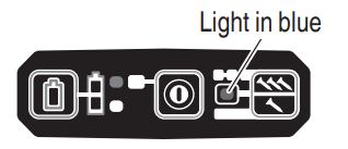
Make sure the power indicator is lit in green, and the nailing operation indicator is lit in blue. (FULL SEQUENTIAL ACTUATION MECHANISM,)
NOTE
● Do not press the push lever and/or pull the trigger during the process of turning the power switch ON. Doing so will prevent the power switch from turning ON.
[Auto power off ]
When the power is turned on but the Nailer is not used for 30 minutes, the Nailer is automatically turned off . To turn on again, press the power switch.
Never leave the Nailer with the power on. This could result in an accident.
Nailing operation indicator
Lighting (Blue):
FULL SEQUENTIAL ACTUATION MECHANISM,
Blinking (Blue):
CONTACT ACTUATION MECHANISM)
Make sure the battery indicator is not blinking. If the battery indicator is blinking in red, the battery doesn’t have enough power and it needs to be charged.
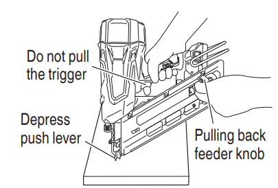
(4) Remove the finger from the trigger and press the push lever against the workpiece with pulling back the feeder knob.
THE NAILER MUST NOT OPERATE.
(5) Separate the push lever from the workpiece. Next, point the nailer downward, with pulling back the feeder knob, pull the trigger and then wait in that position for 5 seconds or longer.
THE NAILER MUST NOT OPERATE
(6)
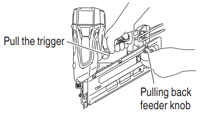
1 Without touching the trigger, depress the push lever against the workpiece with pulling back the feeder knob.
Next, pull the trigger.
THE NAILER MUST OPERATE.
2 Hold the trigger back and depress the push lever against the workpiece again.
THE NAILER MUST NOT OPERATE.
3 Separate the finger from the trigger. Next, 1 is operated again.
THE NAILER MUST OPERATE.
(7) Separate the push lever from the workpiece, pull the trigger.
Depress the push lever against the workpiece within 2 seconds.
THE NAILER MUST NOT OPERATE.
(8) Set the nailing operation indicator blinking ON mode. (CONTACT ACTUATION MECHANISM)
Push the nailing operation switch once, make sure that the indicator is blinking Blue.
Separate the push lever from the workpiece, pull the trigger.
Depress the push lever against the workpiece within 2 seconds.
THE NAILER MUST OPERATE.
(9) If no abnormal operation is observed, you may load nails in the Nailer. Drive nails into the workpiece that is the same type to be used in the actual application.
THE NAILER MUST OPERATE PROPERLY.
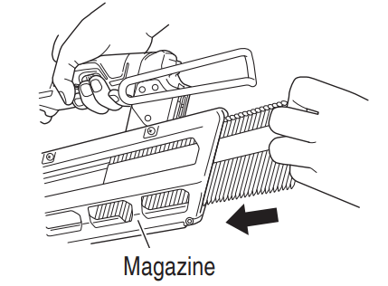
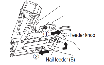
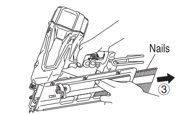
LOADING NAILS
2–Action Nail Feeding!
(1) Insert nail strip into the back of the magazine.
(2) Slide the nail strip forward in the magazine.
(3) Pull the nail feeder (B) back to engage the feeder knob to the nail strip
The Nailer is now ready to operate.
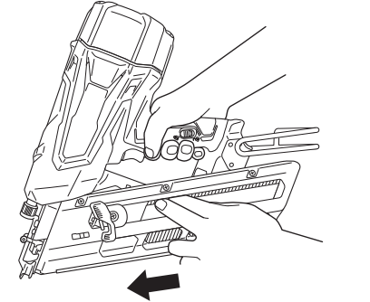
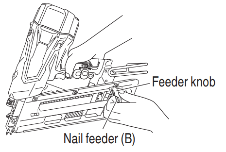
Removing the nails:
1. Pull the feeder knob backward.
2. Return the feeder knob forward quietly while pushing the nail feeder (B).
3. Pull out nails from the back of the magazine.
NAILER OPERATION
This Hitachi nailer is equipped with a nailer operation switching device.
Use FULL SEQUENTIAL ACTUATION MECHANISM or CONTACT ACTUATION MECHANISM in accordance with the work to be performed.
Explanation of the various nailing operations
○ FULL SEQUENTIAL ACTUATION MECHANISM: First, press the push lever against the wood; next, pull the trigger to drive the nail. Follow the same sequence to continue driving nails. After nailing once, nailing will not be possible again until the trigger is released and pressed again.
○ CONTACT ACTUATION MECHANISM: CONTACT ACTUATION can follow two different sequences, depending on your use.
To drive several nails:
1. Pull the trigger.
2. Press the push lever against the wood to drive the nail.
3. If the trigger is held back, a nail will be driven each time the push lever is pressed against the wood.
To drive a single nail:
1. Press the push lever against the wood.
2. Pull the trigger to drive the nail.
3. Remove your finger from the trigger and remove the nailer from the wood.
The machine employs a preventive mechanism for unloaded operation. The machine enters a state where the push lever cannot be pushed up. This takes place when the magazine is not loaded with nails or when the remaining number of nails becomes less than 6 or 9.
METHODS OF OPERATION
This Nailer is equipped with the push lever and does not operate unless the push lever is depressed. There are two methods of operation to drive nails with this Nailer.
They are:
1. Intermittent operation (Trigger fire):
2. Continuous operation (Push lever fire): (1) Intermittent operation (Trigger fire) Use the FULL SEQUENTIAL ACTUATION MECHANISM setting.
● For intermittent operation, Set the nailing operation switch to FULL SEQUENTIAL ACTUATION MECHANISM (Nailing operation indicator is light in blue.) (i.e. Set to SINGLE ACTUATION MECHANISM.)
● To avoid double firing or accidental firing due to recoil.
1) Set to FULL SEQUENTIAL ACTUATION MECHANISM.
2) Pull the trigger rapidly and firmly.
1. Set the nailing operation switch to FULL SEQUENTIAL ACTUATION MECHANISM (Nailing operation indicator is light in blue.) (to set to FULL SEQUENTIAL ACTUATION MECHANISM).(Set the switching device to the nailing operation indicator light in blue mode completely as shown in the diagram. Otherwise, it will be set to CONTACT ACTUATION MECHANISM.
2. Position the nail outlet on the workpiece with finger off the trigger.
3. Depress the push lever firmly until it is completely depressed.
4. Pull the trigger to drive a nail.
5. Remove finger from the trigger and lift the tool off the wood surface completely.
To continue nailing in a separate location, move the nailer along the wood, repeating steps 2 - 5 as required.
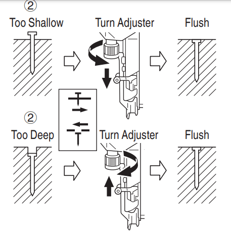
ADJUSTING THE NAILING DEPTH
To assure that each nail penetrates to the same depth, be sure that the Nailer is always held firmly against the workpiece.
If nails are driven too deep or shallow into the workpiece, adjust the nailing in the following order.
1. Remove the battery from the Nailer.
2. If nails are driven too deep, turn the adjuster to the shallow side.
Adjustments are in half-turn increments.
If nails are driven too shallow, turn the adjuster to the deep side.
3. Stop turning the adjuster when a suitable position is reached for a nailing test.
4. Connect the battery to the Nailer. ALWAYS WEAR SAFETY GLASSES. Perform a nailing test.
5. Remove the battery from the Nailer.
6. Choose a suitable position for adjuster.
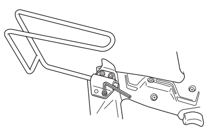
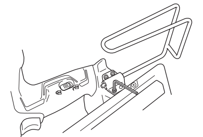
USING THE HOOK
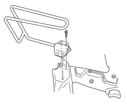
Hook can be installed on the left or right side.
(1) Securely hold the main unit and remove the screw using a screwdriver.
(2) Remove the hook and hook plate
(3) Install the hook on the other side and securely fasten with screw.
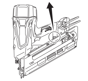
CLEARING A JAM
If nails are jammed in firing head, remove it, and adjust the nailing in the following order.
MAINTENANCE
MAINTENANCE AND INSPECTION
● Remove battery and all remaining fasteners from Nailer when:
1) doing maintenance and inspection; and
2) clearing a jam.
1. Inspecting the magazine
1. Remove battery.
2. Clean the magazine. Remove dust and wood chips which may have accumulated in the magazine.
● Check that the nail feeder slides smoothly by pulling it with finger. If not smooth, nails can be driven at an irregular angle and hurt someone
2. Storing
○ Do not store the Nailer, and battery in a cold weather environment. Keep them in a warm area.
○ When not in use, the Nailer, and battery should be stored in a warm and dry place. Keep it out of reach of children.
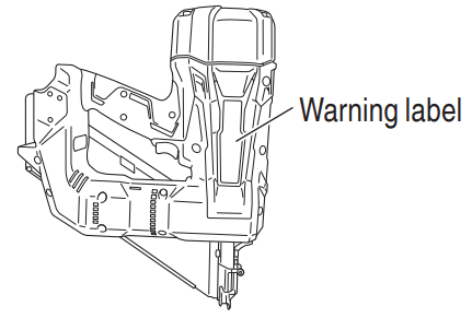
3. WARNING LABEL Change the WARNING LABEL if missing or damaged.
A new WARNING LABEL is available from a Hitachi authorized service center.
4. Maintenance chart (See page 32)
5. Operator troubleshooting (See page 32 – 33)
6. Disposal of the exhausted battery
7. Storage Storing in a place below 104°F (40°C) and out of the reach of children.
8. Service parts list
Maintenance chart
TROUBLESHOOTING
PROBLEM
CHECK METHOD
CORRECTION
Power switch doesn’t turn on. Turn on once, but turn off automatically.
Low battery charge.
Charge the battery.
Damaged internal electronics
Contact Hitachi for replacement.
Push lever and/or trigger is ON state ?
Keep push lever and trigger in OFF state.
Keep no operation over 30 minutes ? (Auto-power off function)
Push and hold power switch more than 1 second to switch “ON”
Nailer doesn’t operate (Power switch ON).
Nailer not enough pressed against workpiece.
Hold nailer firmly and press to the workpiece completely.
Trigger not enough pulled.
Pull the trigger firmly.
More than 2 seconds pass from push lever ON to trigger ON (or trigger ON to push lever ON).
Make sure that less than 2 seconds pass between push lever ON and trigger ON (or between trigger ON and push lever ON).
Preventive mechanism activated. (No nails, or too few fasteners remaining)
Reload the nails into magazine.
Lock lever(Trigger lock function) is “ON” position.
Set Lock lever to “OFF” position. (Refer to page 23 – 24)
Machine is too cold (below 23°F (-5°C)) or too hot.
Allow the nailer to cool or warm-up thoroughly in adequate condition.
Damaged internal electronics.
Contact Hitachi for replacement.
Nailer operates, but no nail is driven.
Magazine is dirty.
Blow and wipe clean the magazine.
Check for a jam
Clear a jam (refer to page 30).
Driver blade worn or damaged?
Contact Hitachi for replacement.
Ribbon spring weakened or damaged?
Replace ribbon spring.
Nail feeder damaged?
Replace nail feeder.
Check for proper nails.
Use only recommended nails
Weak drive. Slow to cycle.
Check position of nailing depth adjustment adjuster.
Readjust according to page 29
Check position of nailing depth adjustment adjuster.
Contact Hitachi for replacement.
Compressed air pressure has become low.
Contact Hitachi for replacement.
Damaged internal electronics.
Contact Hitachi for replacement.
Drives too deep.
Check position of nailing depth adjustment adjuster.
 position to lock the trigger.
 position when the Nailer is to be used, and to the