MultiScanner
®
x85
OneStep
®
Multifunction Scanner
Visit www.ZirconEurope.com for the most current instructions.
EN
1. INSTALLING THE BATTERIES
This tool requires three new AAA (LR03) batteries.
To install or replace the batteries, locate the battery door on the lower backside of the tool.
Press battery door tab in and lift up. Remove old batteries, if needed, and insert three new AAA
batteries, matching the positive (+) and negative (-) terminals according to diagram on tool.
Lower battery door and snap shut.
Upon insertion of batteries, the tool will automatically power on. The blue backlit LCD screen will
illuminate and the MODE icon will power up. The Battery Strength Indicator will appear and the
Signal Strength Indicator bars slowly ramp down during the calibration process. The SpotLite
®
Pointer
will flash and the unit will beep once to indicate the calibration process is complete.
Low Battery Indication: The Battery Strength Indicator icon displays the battery level. When the
battery icon drops down to one bar, the battery level is too low for proper operation of the
MultiScanner
®
x
85. Please replace all three AAA batteries as the tool will not operate correctly
when the battery level is too low. When the battery icon begins to flash, the battery level is not
sufficient to power the tool and the tool’s findings should not be considered accurate. Please replace
all three batteries with a new set immediately.
Battery Saving Mode: Tool will automatically shut off after 3 minutes of non-use.
To manually power off the tool, press and hold the MODE button for approximately 2 seconds.
2. OPERATING TIPS
For optimum scanning results, it is important to properly hold the MultiScanner
®
x
85 and move
slowly when scanning in STUD SCAN, DEEPSCAN_
®
, and AC modes, and scan briskly in Thermal
mode. The following tips will provide more accurate scanning results:
• Grasp the handle with your thumb on one side and your fingers on the other side. Make sure
your fingertips are not touching the surface being scanned or the scanning head of the tool.
• Keep a firm and steady grip on the tool and allow it to calibrate. Moving finger
placement will affect the calibration. Press the MODE button once to recalibrate,
if necessary.
• Hold the tool straight up and down, parallel to the studs, and do not rotate the tool.
• Keep tool flat against the surface and do not rock, tilt, or press hard when slowly sliding
across the surface being scanned.
• Avoid placing your other hand, or any other part of your body, on the surface being scanned.
This will interfere with the tool’s performance.
If you’re receiving erratic scanning results, it may be a result of humidity, moisture within the wall cavity or
drywall, or recently applied paint or wallpaper that hasn’t fully dried. While the moisture may not always be
pvisible, it will interfere with the tool’s sensors. Please allow a few days for the wall to dry out.
WORKING WITH DIFFERENT MATERIALS
Wallpaper: MultiScanner
®
x
85 functions normally on walls covered with wallpaper or fabric, unless the materials
are metallic foil, contain metallic fibers, or are still wet after application.
Wallpaper may need to dry for several
weeks after application.
Freshly painted walls: May take one week or longer to dry after application.
Lath & plaster: Due to irregularities in plaster thickness, it may be difficult for MultiScanner
®
x
85 to locate studs
in STUD SCAN or DEEPSCAN
®
mode. If the plaster has metal mesh reinforcement, MultiScanner
®
x
85 will not be
able to detect through that material.
Extremely textured walls or acoustic ceilings: When scanning a ceiling or wall with an uneven surface,
place thin cardboard on the surface to be scanned and scan over the cardboard.
Wood flooring, subflooring, or gypsum drywall over plywood sheathing: Move the tool slowly. The Signal
Strength Indicator may only display a few bars when the tool locates a stud through thick surfaces.
MultiScanner
®
x
85 cannot scan for wood studs and joists through carpet and padding.
Note: Sensing depth and accuracy can vary due to moisture, content of materials, wall texture, and paint.
Not recommended for use on lath and plaster.
Do not rely exclusively on the detector to locate items behind the scanned surface.
Use other information sources to help locate items before penetrating the surface.
Such additional sources include construction plans, visible points of entry of pipes and wiring into
walls, such as in a basement, and in standard 16 and 24 in. (41 and 61 cm) stud spacing practices.
3. SELECTING THE MODE
Press the MODE button to turn on the tool.
Firmly press the MODE button two times to switch to the desired mode: STUD SCAN or DEEPSCAN
®
for finding wood or metal studs; AC for locating live AC wiring; or THERMAL for locating actively heated
water-filled plastic pipes.
Note: MultiScanner
®
x85 will be in the mode that was last active when the x85 was last shut down, unless the device was shut down in
DEEPSCAN
®
mode. Then, the device will power up in STUD SCAN mode. The unit will start in STUD SCAN when fresh batteries are installed.
4. FINDING A STUD
Always scan for studs with the scanner placed flat against the wall. Press the MODE button two times to
switch between modes until the STUD SCAN icon appears on the top left corner of the LCD display.
Make sure the tool is placed firmly against the wall and press the MODE button one time to calibrate
the tool. During calibration, the Signal Strength Indicator bars will slowly ramp down. Upon completion
of calibration, the SpotLite
®
Pointer and buzzer will momentarily activate. Please wait until the calibration
process is complete before moving the tool. For accurate results, do not remove your hand from the tool
during calibration or at any time the tool is scanning or in use.
Slowly slide tool across surface. As you approach a stud, the relative Signal Strength Indicator will begin
to ramp up. A target at maximum detectable depth will turn on the lowest bar. As the tool approaches the
target, more bars will turn on from bottom to top. It is normal for not all the bars to turn on when a target
has been detected. Only very close, or strong, signals will turn on all the bars. Deep targets may only show
Signal Strength indications and not edges or center.
Continue sliding tool. The Target Indication Bars will indicate the
direction of the approaching stud and the Left/Right arrow will
display when the center of the unit is over the left or right edge of
a stud. A right arrow indicates the left edge of the stud has been
found (A). A left arrow indicates the right edge of the stud has been
found (B). When the center of a stud is located, the Signal Strength
Indicator, Center Indication, and SpotLite
®
Pointer will all illuminate
and the buzzer will sound (C).
In cases of deeper studs (thicker walls), when the center of the stud is located, the Signal Strength Indicator may not ramp as high and only the Center
Indication and SpotLite
®
Pointer will illuminate. If you have difficulty locating a stud after following steps in Section 4, it could be that the stud is deep
(the walls are thick). With the unit still placed flat against the wall and turned on, firmly press the MODE button two times. The stud icon will flash
continuously, indicating that the tool has entered DEEPSCAN
®
mode. Follow steps above again to locate a deep stud. When the center of a deep stud is
located, it is normal for not all the bars to turn on, for the SpotLite
®
Pointer and Center indication not to illuminate, and for the buzzer not to sound.
A target at maximum detectable depth may only turn on the lowest bar. In this case, mark the highest indication to determine the location of the deep stud.
In DeepScan
®
mode, when a target is at its maximum scan depth range, the tool may only indicate the stud edges (and not
the stud center). This will be demonstrated by the CENTER indication and SpotLite® pointer turning on, and remaining on,
throughout the entire width of the stud.
*Wood studs may only detect to 1
1
⁄2 in. (38 mm) deep.
Please note: Very dense materials, such as metal studs, can look much wider at depths of 1-1
1
⁄2 in. (25-38 mm) or less.
ACT
™
(Auto Correcting Technology)—During scanning, the tool will recalibrate itself if it starts over a stud.
This recalibration is transparent and no indication is made.
5. SCANNING IN AC MODE
Electrical field locators may not detect live AC wires if wires are more than 2 in. (50 mm) from
the scanned surface, encased in conduit, present behind a plywood shear wall or metallic wall
covering, or if moisture is present in the environment or scanned surface.
DO NOT ASSUME THERE ARE NO LIVE ELECTRICAL WIRES IN THE WALL. DO NOT TAKE ACTIONS
THAT COULD BE DANGEROUS IF THE WALL CONTAINS A LIVE ELECTRICAL WIRE. ALWAYS TURN
OFF THE ELECTRICAL POWER, GAS, AND WATER SUPPLIES BEFORE PENETRATING A SURFACE. FAILURE TO FOLLOW
THESE INSTRUCTIONS MAY RESULT IN ELECTRIC SHOCK, FIRE, AND/OR SERIOUS INJURY OR PROPERTY DAMAGE.
Always turn off power when working near electrical wires.
Note: AC Scan will only detect live (hot) unshielded AC wiring.
To switch to AC mode, firmly press the MODE button two times until the AC icon appears on the left side of the LCD display (A).
Make sure the tool is placed firmly against the wall and press the MODE button one time to calibrate the tool. During calibration,
the Signal Strength Indicator bars will slowly ramp down. Upon completion of calibration, the SpotLite
®
Pointer and buzzer will
momentarily activate. Please wait until the calibration process is complete before moving the tool. Slowly slide tool across surface.
As you approach an AC field, the relative Signal Strength Indicator bars will start to ramp up (B). A target at maximum detectable
depth may only turn on the lowest bar. As the tool approaches the target, more bars will turn on from bottom to top. It is normal
for not all the bars to turn on when a target has been detected.
Only very close, or strong, signals will turn on all the bars. Mark the location where you get the highest AC indication (the most
bars on the Signal Strength Indicator). If it is a strong target, the Signal Strength Indicator, Center Indication, and SpotLite
®
Pointer
will all illuminate and the buzzer will sound (C). (The Center icon indicates the AC field peak.)
If you calibrate the unit and begin scanning over an area:
• …with AC present and move to an area with less AC, the unit will recalibrate automatically. The calibration is complete
when the beeper beeps once.
• …that has a detectable level of AC present and the AC field is constant throughout the area, there may not be enough
differentiation in the voltage for the Signal Strength Indicator bars to increase/decrease or to locate the wire.
However, to indicate the presence of a baseline, or constant, AC field, the Target Indication Bars at the bottom of the
LCD screen will turn on and move outwards from the center repeatedly (Figures 1-3), meaning the wall likely contains
hot electrical wires.
• …with a very large AC signal present, one that saturates the measurement capability of the unit, the device will indicate
this by flashing the Signal Strength Indicator bars, turning on the SpotLite
®
beam, and sounding the buzzer.
If at any time during your scan you suspect electrical wires, but do not detect any, move the tool from the surface and recalibrate the
unit in the air. Place the tool back on the wall and begin your scan again (without hitting the MODE button again). This will activate
the tool’s maximum sensitivity.
6. SCANNING IN THERMAL MODE
Firmly press the MODE button two times to switch between modes until the Thermal icon appears on the top right corner of the
LCD display. Make sure the tool is placed firmly against the surface and press the MODE button one time to calibrate the tool.
During calibration, the Signal Strength Indicator bars will slowly ramp down. Upon completion of calibration, the SpotLite
®
Pointer
and buzzer will momentarily activate. Please wait until the calibration process is complete before moving the tool (A). This process
may take up to 15 seconds when the unit is first powered up. It will calibrate in 2-3 seconds after the initial turn on. Slide tool across
surface in a steady, brisk (approx. 12 in. or 30 cm per second) manner.
Note: Scanning too slow will result in no indication of targets.
The relative Signal Strength Indicator bars will appear when it senses a maximum temperature relative to the environment, indicating
the center of a warm target (B). A target at maximum detectable depth may only turn on the lowest bar. When the tool passes over the
target, more bars may turn on. It is normal for not all the bars to turn on when a target has been detected. Only very close, or strong,
signals will turn on all the bars. Sweep through the location several times so the tool can calibrate to the surface.
Mark the location where you get the highest thermal indication (the most bars on the Signal Strength Indicator). If it is a strong target,
the Signal Strength Indicator, Center Indication, and SpotLite
®
Pointer will all illuminate and the buzzer will sound (C).
This MultiScanner
®
x
85 OneStep
®
wall scanner features four (4)
scanning modes:
• STUD SCAN: Locates the center, edges, and direction of wood
and metal studs up to 1 in. (25 mm) deep
• DEEPSCAN
®
: Locates the center, edges, and direction of wood
and metal studs up to 2 in. (50 mm) deep*
• AC: Detects and locates live unshielded AC wires up to 2 in.
(50 mm) deep
• THERMAL: Thermally detects the center of actively heated
water-filled
1
⁄2
in. (13 mm) diameter plastic pipes up to 2 in.
(50 mm) deep
WARNING
Detects other objects besides studs in
STUD SCAN/DEEPSCAN
®
mode.
Finds more targets than there should be.
• Electrical wiring and metal/plastic pipes may be near or
touching back surface of wall.
• In STUD SCAN mode or AC mode, the unit is lifted off the wall
during scanning or the user’s hand is not continuously on the
unit during the entire test.
• Scan the area in AC mode to determine if hot AC is present.
• Check for other studs equally spaced to either side 12, 16, or 24 in. (31, 41, or 61 cm) apart or for the same stud at several
places directly above or below the first scan area.
• Do not lift unit off the wall and and keep hand continuously on unit during the entire scanning time.
Situation Probable Cause Solution
You suspect electrical wires, but do not
detect any.
In Thermal mode, constant Center Indication
or no indication at all.
Unit behaves erratically or provides
inconsistent results.
• Changes in temperature very minimal.
• Speed of scanning may not be at its optimal pace.
• Low battery.
• Turn up radiant heating setting so changes in temperature are more recognizable.
• Speed of scanning must be at a brisk, continuous pace (approx. 12 in. or 30 cm per second) in this particular mode; scanning
at a very slow and deliberate speed is too slow and and scanning at a faster pace is not optional.
• Do not place any body part, such as hands, elbows, arms, or feet on the test surface or close to the test area. Shoes must be
worn when scanning flooring. A handprint can be detected for up to 20 seconds or longer after the hand has been removed.
• Replace with all three brand new AAA (LR03) batteries.
• Wires may not be live.
• Wires are close to metal door frame or shielded by metal
conduit, a braided wire layer, or metallic wall covering.
• Wires deeper than 2 in. (50 mm) from surface might not
be detected.
• Turn on switches to outlets.
• Plug a lamp into outlet and turn on switch.
* Note: MultiScanner
®
x85 cannot scan for wires close to metal door frame, shielded by metal conduit or layer,
or located deeper than 2 in. (50 mm). Verify these conditions before scanning.
Constant readings of studs near windows
and doors.
Area of voltage appears much larger than
actual wire (AC only).
• Double and triple studs are usually found around doors
and windows. Solid headers are above them.
• Voltage detection can spread on drywall as much as 12 in.
(30 cm) laterally from each side of an actual electrical wire.
• Calibrate farther away from the window or door so you can accurately detect the studs.
• To narrow detection, recalibrate the x85 within the area where the AC field peak or highest AC indication was first observed
and scan again.
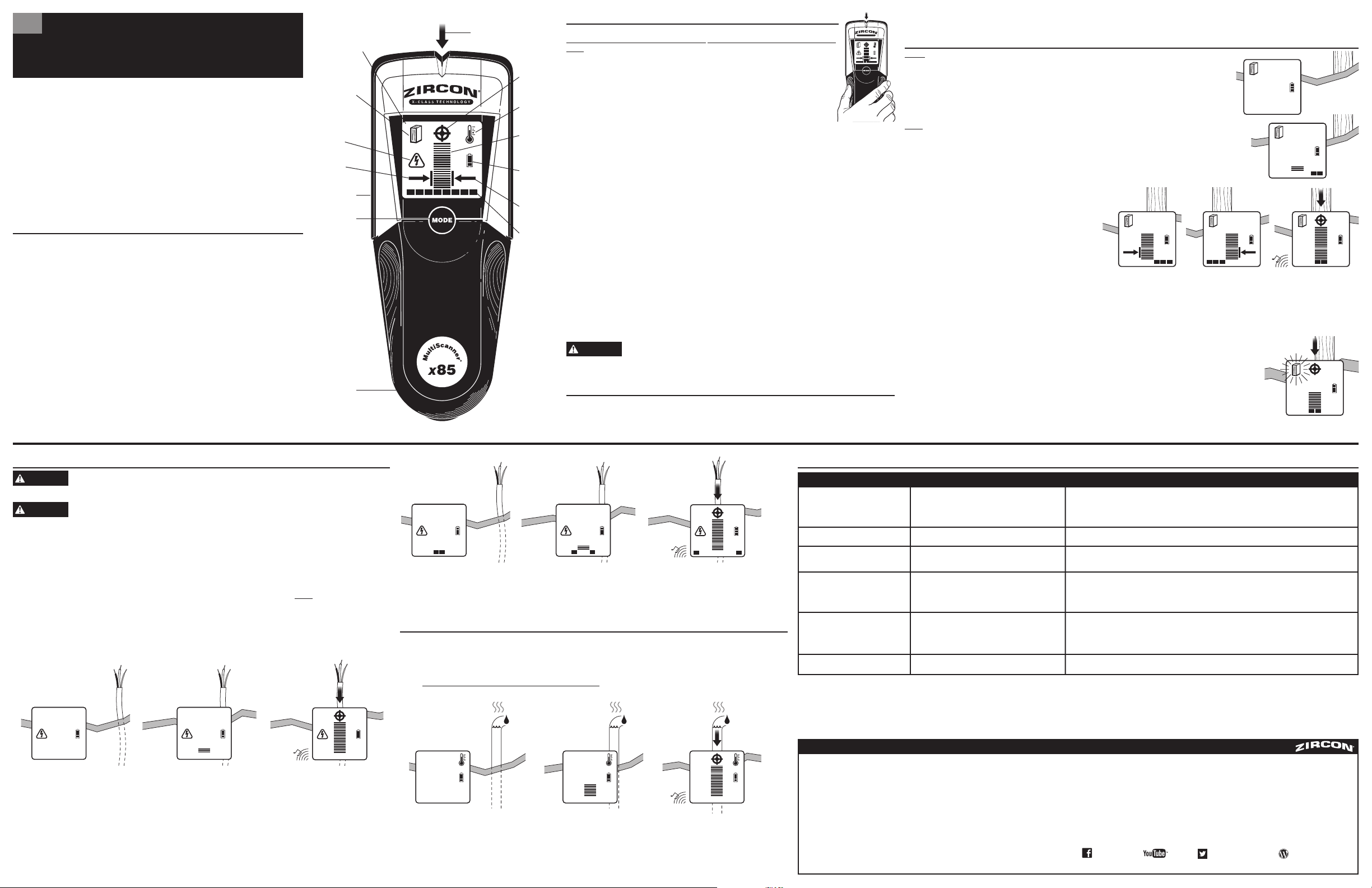
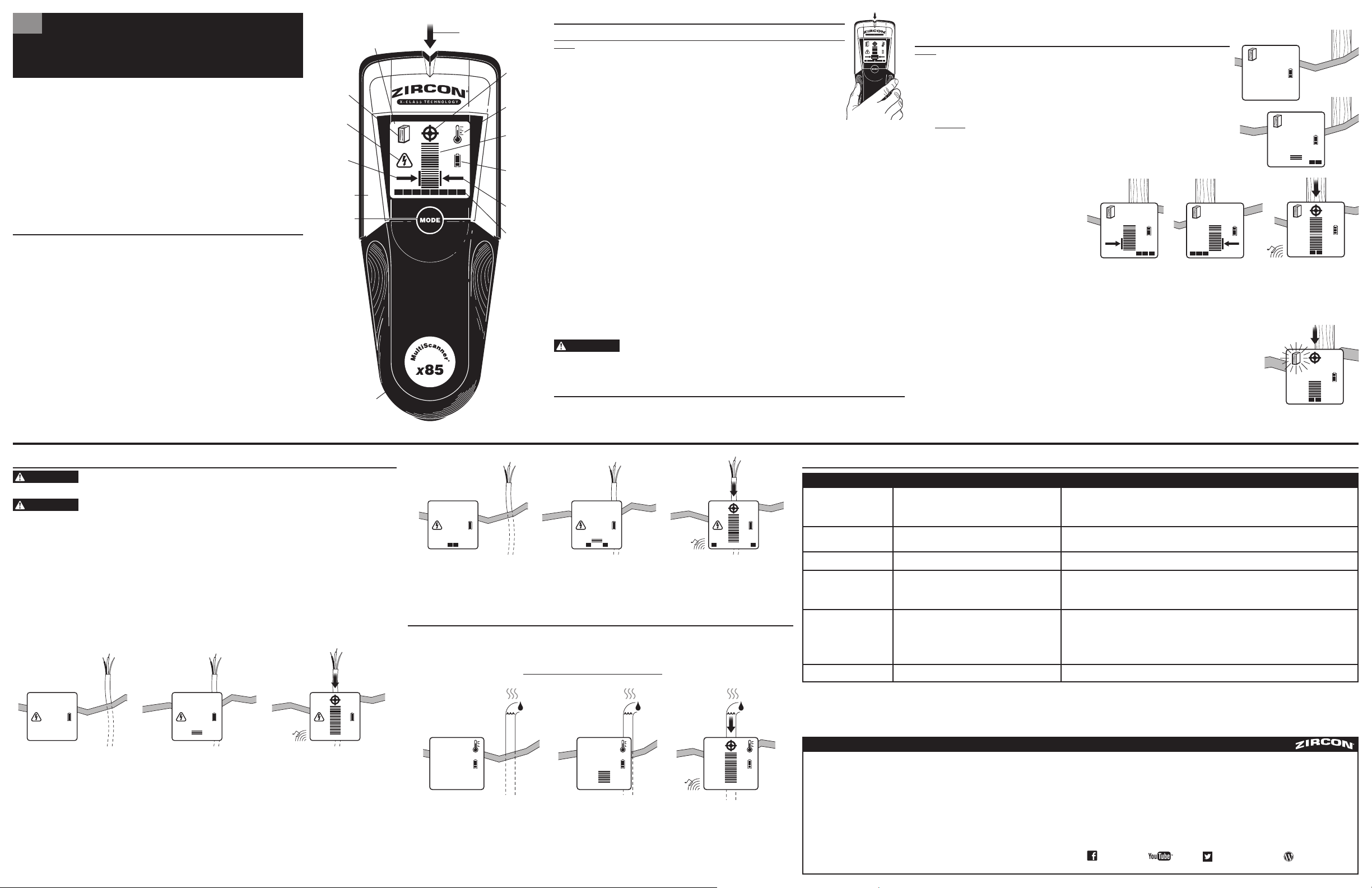
SpotLite
®
Pointer
Backlit LCD
AC Mode
Left Edge
Indicator
STUD SCAN
Mode (solid
stud icon) /
DEEPSCAN
®
Mode (flashing
stud icon)
Thermal Sensor
(back of unit)
Mode Button
Battery Door
(back of unit)
Center
Indication
Thermal
Mode
Signal
Strength
Indicator
Battery
Strength
Indicator
Right Edge
Indicator
Target
Indication
Bars
WARNING
WARNING
A
B C
A B C
1 2 3
A B C
7. HELPFUL HINTS (See also Section 2, OPERATING TIPS)
*Wood studs may only detect to
1
1
⁄2 in. (38 mm)
deep.
LIMITED 1 YEAR WARRANTY
Zircon Corporation, (“Zircon”) warrants this product to be free from defects in materials and workmanship for two years
from the date of purchase. Any in-warranty defective product returned to Zircon*, freight prepaid with proof of purchase
date and $5.00 to cover postage and handling, will be repaired or replaced at Zircon’s option. This warranty is limited to
the electronic circuitry and original case of the product and specifically excludes damage caused by abuse, unreasonable
use or neglect. This warranty is in lieu of all other warranties, express or implied, and no other representations or
claims of any nature shall bind or obligate Zircon. Any implied warranties applicable to this product are limited to the
one year period following its purchase. IN NO EVENT WILL ZIRCON BE LIABLE FOR ANY SPECIAL, INCIDENTAL OR
CONSEQUENTIAL DAMAGES RESULTING FROM POSSESSION, USE OR MALFUNCTION OF THIS PRODUCT.
In accordance with government regulations, you are advised that: (i) some states do not allow limitations on how
long an implied warranty lasts and/or the exclusion or limitation of incidental or consequential damages, so the above
limitations and/or exclusions may not apply to you, and further (ii) this warranty gives you specific legal rights and you
may also have other rights which vary from state to state.
Return product freight prepaid with proof of purchase date (dated sales receipt) and $5.00 to cover postage
and handling, to:
Zircon Corporation
*Attn: Returns Department
1580 Dell Avenue
Campbell, CA 95008-6918 USA
Be sure to include your name and return address. Out of warranty service and repair, where proof of purchase
is not provided, shall be returned with repairs charged C.O.D. Allow 4 to 6 weeks for delivery.
Customer Service, 1-800-245-9265 or 1-408-963-4550
Monday–Friday, 8:00 a.m. to 5:00 p.m. PST
www.zircon.com • [email protected]
© 2016 Zircon Corporation • P/N 65765 • Rev E 05/16
Visit www.zircon.com/support for the most current instructions.
ACT, DeepScan, MultiScanner, OneStep, SpotLite, and Zircon are registered trademarks or trademarks of Zircon Corporation.
FCC Part 15 Class B Registration Warning
This device complies with Part 15 of FCC Rules. Operations subject to the following two conditions: (1) this device
may not cause harmful interference, and (2) this device must accept any interference received, including interference
that may cause undesired operation.
ZirconCorporation ZirconTV
ZirconTools
|
ZirconToolPro
ZirconTools
MultiScanner
®
x85
OneStep
®
Escáner de Pared Multifunción
1. INSTALACIÓN DE BATERÍAS
Este instrumento opera con 3 baterías AAA (LR03) nuevas.
Para colocar o cambiar las baterías, ubique la tapa del compartimiento de las baterías en la parte inferior
y posterior del instrumento. Presione la pestaña de la tapa del compartimiento de las baterías y levante
hacia arriba. Retire las baterías usadas, si fuese necesario, e inserte tres baterías AAA nuevas, haciendo
corresponder los terminales positivo (+) y negativo (-) de acuerdo con el diagrama del instrumento.
Baje la tapa del compartimiento de las baterías y ciérrela a presión.
Al insertar las baterías, la herramienta encenderá automáticamente, la pantalla LCD se iluminará con
una luz de fondo azul y el icono MODE se activará. El Indicador de Potencia de Batería aparecerá y las
barras Indicadoras de Potencia de Señal irán disminuyendo lentamente durante el proceso de calibración.
El Puntero SpotLite
®
destellará y la unidad emitirá un sonido una vez para indicar que el proceso de
calibración ha finalizado.
Indicación de batería con poca carga: El icono Indicador de potencia de la batería muestra el nivel de
carga. Cuando el icono de la batería desciende a una barra, el nivel de la batería está demasiado bajo
para que el MultiScanner
®
x85 pueda funcionar adecuadamente. Cambie las tres baterías AAA, ya que el
instrumento no funcionará adecuadamente cuando el nivel de la batería esté demasiado bajo. Cuando el
icono de la batería comience a destellar, el nivel de la batería no es suficiente para alimentar el instrumento
y las lecturas no deben considerarse precisas. Cambie las tres baterías por un nuevo juego de inmediato.
Modalidad de ahorro de batería: El instrumento se apaga automáticamente 3 minutos después de no
estar en uso.
Para apagar la unidad manualmente, oprima y sujete el botón MODE por aproximadamente 2 segundos.
2. CONSEJOS DE OPERACIÓN
Para resultados óptimos de escaneo, es importante sujetar correctamente el MultiScanner
®
x85 y moverlo
lentamente cuando se escanea en STUD SCAN, DEEPSCAN
®
_ , y modo AC, y escanee rápidamente en el modo
Térmico. Los siguientes consejos prácticos le brindarán resultados de escaneo más precisos:
• Sujete el asidero con el pulgar en un lado y los dedos en el otro lado. Compruebe que sus dedos no estén
tocando la superficie que va a escanear o el cabezal escaneador del instrumento.
• Mantenga la unidad en la mano firmemente y estable y deje que se calibre, ya que cualquier cambio en
colocación de los dedos afectará la calibración. Presione el botón MODE una vez para recalibrar,
si necesario.
• Mantenga el instrumento recto mientras se deslice hacia arriba y hacia abajo, paralelo a las vigas,
y no gire el instrumento.
• Mantenga el instrumento plano contra la superficie y no lo gire, incline ni presione demasiado cuando
lo deslice lentamente por la superficie que está escaneando.
• Evite colocar la otra mano o cualquier otra parte de su cuerpo en la superficie que está escaneando.
Esto interferirá con el desempeño del instrumento.
Si recibe resultados de escaneo erráticos, puede ser el resultado de humedad dentro de la cavidad de la pared o del panel de yeso,
o pintura o papel tapiz aplicado recientemente que no haya secado completamente. Aunque la humedad no siempre esté visible,
interferirá con los sensores del instrumento. Deje transcurrir algunos días para que la pared seque completamente.
TRABAJANDO CON DIFERENTES MATERIALES
Papel tapiz: MultiScanner
®
x85 funciona normalmente en paredes cubiertas con papel tapiz o tela, a menos que los materiales
sean de lámina metálica, contengan fibras metálicas o estén aún húmedos después de su aplicación.
Es posible que el papel tapiz
tarde varias semanas para secarse después de ser aplicado.
Paredes recientemente pintadas: Es posible que tarde una semana o más para que sequen después de la aplicación de la
pintura.
Emplaste de yeso y madera: Emplaste de yeso y madera: Debido a las irregularidades en el espesor del emplaste,
puede que el MultiScanner
®
x85 tenga dificultad de encontrar vigas en los modos STUD SCAN y DEEPSCAN
®
. Si el
emplaste contiene un refuerzo de malla metálica, el MultiScanner
®
x85 no podrá detectar a través de ese material.
Paredes extremadamente texturizadas o techos acústicos: Cuando escanee un techo o una pared con una superficie
irregular, coloque un cartón delgado en la superficie que va a escanear y hágalo sobre el cartón.
Revestimiento de pisos de madera, contrapisos o paneles de yeso sobre revestimiento de contrachapado:
Mueva el instrumento lentamente. Es posible que el Indicador de potencia de señal sólo pueda mostrar algunas barras
cuando el instrumento ubica una viga a través de superficies gruesas.
MultiScanner
®
x85 no puede escanear vigas o vigas de madera a través de alfombras y material acolchado.
Nota: La detección de profundidad y la precisión pueden variar debido a la humedad, el contenido de los materiales, la textura
de la pared y la pintura. No se recomienda para uso en listones y yeso.
No confíe exclusivamente en el detector para ubicar elementos detrás de la superficie
escaneada. Haga uso de otras fuentes de información para ayudarle a ubicar los
elementos antes de penetrar la superficie. Tales fuentes adicionales podrían ser los planos de construcción,
los puntos de entrada visibles de tubos y cableado en las paredes, tales como en un sótano y las prácticas
de separación de vigas de 16 y 24 pulg. (41 y 61 cm).
3. SELECCIÓN DE MODO
Presione el botón MODE para activar el instrumento.
Presione firmemente dos veces el botón de MODO para cambiar al modo deseado: STUD SCAN o DEEPSCAN
®
(modo de vigas)
para encontrar vigas de madera o metal; AC (modo CA) para localizar alambres vivos de AC; o THERMAL (modo térmico) para
localizar tuberías de plástico llenas de agua calentada activamente.
Nota: El MultiScanner
®
x85 estará en el modo que se encontraba activo la última vez que se apagó, a menos que éste se haya apagado en el modo DEEPSCAN
®
.
Entonces el dispositivo encenderá en el modo STUD SCAN. La unidad encenderá en el modo STUD SCAN cuando se instalen baterías nuevas.
4. CÓMO ENCONTRAR UNA VIGA
Siempre escanee en busca de vigas con el escáner en posición plana contra la pared. Presione el botón MODE dos
veces para cambiar entre modos hasta que el icono STUD SCAN aparezca en la esquina superior izquierda de la
pantalla LCD. Compruebe que el instrumento esté colocado firmemente contra la pared y presione el botón MODE
una vez para calibrar el instrumento. Durante la calibración, Las barras Indicadoras de Potencia de Señal irán
disminuyendo lentamente. Por favor espere hasta que el proceso de calibración haya terminado antes de mover
la herramienta. Al terminar la calibración, el Puntero SpotLite
®
y el sonido se activarán momentáneamente.
Para resultados precisos, no quite la mano de la herramienta durante la calibración o cuando la herramienta esté
escaneando o en uso.
Deslice lentamente el instrumento por la superficie. A medida que se aproxima a una viga, el Indicador de potencia
relativa de la señal comenzará a ascender. Un objetivo a la profundidad máxima detectable activará la barra más baja.
A medida que el instrumento se aproxima al objetivo, aparecerán más barras de abajo hacia arriba. Es normal que no
aparezcan todas las barras cuando se haya detectado un objetivo. Sólo las señales muy cercanas o fuertes activarán
todas las barras. Objetivos a cierta profundidad podrían sólo mostrar las barras del Indicador de Potencia de Señal,
y no los bordes o el centro.
Continúe deslizando el instrumento. Las Barras Indicadoras
de Objetivo indicarán la dirección de la viga a la cual se
aproxima y la flecha izquierda/derecha aparecerá cuando
el centro de la unidad esté sobre el borde izquierdo o
derecho de una viga. Una flecha a la izquierda indica que
ha encontrado el borde derecho de la viga (B). Cuando se
ha ubicado el centro de una viga, el Indicador de potencia
de la señal, la indicación del centro y el Puntero SpotLite
®
se iluminarán y el tono sonará (C).
En caso de paredes gruesas, cuando se localice la viga, puede que el Indicador de Potencia de Señal no suba tan alto y que sólo se iluminen la Indicación
de Centro y el Puntero SpotLite
®
. Si tiene dificultad localizando una viga después de seguir los pasos en esta sección, puede ser que la viga sea profunda
(las paredes sean gruesas). Con la unidad estando en posición contra la pared y encendida, presione firmemente el botón MODE dos veces. El icono de viga
parpadeará continuamente, indicando que la herramienta ha entrado en el modo de escaneado profundo DEEPSCAN
®
. Siga de nuevo los pasos arriba para localizar
una viga profunda. Cuando se encuentra el centro de una viga con mayor profundidad, es normal que no se enciendan todas las barras, que el puntero SpotLite
®
y
el indicador del Centro no se iluminen, y que el timbre no suene. El objetivo a la profundidad máxima detectable sólo puede encender la barra inferior. En este caso,
marque la indicación más alta para determinar la ubicación de la viga con mayor profundidad.
En el modo DeepScan
®
, cuando un objetivo esté en su máximo rango de profundidad de escanéo puede que la herramienta sólo
indique los bordes (y no el centro de la viga). Esto sera demostrado cuando se enciendan el indicador de CENTRO e indicador
SpotLite
®
, permaneciendo encendido, a través de todo el ancho de la viga.
*Las vigas de madera pueden ser detectables sólo hasta
1
1
⁄2
pulg. (38 mm)
de profundidad.
Tome en cuenta: Los materiales densos, como las vigas metálicas, pueden aparecer más anchas que realmente son a profundidades
de 1-1
1
⁄2 pulg. (25-38 mm) o menos.
ACT
™
(Tecnología de autocorrección)—Durante el escaneo, el instrumento se recalibrará a sí mismo si comienza sobre una
viga. Esta recalibración es transparente y no se produce ninguna indicación.
5. ESCANEO EN MODO AC (CA)
Es posible que los localizadores de campos eléctricos no detecten cables vivos de CA si estos están a más
de 2 pulg. (50 mm) de la superficie escaneada, se encuentran entubados, ubicados detrás de una pared
lámina de contrachapado o un revestimiento metálico de pared, o si hay humedad en el ambiente o en la superficie escaneada.
NO SUPONGA QUE NO HAY CABLES ELÉCTRICOS VIVOS EN LA PARED. NO TOME ACCIONES QUE
PODRÍAN SER PELIGROSAS SI LA PARED CONTIENE UN CABLE ELÉCTRICO VIVO. SIEMPRE CORTE EL
SUMINISTRO ELÉCTRICO, DE GAS Y AGUA ANTES DE PENETRAR UNA PARED. EL INCUMPLIMIENTO DE ESTAS INSTRUCCIONES
PODRÍA OCASIONAR UNA DESCARGA ELÉCTRICA, UN INCENDIO Y/O LESIONES GRAVES O DAÑO A LA PROPIEDAD.
Siempre corte el suministro eléctrico cuando trabaje cerca de cables eléctricos.
Nota: Las modalidad AC (CA) sólo detectará cableado vivo (activo) de CA de sin revestimiento.
Para cambiar al modo AC, presione firmemente el botón MODE dos veces hasta que el icono AC aparezca en el lado izquierdo de la pantalla
LCD (A). Compruebe que el instrumento esté colocado firmemente contra la pared y presione el botón MODE una vez para calibrar el instru-
mento. El icono AC destellará temporalmente. Al terminar la calibración, el Puntero SpotLite
®
y el sonido se activarán momentáneamente.
Espere hasta que el proceso de calibración haya finalizado antes de mover el instrumento. Deslice lentamente el instrumento por la superficie.
Cuando la unidad se aproxime a un campo eléctrico de CA, las barras indicadores mostrarán actividad (B). Una localización a la máxima
profundidad podría sólo encender la barra más baja. Cuando la unidad se aproxime al campo, las barras iluminarán de abajo a arriba.
Es normal que todas las barras iluminen cuando un campo de CA haya sido detectado.
Sólo las señales muy cercanas, o fuertes, activarán todas las barras. Marque la ubicación donde obtenga la indicación CA más alta (la mayoría
de las barras del Indicador de potencia de la señal). Si es un objetivo fuerte, el Indicador de potencia de la señal, la indicación del centro y el
Puntero SpotLite
®
se iluminarán y el tono sonará (C). (El icono central indica el punto máximo del campo de CA.)
Si usted calibra la unidad e inicia el escaneo sobre un área:
• …cuando haya CA presente y mueva la unidad a un área con menos CA, la unidad se recalibrará automáticamente. La calibración se
completa cuando el se oye el tono una vez.
• …que tiene un nivel detectable de CA presente y el campo de CA es constante a través de toda el área, es posible que no exista
suficiente diferencia de voltaje para que las barras Indicadoras de nivel de intensidad incrementen o reduzcan o para localizar
el alambre. Sin embargo, para indicar la presencia de base o un campo eléctrico constante de CA, las Barras Indicadoras de Objetivo
en la base de la pantalla LCD se encenderán y moverán desde el centro hacia fuera repetidamente (Figuras 1–3), advirtiendo de la
posibilidad de que existan cables eléctricos vivos (activos).
7. SUGERENCIAS ÚTILES (Consulte también el Sección 2 - CONSEJOS PRÁCTICOS PARA ESCANEAR)
El MultiScanner
®
x
85 OneStep
®
escáner de pared posee cuatro (4) modos
de escaneo:
• STUD SCAN: Localiza el centro, bordes y dirección de vigas de madera
y metal hasta 1 pulg. (25 mm.) de profundidad
• DEEPSCAN
®
: Localiza el centro, bordes y dirección de vigas de madera
y metal hasta 2 pulg. (50 mm.) de profundidad
• AC (CA = Corriente Alterna): Detecta y localiza cables vivos de CA sin
revestimiento a una profundidad de hasta 2 pulg. (50 mm)
• THERMAL (TÉRMICA): Detecta térmicamente el centro de tubos
plásticos (Ø
1
⁄2 pulg. [13 mm]) de agua caliente a una profundidad
de hasta 2 pulg. (50 mm)
• …con una señal fuerte de CA presente, la unidad indicará saturación de la capacidad de medición mediante las barras destalladas del
Indicador de Potencia de Señal, el Puntero SpotLite
®
encendido, y la emisión del sonido.
Si en algún momento durante el escaneo sospecha de la existencia de cables eléctricos, pero no detecta ninguno, aleje la unidad de la
superficie y recalíbrela en el aire. Coloque la unidad en la superficie y escanee de nuevo (sin oprimir el botón MODE de nuevo). Esto activará
la máxima sensibilidad del aparato.
6. CÓMO ESCANEAR EN LA MODALIDAD THERMAL (TÉRMICA)
Presione el botón MODE dos veces para alternar entre modalidades hasta que el icono THERMAL aparezca en el extremo superior derecho
de la pantalla LCD. Compruebe que el instrumento esté colocado firmemente contra la superficie y presione el botón MODE una vez para
calibrar el instrumento. El icono THERMAL destellará temporalmente. Al terminar la calibración, el Puntero SpotLite
®
y el sonido se activarán
momentáneamente. Espere hasta que el proceso de calibración haya finalizado antes de mover el instrumento. Este proceso puede tardar hasta
15 segundos cuando la unidad se encienda por la primera vez. Calibrará en 2-3 segundos después del encendido inicial. Deslice la herramienta
a través de la superficie con una velocidad constante de (aprox. 12 pulg. ó 30 cm por segundo).
Nota: Deslizar la unidad o escanear demasiado despacio resultará en no indicación de objetivos.
Las barras Indicadoras de Potencia de Señal relativa aparecerán cuando detecte una temperatura máyor con respecto al medio ambiente,
indicando el centro del objetivo caliente (B). Un objetivo a la profundidad máxima detectable puede que active sólo la barra más baja.
Cuando la herramienta pase sobre el objetivo, más barras podrán encenderse. Es normal que no aparezcan todas las barras cuando se haya
detectado un objetivo. Sólo las señales muy cercanas o fuertes activarán todas las barras. Escanee la zona varias veces para que el instrumento
pueda calibrarse a la superficie.
Marque la ubicación donde obtenga la indicación térmica más alta (la mayoría de las barras del Indicador de potencia de la señal). Si es un
objetivo fuerte, el Indicador de potencia de la señal, la indicación del centro y el Puntero SpotLite
®
se iluminarán y el tono sonará.
ES
A B C
A B C
1 2 3
A B C
Puntero SpotLite
®
Iluminación de
fondo LCD
Modalidad de
AC (CA)
Indicador de
borde izquierdo
Modo STUD SCAN
(icono de viga
sólido) / Modo
DEEPSCAN
®
(icono de viga
intermitente)
Sensor térmico
(parte posterior
de la unidad)
Botón MODE
(MODALIDAD)
Tapa del compartimiento
de baterías (parte posterior
del instrumento)
Indicador
de centro
Modalidad
Thermal
(térmica)
Indicador de
potencia de
la señal
Indicador de
potencia de
la batería
Indicador de
borde derecho
Barras
Indicadoras
de Objetivo
ADVERTENCIA
ADVERTENCIA
GARANTÍA LIMITADA DE 1 AÑO
La Empresa Zircon, (“Zircon”) garantiza que este producto se encuentra libre de defectos en sus materiales y mano de obra
por un período de un año a partir de la fecha de su compra. Cualquier producto defectuoso en garantía devuelto a Zircon*,
con flete prepago con comprobante de la fecha de compra y $5.00 para cubrir el envío, será reparado y reemplazado a
discreción de Zircon. Esta garantía está limitada al circuito electrónico y a la caja original del producto y excluye
específicamente daños causados por abuso, uso indebido o negligencia. Esta garantía reemplaza cualquier otra garantía,
expresa o implícita
y Zircon no será responsable por ninguna otra afirmación o reclamo de cualquier naturaleza. Toda garantía implícita que se
aplique a este producto está limitada a un período de un año a partir de la fecha de su compra. EN NINGÚN CASO ZIRCON
SERÁ RESPONSABLE POR CUALQUIER DAÑO ESPECIAL, SECUNDARIO O COMO CONSECUENCIA DE LA TENENCIA, EL USO O
EL MAL FUNCIONAMIENTO DE ESTE PRODUCTO.
De acuerdo con las reglamentaciones gubernamentales, se le notifica que: (i) algunos estados no permiten limitaciones
en cuanto al período de duración de una garantía implícita y/o a la exclusión o a la limitación de daños secundarios o
consecuentes, de modo que las limitaciones y/o exclusiones mencionadas anteriormente pueden no ser aplicables en su caso
y además (ii) esta garantía le otorga derechos legales específicos, y usted también podría tener otros derechos que pueden
variar de estado en estado.
Envíe el producto con flete prepago con el comprobante con la fecha de compra (recibo de ventas con fecha) y $5.00 para
gastos de envío a:
Zircon Corporation
*Attn: Returns Department (Departamento de Devoluciones)
1580 Dell Avenue
Campbell, CA 95008-6918 USA
Asegúrese de incluir su nombre y dirección para la devolución. El servicio y la reparación fuera de la garantía, cuando no se
provea el comprobante de compra, se devolverá reparado y el pago será contra entrega. Deje transcurrir de 4 a 6 semanas
para el envío.
Atención al Cliente, 1-800-245-9265 o 1-408-963-4550
Lunes a Viernes, 8:00 a.m. a 5:00 p.m. Hora estándar del Pacífico
www.zircon.com • [email protected]
© 2016 Zircon Corporation • P/N 65765 • Rev E 05/16
ACT, DeepScan, MultiScanner, OneStep, SpotLite, y Zircon son marcas comerciales registradas o marcas comerciales de Zircon Corporation.
Detecta otros objetos además de las
vigas en la modalidad STUD (viga).
Encuentra más objetivos de los que
deben haber.
• El cableado eléctrico y los tubos de metal/plástico pueden estar
cerca o en contacto con la superficie posterior de la pared.
• En el modo STUD SCAN o en el modo AC, la unidad se ha
levantado de la pared durante el escaneo, o la mano del usuario no
está puesto continuamente en la unidad durante toda la prueba.
• Escanee el área en la modalidad AC (CA) para determinar si hay cables de CA vivos presentes.
• Revise otras vigas a igual separación en ambos lados a 12, 16, ó 24 pulg. (31, 41, ó 61 cm) o en la misma viga en varios
lugares directamente por encima o por debajo de la primera área escaneada.
• No levante la unidad de la pared y mantenga la mano continuamente en la unidad durante todo el tiempo de escaneo.
Situación Causa Probable Solución
Usted sospecha que hay cables
eléctricos, pero no detecta ninguno.
En la modalidad THERMAL (térmica),
hay indicación constante de centro o
ninguna indicación.
La unidad se comporta erráticamente
o brinda resultados inconsistentes.
• Los cambios en temperatura son mínimos.
• La velocidad de escaneo puede que no esté a su ritmo óptimo.
• Batería con poca carga.
• Encienda la calefacción radiante para que los cambios de temperatura se puedan reconocer.
• La velocidad de escaneo deberá ser con rapidez, a un ritmo continuo (aprox. 12 pulg. ó 30 cm por segundo) en este modo en
particular; escanear a una velocidad muy lenta y premeditada es demasiado lento y escanear a un ritmo más rápido de la dicha
velocidad no es óptimo.
• No ponga ninguna parte del cuerpo, como manos, codos, brazos o pies/rodillas en la superficie de prueba o cerca del área de
prueba.Deberá de usar zapatos cuando se escanee el piso (no descalzo). Una huella de mano puede ser detectada hasta por
20 segundos después de que la mano se haya quitado de la superficie.
• Reemplace las tres baterías AAA (LR03) por otras nuevas.
• Es posible que los cables no estén vivos.
• Los cables están cerca de marcos de puertas metálicas o protegidos
por tubo de metal, forro con capas metálicas o una cubierta metálica.
• Es posible que no detecte los cables que se encuentren a
una profundidad mayor de 2 pulg. (50 mm) de la superficie.
• Active los interruptores de los tomacorrientes.
• Enchufe una lámpara en un tomacorriente y encienda el interruptor.
Nota: El MultiScanner
®
x85 no puede escanear cables cerca de marcos de puerta metálicos, protegidos por tubo o capas
metálicas o localizados a una profundidad mayor de 2 pulg. (50 mm). Verifique estas condiciones antes de escanear.
Lecturas constantes de vigas cerca de
puertas o ventanas.
El área de voltaje aparece mucho
mayor que el cable real (sólo CA).
• Generalmente se encuentran vigas dobles o triples en
las inmediaciones de puertas y ventanas. Sobre ellos se
encuentran vigas sólidas.
• La detección del voltaje puede abarcar el panel de yeso hasta 12 pulg.
(30 cm) de forma lateral desde cada lado de un cable eléctrico real.
• Calibre lejos de ventanas y puertas para que pueda detectar las vigas con precisión.
• Para estrechar la zona de detección, recalibre el x85 en el área donde el campo de AC o la lectura de AC más alta fué
observada y escanee de nuevo.
*Las vigas de madera pueden ser detectable sólo hasta
1
1
⁄2
pulg. (
38 mm)
de profundidad.
Advertencia de la inscripción en la clase B de la FCC Parte 15
Este dispositivo cumple con la Parte 15 de las Reglas FCC. El funcionamiento está sujeto a las siguientes dos
condiciones: (1) este dispositivo no debe ocasionar interferencia nociva, y (2) este dispositivo debe aceptar
cualquier interferencia que reciba, incluyendo interferencia que pueda ocasionar el funcionamiento no deseado.
Visite www.zircon.com/support para actualización de las instrucciones.
ADVERTENCIA
ZirconCorporation ZirconTV
ZirconTools
|
ZirconToolPro
ZirconTools
7. CONSEILS UTILES (Reportez-vous également au numéro 2, Conseils d´utilisation)
1. INSTALLATION DES PILES
Cet outil requiert trois piles AAA (LR03) neuves.
Pour installer ou remplacer les piles, trouvez la porte du compartiment des piles à l´arrière de l´outil.
Appuyez sur l´onglet de la porte du compartiment des piles, puis soulevez-la. Retirez les piles usées,
le cas échéant, et insérez trois piles AAA neuves en faisant correspondre les bornes positives (+)
et négatives (–) des piles à celles indiquées sur l´outil. Abaissez la porte du compartiment des piles,
puis appuyez sur celle-ci pour la fermer.
L´outil se mettra automatiquement en marche lorsque les piles sont insérées. L´écran (ACL)
rétroéclairé bleu sera illuminé et l´icône MODE sera affichée. L´indicateur de l´état des piles
apparaîtra et l´indicateur de l´intensité du signal diminuera lentement pendant le processus
d´étalonnage. Le Pointeur SpotLite
™
clignotera et l´outil émettra un signal sonore pour indiquer
que le processus d´étalonnage est terminé.
Indication de pile faible : L´icône indique l´état des piles. Lorsque l´icône des piles affiche une
seule barre, les piles sont trop faibles pour le fonctionnement adéquat de l´outil MultiScanner
™
x
85. Veuillez remplacer les trois piles AAA par trois piles neuves, car l´outil ne fonctionnera pas
correctement lorsque les piles sont trop faibles. Lorsque l´icône des piles commence à clignoter, les
piles sont trop faibles pour mettre l´outil en marche et les lectures ne devraient pas être considérées
comme étant exactes. Veuillez remplacer immédiatement les trois piles par des piles neuves.
Mode d´économie des piles : L´outil s´éteindra automatiquement s´il n´est pas utilisé pendant
trois minutes.
Pour éteindre manuellement l´outil, appuyez sur le bouton MODE et maintenez-le enfoncé pendant
environ 2 secondes.
2. CONSEILS D´UTILISATION
Pour obtenir les meilleurs résultats, il est important de tenir correctement l´outil MultiScanner
™
x
85,
de le déplacer lentement lors de la détection en modes DÉTECTION DE MONTANTS, DEEPSCAN
™
——
et
DÉTECTION DU C.A. et de le déplacer plus rapidement en mode Thermique. Les conseils suivants vous
aideront à obtenir des lectures plus précises :
• Placez votre pouce d´un côté de la poignée et vos doigts de l´autre côté. Assurez-vous que vos doigts
ne touchent pas à la surface à balayer ni à la tête de lecture de l´outil.
• Tenez fermement l´outil et attendez que l´étalonnage soit terminé; si vous changez la position
de votre prise, cela aura un effet sur l´étalonnage. Appuyez une fois sur le bouton MODE pour
reprendre l´étalonnage, au besoin.
• Tenez l´outil bien à la verticale, parallèlement aux montants, et ne le tournez pas.
• Tenez l´outil contre la surface à balayer; ne l´inclinez pas et n´appuyez pas trop fort en le déplaçant sur la surface
à balayer.
• Évitez de placer votre autre main, ou toute autre partie de votre corps, sur la surface à balayer. Ceci nuira au rendement
de l´outil.
Si vous obtenez des résultats inconstants lors du balayage, cela pourrait être causé par de l´humidité dans la cavité du mur
ou de la peinture ou du papier peint qui ne sont pas entièrement secs. Bien que l´humidité ne soit pas toujours visible, elle
nuira au fonctionnement des capteurs de ´outil. Veuillez attendre quelques jours afin que le mur soit entièrement sec.
TRAVAILLER AVEC DIFFÉRENTS MATÉRIAUX
Papier peint : L´outil MultiScanner
™
x
85 fonctionne normalement sur les murs recouverts de papier peint ou de tissu, sauf
si les matériaux sont des feuilles métalliques, s´ils contiennent des fibres métalliques ou s´ils ne sont pas entièrement secs.
Le papier peint pourrait nécessiter plusieurs semaines pour être entièrement sec.
Murs fraîchement peints : Ils pourraient nécessiter une semaine ou plus avant d´être entièrement secs.
Plâtre sur lattis : En raison des irrégularités dans l´épaisseur du plâtre, il peut être difficile pour l´outil MultiScanner
™
x
85
de trouver les montants en mode DÉTECTION DE MONTANTS ou en mode DEEPSCAN
™
. Si le plâtre est renforcé par un
grillage métallique, l´outil MultiScanner
™
x
85 ne réussira pas à effectuer la détection au travers de ce matériau.
Murs hautement texturés et plafonds en carreaux insonorisants : Dans le cas d´un plafond ou d´un mur ayant une
surface irrégulière, placez un carton mince sur la surface et effectuez le balayage sur le carton.
Parquet, sous-plancher ou panneau de gypse sur un revêtement en contreplaqué : Déplacer lentement l´outil.
L´indicateur de l´intensité du signal pourrait n´afficher que quelques barres lorsque l´outil trouve un montant au travers
d´une surface épaisse.
L´outil MultiScanner
™
x
85 ne peut pas détecter les montants ou les poutrelles à travers les moquettes et les sous-tapis.
Remarque : La profondeur et la précision de détection peuvent varier en raison de l´humidité, de la composition du
matériau, de la texture du mur et de la peinture. Non recommandé pour l´utilisation sur les murs en plâtre sur lattis.
Ne vous fiez pas uniquement au détecteur pour déceler les éléments situés sous
la surface balayée. Utilisez d´autres sources de renseignements pour vous aider à
les localiser avant de percer la surface. Les autres sources de renseignements peuvent comprendre les dessins
d´exécution et les points d´entrée visibles des tuyaux et du câblage dans les murs, comme dans un sous-sol ou
dans l´espacement standard de 41 ou 61 cm (16 ou 24 po) entre les montants.
3. SÉLECTION DU MODE
Appuyez sur le bouton MODE pour mettre l´outil en marche.
Appuyez fermement deux fois sur le bouton MODE pour passer au mode souhaité : DÉTECTION DE MONTANTS ou DEEPSCAN
™
pour trouver les montants en bois ou en métal; C.A.
pour trouver les fils électriques sous tension; THERMIQUE pour localiser les tuyaux en plastique de chauffage actif remplis d´eau.
Remarque : L´outil MultiScanner
™
x85 sera réglé au dernier mode utilisé avant la mise hors tension, sauf dans le cas du mode DEEPSCAN
™
. Dans ce cas, l´outil sera en mode
DÉTECTION DE MONTANTS lors de la mise en marche. L´outil sera réglé au mode DÉTECTION DE MONTANTS lorsque des piles neuves sont installées.
4. LOCALISER UN MONTANT
Placez toujours l´outil bien à plat sur le mur lors du balayage visant à trouver les montants. Appuyez deux fois sur le bouton
MODE pour passer d´un mode à un autre, continuez jusqu´à ce que l´icône DÉTECTION DE MONTANTS soit affichée dans le coin
supérieur gauche de l´écran ACL. Assurez-vous que l´outil est placé fermement sur le mur, puis appuyez sur le bouton MODE une fois
pour effectuer l´étalonnage. Pendant l´étalonnage de l´outil, les barres de l´indicateur de l´intensité du signal diminueront lentement.
Lorsque l´étalonnage est terminé, le Pointeur SpotLite
™
et le signal sonore seront activés momentanément. Veuillez attendre la fin
du processus d´étalonnage avant de déplacer l´outil. Pour obtenir des résultats précis, n´enlevez pas votre main de l´outil pendant
l´étalonnage, la détection ou le fonctionnement de l´outil.
Glissez lentement l´outil sur la surface. Lorsque l´outil s´approche d´un montant, l´indicateur de l´intensité relative du signal commencera à
augmenter. Lorsque la cible se trouve à la profondeur maximale, la barre la plus inférieure sera affichée. Lorsque l´outil s´approche de la cible,
d´autres barres seront affichées, du bas vers le haut. Il est normal que les barres ne soient pas toutes affichées lorsqu’une cible est détectée.
Les barres seront toutes affichées seulement lorsque la cible est très près de la surface ou très forte. Lorsque les cibles sont profondes, il est
possible que seule l´intensité du signal soit indiquée et non les arêtes ou le centre.
Continuez à glisser l´outil sur la surface. Les barres d´indication de la cible signaleront
le sens du prochain montant et la flèche gauche ou droite sera affichée lorsque le
centre de l´outil se trouve sur l´arête gauche ou droite du montant. Une flèche vers
la droite indique que l´arête gauche du montant a été trouvée (A). Une flèche vers la
gauche indique que l´arête droite du montant a été trouvée (B). Lorsque le centre du
montant est localisé, l´indicateur de ´intensité du signal, l´indicateur du centre et le
Pointeur SpotLite
™
seront illuminés et le signal sonore sera entendu (C).
Dans le cas de montants plus profonds (murs plus épais), lorsque le centre du montant est localisé, l´indicateur de l´intensité du signal pourrait ne pas afficher autant de barres et
seuls l´indicateur du centre et le Pointeur SpotLite
™
seront lumineux. Si vous éprouvez de la difficulté à localiser un montant après avoir suivi les étapes de la section 4, cela pourrait
être causé par un montant profond (les murs sont épais). Gardez l´outil contre le mur et en marche, puis appuyez fermement deux fois sur le bouton MODE. L´icône de DÉTECTION
DE MONTANTS clignotera sans interruption, indiquant que l´outil a passé au mode DEEPSCAN
™
. Suivez de nouveau les étapes ci-dessus pour trouver un montant profond. Lorsque
le centre d´un montant profond est localisé, il est normal que les barres ne soient pas toutes affichées, que le pointeur SpotLite
™
et l´indication du centre ne soient pas illuminés et
que le signal sonore ne soit pas entendu. Lorsque la cible se trouve à la profondeur maximale détectable, il est possible que seule la barre la plus inférieure soit affichée. Dans ce cas,
marquez l´indication la plus forte afin de déterminer l´emplacement du montant profond.
En mode DeepScan
™
, lorsque la cible est située à la profondeur maximale de détection, l´outil pourrait indiquer seulement les arêtes des montants
(et non le centre des montants). Ceci sera démontré par l´affichage continu de l´indicateur du CENTRE et l´illumination continue du pointeur SpotLite
™
pendant le balayage du montant en entier.
*Les montants en bois pourraient seulement être détectés à 38 mm (1,5 po) de profondeur ou moins.
Veuillez noter : Les matériaux très denses, comme les montants en métal, peuvent paraître beaucoup plus larges à une profondeur de
25 à 38 mm (de 1 à 1,5 po) ou moins.
ACT
™
(Technologie de correction automatique)— Pendant le balayage, l´outil procédera à un étalonnage s´il est placé sur un montant au
début de son utilisation. Cet étalonnage est transparent et il n´est pas indiqué.
5. LA DÉTECTION EN MODE C.A.
Les détecteurs de courant électrique peuvent parfois ne pas déceler les fils c.a. sous tension
s´ils sont situés à plus de 50 mm (2 po) de la surface balayée, s´ils se trouvent dans un conduit,
dans un mur de contreventement en contreplaqué ou derrière un revêtement mural métallique ou en présence d´humidité
dans l´environnement et la surface balayée.
NE PRÉSUMEZ PAS L´ABSENCE DE FILS ÉLECTRIQUES SOUS TENSION DANS LE MUR. N´EFFECTUEZ
PAS DE TRAVAUX QUI POURRAIENT ÊTRE DANGEREUX SI UN FIL ÉLECTRIQUE SOUS TENSION ÉTAIT
PRÉSENT DANS LE MUR. DÉSACTIVEZ TOUJOURS LES SOURCES D´ALIMENTATION EN ÉLECTRICITÉ, GAZ ET EAU AVANT DE PERCER
UNE SURFACE. LE DÉFAUT DE SE CONFORMER À CES DIRECTIVES PEUT CAUSER UNE DÉCHARGE ÉLECTRIQUE, UN INCENDIE AINSI
QUE DES BLESSURES GRAVES ET DES DOMMAGES MATÉRIELS.
Coupez toujours l´alimentation électrique lorsque vous travaillez à proximité de fils électriques.
Remarque : Le balayage c.a. ne détectera que les câbles électriques c.a. non blindés sous tension (chargé).
Pour passer au mode C.A., appuyez fermement deux fois sur le bouton MODE jusqu´à ce que l´icône C.A. soit affichée sur le côté gauche
de l´écran ACL (A). Assurez-vous que l´outil est placé fermement sur le mur, puis appuyez sur le bouton MODE une fois pour effectuer
l´étalonnage. Pendant l´étalonnage de l´outil, les barres de l´indicateur de l´intensité du signal diminueront lentement. Lorsque l´étalonnage
est terminé, le Pointeur SpotLite
™
et le signal sonore seront activés momentanément. Veuillez attendre la fin du processus d´étalonnage
avant de déplacer l´outil. Glissez lentement l´outil sur la surface.
Lorsque l´outil s´approche d´un champ électrique c.a., les barres de l´indicateur de l´intensité relative du signal commenceront à augmenter
(B). Lorsque la cible se trouve à la profondeur maximale détectable, il est possible que seule la barre la plus inférieure soit affichée. Lorsque
l´outil s´approche de la cible, d´autres barres seront affichées, du bas vers le haut. Il est normal que les barres ne soient pas toutes affichées
lorsqu´une cible est détectée.
Les barres seront toutes affichées seulement lorsque la cible est très près de la surface ou que le signal est fort. Marquez l´emplacement
pour lequel vous avez la plus forte indication de c.a. (le plus grand nombre de barres de l´indicateur d´intensité du signal). Si la cible est forte,
l´indicateur de l´intensité du signal, l´indicateur du centre et le Pointeur SpotLite
™
seront illuminés et le signal sonore sera entendu (C).
(L´icône du centre indique l´intensité maximale du champ électrique c.a.)
Si vous étalonnez l´outil et commencez à balayer une surface :
• …dans laquelle se trouve un courant alternatif (c.a.) et que vous déplacez l´outil à un endroit où le courant est moindre, l´outil sera
automatiquement étalonné de nouveau. Le processus d´étalonnage est terminé lorsque le signal sonore est entendu une fois.
• …dans laquelle se trouve un niveau détectable de courant alternatif (c.a.) et un champ électrique uniforme à tous les endroits, il est
possible que la variation de tension ne soit pas suffisante pour faire augmenter/diminuer les barres de l´indicateur de l´intensité du signal
ou pour localiser le fil électrique. Cependant, afin de signaler la présence d´ une base de référence ou d´un champ électrique uniforme,
les barres d´indication de la cible, situées dans la partie inférieure de l´écran ACL, clignoteront et se déplaceront continuellement vers
l´extérieur à partir du centre (Figures 1–3), pour indiquer que le mur contient probablement des fils électriques sous tension.
• …dans laquelle se trouve un très grand signal électrique (c.a.) qui sature la capacité de mesure de l´outil, cela sera indiqué par le
clignotement des barres de l´indicateur de l’intensité du signal et par l´activation du faisceau SpotLite
™
et du signal sonore.
Si, en tout temps pendant le balayage, vous soupçonnez la présence de fil électrique, mais que l´outil ne les détecte pas, éloignez l´outil de la
surface et étalonnez-le de nouveau dans l´air. Replacez l´outil sur le mur et recommencez le balayage de la surface (sans appuyer de nouveau
sur le bouton MODE). Ceci activera la sensibilité maximale de l´outil.
6. DÉTECTION EN MODE THERMIQUE
Appuyez deux fois sur le bouton MODE pour passer d´un mode à un autre, continuez jusqu´à ce que l´icône THERMIQUE soit affichée dans le
coin supérieur droit de l´écran ACL. Assurez-vous que l´outil est placé fermement sur la surface, puis appuyez sur le bouton MODE une fois
pour effectuer l´étalonnage. L´icône du mode Thermique clignotera temporairement. Lorsque l´étalonnage est terminé, le Pointeur SpotLite
™
et
le signal sonore seront activés momentanément. Veuillez attendre la fin du processus d´étalonnage avant de déplacer l´outil (A). Ce processus
peut prendre jusqu´à 15 secondes après la mise en marche initiale de l´outil. Les étalonnages subséquents prendront de 2-3 secondes. Glissez
l´outil sur la surface d´une manière uniforme et rapide (environ 30 cm (12 po) par seconde).
Remarque : Un balayage trop lent entraînera l´absence d´indication de cibles.
Les barres de l´indicateur d´intensité relative du signal apparaissent lorsqu´une température maximale relativement à l´environnement est
détectée, indiquant le centre d´une cible chaude (B). Lorsque la cible se trouve à la profondeur maximale détectable, il est possible que seule
la barre la plus inférieure soit affichée. Lorsque l´outil glisse sur la cible, d´autres barres peuvent être affichées. Lorsque l´outil s´approche
de la cible, d´autres barres seront affichées, du bas vers le haut. Il est normal que les barres ne soient pas toutes affichées lorsqu’une cible
est détectée. Les barres seront toutes affichées seulement lorsque la cible est très près de la surface ou très forte. Balayez plusieurs fois
l´emplacement afin de permettre à l´outil de s´étalonner selon la surface.
Marquez l´emplacement pour lequel vous avez la plus forte indication thermique (le plus grand nombre de barres de l´indicateur d´intensité
du signal). Si la cible est forte, l´indicateur de l´intensité du signal, l´indicateur du centre et le Pointeur SpotLite
™
seront illuminés et le signal
sonore sera entendu.
A B C
1 2 3
A B C
MultiScanner
™
x85
OneStep
™
Détecteur multifonctions
FR
Le MultiScanner
™
x85 OneStep
™
est doté de quatre modes de détection :
•
DÉTECTION DE MONTANTS : Pour trouver le centre, les arêtes et le sens des
montants en bois ou en métal jusqu´à une profondeur de 25 mm (1 po).
•
DEEPSCAN
™
: Pour trouver le centre, les arêtes et le sens des montants en
bois ou en métal jusqu´à une profondeur de 50 mm (2 po)*
•
C.A. : Pour détecter et trouver les câbles c.a. non blindés sous tension
jusqu´à 50 mm (2 po) de profondeur
•
THERMIQUE : Pour la détection thermique du centre des tuyaux en
plastique de 13 mm (
1
⁄2 po) de diamètre de chauffage actif remplis d´eau
jusqu´à 50 mm (2 po) de profondeur
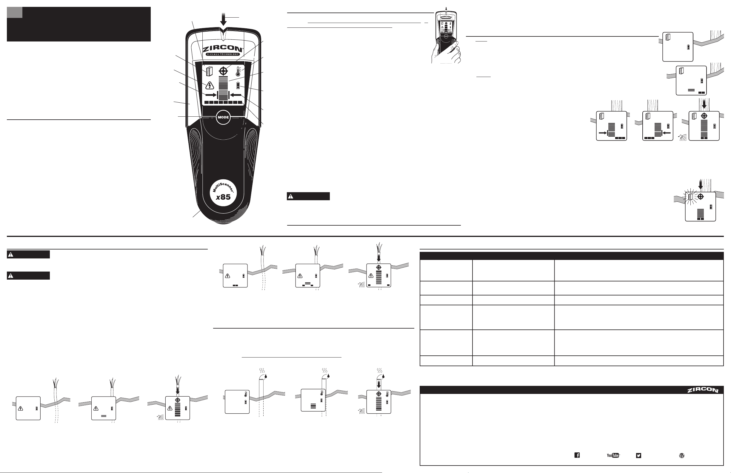
Pointeur SpotLite
™
Écran ACL
rétroéclairé
Mode C.A.
Indicateur de
l´arête gauche
Mode DÉTECTION
DE MONTANTS
(icône de montant
fixe) / Mode
DEEPSCAN
™
(icône de montant
clignotant)
Détecteur
thermique
(arrière de l´outil)
Bouton MODE
Porte du compartiment
des piles (arrière de l´outil)
Indication
du centre
Mode
Thermique
Indicateur
de l´intensité
du signal
Indicateur
de l´état
de la pile
Indicateur de
l´arête droite
Barres
d´indication
de la cible
Détection d´objets autres que des montants
en mode MONTANT.
Localisation d´un plus grand nombre de
cibles qu´il n´en existe réellement
•
Des fils électriques ou des tuyaux en plastique ou en métal
pourraient être situés près de la surface du mur ou y toucher.
• En mode DÉTECTION DE MONTANTS ou en mode C.A., l´outil est
soulevé du mur pendant le balayage ou la main de l´utilisateur ne
se trouve pas continuellement sur l´outil jusqu´à la fin du processus.
•
Balayez la zone en mode C.A. afin de déterminer si des fils c.a. sous tension sont présents.
•
Vérifiez la présence d´autres montants également espacés d´un côté ou de l´autre à 31, 41, ou 61 cm (12, 16, ou 24 po) à plusieurs
endroits plus haut ou plus bas que l´emplacement premièrement balayé.
•
Ne soulevez pas l´outil du mur et gardez continuellement la main sur l´outil jusqu´à la fin du balayage.
Situation Cause probable Solution
Vous soupçonnez la présence de
fils électrique, mais vous n´en avez détecté
aucun.
En mode Thermique, indication constante
du centre ou aucune indication.
L´outil se comporte de manière erratique
ou donne des lectures incohérentes.
•
Les variations de température sont très minimes.
• La vitesse du balayage n’est peut-être pas optimale.
•
Les piles sont faibles.
•
Augmentez le réglage du chauffage par rayonnement afin d´obtenir des variations de température plus perceptibles.
• La vitesse du balayage doit être rapide et continue (environ 30 cm [12 po] par seconde) pour ce mode particulier; un balayage effectué à une
vitesse très faible est trop lent et un balayage effectué plus rapidement n’est pas optimal.
• Ne placez aucune partie du corps, comme les mains, les coudes, les bras ou les pieds, sur la surface à balayer ou à proximité de celle-ci.
Des chaussures doivent être portées pendant le balayage d´un plancher. L´empreinte d´une main peut être détectée jusqu´à 20 secondes ou plus
après que la main a été retirée de la surface.
•
Remplacez les piles par trois piles AAA (LR03) neuves.
•
Les fils électriques pourraient ne pas être sous tension.
•
Les fils électriques sont près d’un cadre de porte en métal ou sont
blindés par un conduit en métal, une couche de fils tressés ou un
revêtement mural métallique.
•
Les fils électriques situés à plus de 51 mm (2 po) de profondeur
pourraient ne pas être détectés.
•
Actionnez les interrupteurs des prises.
•
Branchez une lampe dans une prise murale, puis allumez-la.
Remarque : L’outil MultiScanner® x85 ne peut pas détecter les fils électriques situés à proximité des cadres de porte en métal,
blindés par un conduit en métal ou une couche de fils tressés, ou se trouvant à une profondeur de plus de 50 mm (2 po).
Vérifiez ces conditions avant le balayage.
Détection constante de montants à
proximité de portes ou de fenêtres.
Les zones de tension semblent beaucoup
plus grandes que le fil réel (c.a. seulement).
•
Des montants doubles ou triples se trouvent habituellement de
chaque côté des portes et des fenêtres. Des linteaux se trouvent
habituellement au-dessus des portes et des fenêtres.
•
La détection de la tension peut s´épandre sur les cloisons sèches
d´autant que 31 cm (12 po) de chaque côté d´un fil électrique.
•
Éloignez davantage l´outil de la fenêtre ou de la porte pour l´étalonnage afin de détecter les montants avec plus de précision.
•
Pour limiter la détection, étalonnez de nouveau l’outil x85 dans la zone de l’intensité maximale du champ c.a. ou à l’endroit où
l’indication de c.a. la plus forte a d’abord été observée, puis balayez de nouveau la surface.
GARANTIE LIMITÉE UN AN
La société Zircon (« Zircon ») garantit ce produit libre de tous défauts de matériaux et de fabrication pendant
un an à partir de la date d´achat. Tout produit défectueux selon la garantie retourné à Zircon, frais de transport
prépayés avec une preuve d´achat datée et 5,00 $ pour couvrir les frais de poste et de manutention sera
réparé ou remplacé, à la discrétion de Zircon. Cette garantie est limitée au circuit électronique et au boîtier
original du produit et exclut spécifiquement les dommages causés par toute mauvaise utilisation, utilisation
déraisonnable ou négligence. Cette garantie remplace toutes autres garanties expresses ou indirectes et aucune
autre représentation ou réclamation de quelque sorte que ce soit n´obligera ou ne liera Zircon. Toutes autres
garanties indirectes applicables à ce produit sont limitées à une période d´un an suivant l´achat. DANS AUCUN
CAS ZIRCON NE SERA TENUE RESPONSABLE DE TOUS DOMMAGES INDIRECTS OU CONSÉCUTIFS SUITE À LA
POSSESSION, L´UTILISATION OU LE MAUVAIS FONCTIONNEMENT DE CE PRODUIT.
Conformément aux règlements gouvernementaux, vous êtes avisé que : (i) certains états n´acceptent pas de
limites quant à la durée de la garantie implicite, donc il se peut que les limites et / ou les exclusions précédentes
ne s´appliquent pas dans votre cas et de plus, (ii) cette garantie vous donne certains droits juridiques précis et
vous pouvez aussi en avoir d´autres qui varient d´un état à l´autre.
Retournez le produit frais de transport prépayés avec une preuve d´achat datée et 5,00 $ pour couvrir les frais de
poste et de manutention à :
Zircon Corporation
*Attn: Returns Department
1580 Dell Avenue
Campbell, CA 95008-6992 USA
Assurez-vous d´inclure vos nom et adresse de retour. Les réparations et entretien hors garantie, lorsque la preuve
d´achat n´est pas fournie, seront retournés avec les frais de réparation par envoi contre remboursement. Allouez
4 à 6 semaines pour la livraison.
Service à la clientèle : 1-800-245-9265 ou 1-408-963-4550
Du lundi au vendredi, 8 h à 17 h HNP
courriel : [email protected]
© 2014 Zircon Corporation • P/N 65765 • Rev E 05/16
Visit www.zircon.com/support for the most current instructions.
ACT, DeepScan, MultiScanner, OneStep, SpotLite, et Zircon sont des marques de commerce déposées ou des marques
de commerce de Zircon Corporation.
*Les montants en bois pourraient seulement être détectés à 38 mm (1,5 po)
de profondeur ou moins.
Avertissement concernant un appareil de classe B en vertu de la partie 15 des règlements de la FCC
Cet appareil est conforme à la partie 15 des règlements de la FCC. Fonctionnement assujetti aux deux conditions
suivantes : (1) cet appareil ne peut pas causer d’interférence nuisible et (2) cet appareil doit accepter toute
interférence reçue, y compris une interférence qui pourrait entraîner un fonctionnement non voulu.
AVERTISSEMENT
AVERTISSEMENT
AVERTISSEMENT
A
B C
ZirconCorporation ZirconTV
ZirconTools
|
ZirconToolPro
ZirconTools