
1 - ENG
BEFORE OPERATING THIS TOOL, ALL OPERATORS SHOULD STUDY THIS MANUAL
TO UNDERSTAND AND FOLLOW THE SAFETY WARNINGS AND INSTRUCTIONS. KEEP
THESE INSTRUCTIONS WITH THE TOOL FOR FUTURE REFERENCE. IF YOU HAVE ANY
QUESTIONS, CONTACT YOUR BOSTITCH REPRESENTATIVE OR DISTRIBUTOR.
ANTES DE OPERAR ESTA HERRAMIENTA, TODOS LOS OPERADORES DEBERÁN ESTU-
DIAR ESTE MANUAL PARA PODER COMPRENDER Y SEGUIR LAS ADVERTENCIAS SO-
BRE SEGURIDAD Y LAS INSTRUCCIONES. MANTENGA ESTAS INSTRUCCIONES CON LA
HERRAMIENTA PARA FUTURA REFERENCIA, SI TIENE ALGUNA DUDA, COMUNÍQUESE
CON SU REPRESENTANTE DE BOSTITCH O CON SU DISTRIBUIDOR.
LIRE ATTENTIVEMENT LE PRÉSENT MANUEL AVANT D’UTILISER L’APPAREIL. PRÉTER
UNE ATTENTION TOUTE PARTICULIÈRE AUX CONSIGNES DE SÉCURITÉ ET AUX AVER-
TISSEMENTS. GARDER CE MANUEL AVEC L’OUTIL POUR FUTUR RÉFÉRENCE. SI VOUS
AVEZ DES QUESTIONS, CONTACTEZ VOTRE REPRÉSENTANT OU VOTRE CONCESSI-
ONNAIRE BOSTITCH.
OPERATION and MAINTENANCE MANUAL
MANUAL DE OPERACIÓN Y DE MANTENIMIENTO
MANUEL D’INSTRUCTIONS ET D’ENTRETIEN
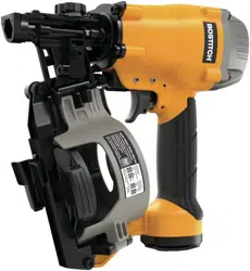
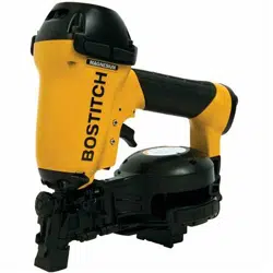
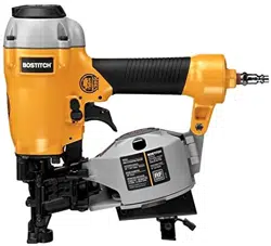
BRN175
COIL ROOFING NAILER
CLAVADORA PARA TECHOS CON BOBINA
CLOUEUSE DE TOITURE À ROULEAU
BOSTITCH FASTENING SYSTEMS
9R209323RA 01/15
BRN175_9R209323_MAN_kf V2_multi.indd 1 1/28/15 7:41 AM
3 - ENG
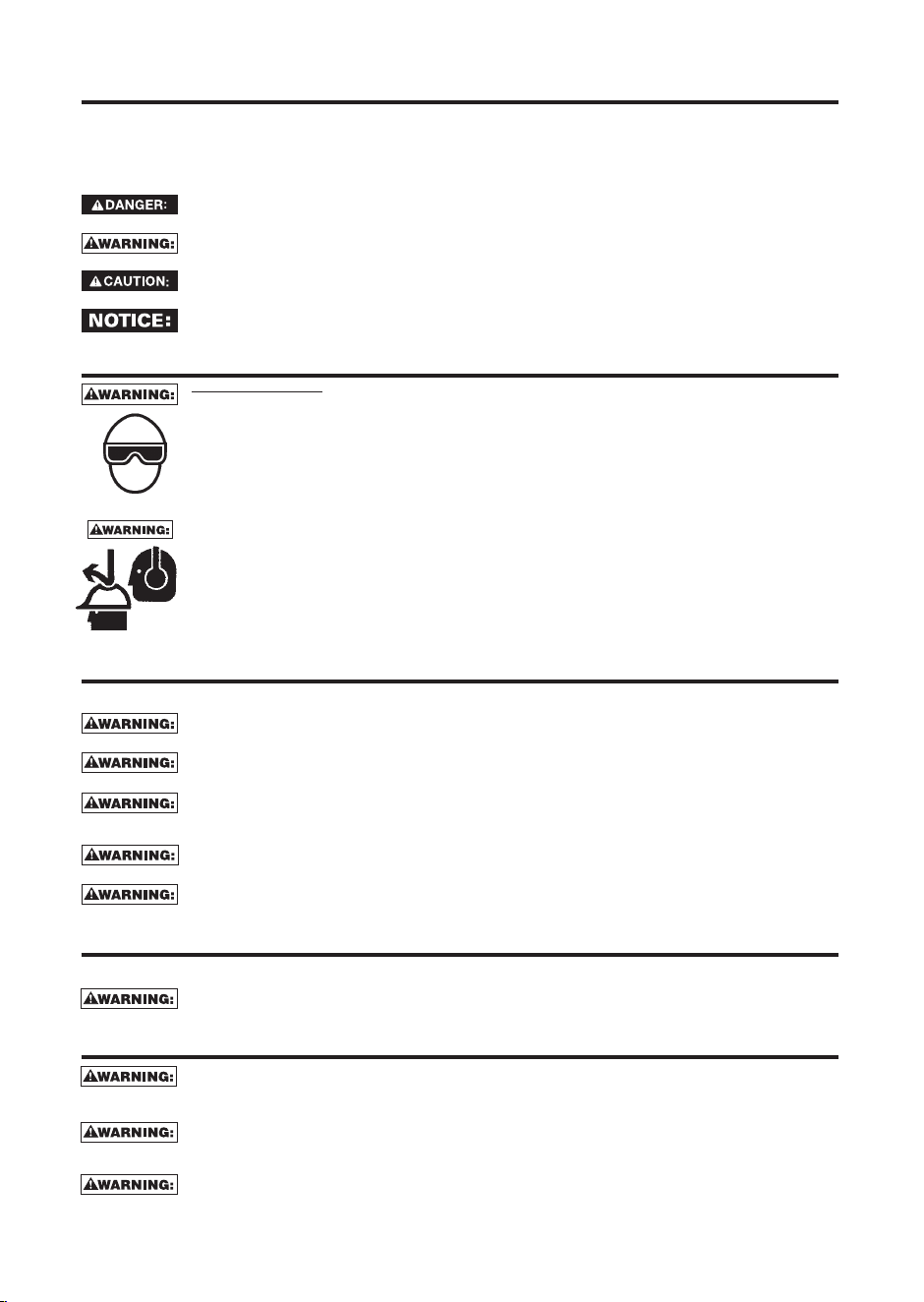
DEFINITIONS - SAFETY GUIDELINES
When using any pneumatic tool, all safety precautions , as outlined below, should be followed to avoid the
risk of death or serious injury. Read and understand the instructions before operating the tool. This manual
contains information that is important for you to know and understand. This information relates to protecting
YOUR SAFETY and PREVENTING EQUIPMENT PROBLEMS. To help you recognize this information, we use the
symbols below. Please read the manual and pay attention to these symbols.
Indicates an imminently hazardous situation which, if not avoided, will result in death or
serious injury.
Indicates a potentially hazardous situation which, if not avoided, could result in death or
serious injury.
Indicates a potentially hazardous situation which, if not avoided, may result in minor or
moderate injury.
Indicates a situation which, if not avoided, may result in property damage.
SAFETY INSTRUCTIONS
EYE PROTECTION which conforms to ANSI specifications and provides protection against
flying particles both from the FRONT and SIDE should ALWAYS be worn by the operator and
others in the work area when connecting to air supply, loading, operating or servicing this
tool. Eye protection is required to guard against flying fasteners and debris, which could
cause severe eye injury.
The employer and/or user must ensure that proper eye protection is worn. Eye protection
equipment must conform to the requirements of the American National Standards Institute,
ANSI Z87.1 and provide both frontal and side protection. NOTE: Non-side shielded spectacles
and face shields alone do not provide adequate protection.
Additional Safety Protection will be required in some environments. For example, the
working area may include exposure to noise level which can lead to hearing damage. The
employer and user must ensure that any necessary hearing protection is provided and used
by the operator and others in the work area. Some environments will require the use of
head protection equipment. When required, the employer and user must ensure that head
protection conforming to ANSI Z89.1 is used.
AIR SUPPLY AND CONNECTIONS
Do not use oxygen, combustible gases, or bottled gases as a power source for this tool as
tool may explode, possibly causing injury.
never connect to a supply which can exceed 200 psi as tool may burst, possibly causing
injury.
The connector on the tool must not hold pressure when air supply is disconnected. If a wrong
fitting is used, the tool can remain charged with air after disconnecting and thus will be able
to drive a fastener even after the air line is disconnected possibly causing injury.
Do not pull trigger or depress contact arm while connected to the air supply as the tool may
cycle, possibly causing injury.
Always disconnect air supply: 1.) Before making adjustments; 2.) When servicing the tool; 3.)
When clearing a jam; 4.) When tool is not in use; 5.) When moving to a different work area, as
accidental actuation may occur, possibly causing injury.
LOADING TOOL
When loading tool: 1.) Never place a hand or any part of body in fastener discharge area
of tool; 2.) Never point tool at anyone; 3.) Do not pull the trigger or depress the trip as
accidental actuation may occur, possibly causing injury.
OPERATION
Always handle the tool with care: 1.) Never engage in horseplay; 2.) Never pull the trigger
unless nose is directed toward the work; 3.) Keep others a safe distance from the tool while
tool is in operation as accidental actuation may occur, possibly causing injury.
The operator must not hold the trigger pulled on contact arm tools except during fastening
operation as serious injury could result if the trip accidentally contacted someone or
something, causing the tool to cycle.
Keep hands and body away from the discharge area of the tool. A contact arm tool may
bounce from the recoil of driving a fastener and an unwanted second fastener may be driven
possibly causing injury.
BRN175_9R209323_MAN_kf V2_multi.indd 3 1/28/15 7:41 AM
4 - ENG
Check operation of the contact arm mechanism frequently. Do not use the tool if the arm is
not working correctly as accidental driving of a fastener may result. Do not interfere with the
proper operation of the contact arm mechanism.
Do not drive fasteners on top of other fasteners or with the tool at an overly steep angle as this
may cause deflection of fasteners which could cause injury.
Do not drive fasteners close to the edge of the work piece as the wood may split, allowing the
fastener to be deflected possibly causing injury.
This nailer produces SPARKS during operation. NEVER use the nailer near flammable substances,
gases or vapors including lacquer, paint, benzine, thinner, gasoline, adhesives, mastics, glues or
any other material that is -- or the vapors, fumes or byproducts of which are -- flammable, combustible or explosive.
Using the nailer in any such environment could cause an EXPLOSION resulting in personal injury or death to user
and bystanders.
Use of this product may expose you to chemicals known to the
State of California to cause cancer, birth defects and other reproductive harm.
Avoid inhaling vapors and dust, and wash hands after using.
• Avoid prolonged contact with dust from power sanding, sawing,
grinding, drilling, and other construction activities. Wear protective
clothing and wash exposed areas with soap and water. Allowing dust
to get into your mouth, eyes, or lay on the skin may promote absorption
of harmful chemicals.
Use of this tool can generate and/or disburse dust, which may
cause serious and permanent respiratory or other injury. Always use NIOSH/OSHA
approved respiratory protection appropriate for the dust exposure. Direct particles
away from face and body. Always operate tool in well-ventilated area and provide
for proper dust removal. Use dust collection system wherever possible.
ALWAYS USE SAFETY GLASSES. Everyday eyeglasses are NOT
safety glasses. Also use face or dust mask if operation is dusty. ALWAYS WEAR
CERTIFIED SAFETY EQUIPMENT:
• ANSI Z87.1 eye protection (CAN/CSA Z94.3),
• ANSI S12.6 (S3.19) hearing protection,
• NIOSH/OSHA respiratory protection.
Before operating this tool, carefully read and understand all instructions in
Important Safety Instructions.
SAVE THESE INSTRUCTIONS
NAIL SPECIFICATIONS
BRN175
Nails 0.120" (3mm) diameter, 15º wire collated roofing nails
Lengths 3/4" (19 mm) - 1-3/4" (44.5 mm)
Air Inlet 1/4" NPT (6.4mm)
NOTE: Use only BOSTITCH approved fasteners
MAINTAINING THE TOOL
When working on air tools note the warnings in this manual and use extra care when
evaluating problem tools.
BRN175_9R209323_MAN_kf V2_multi.indd 4 1/28/15 7:41 AM
5 - ENG
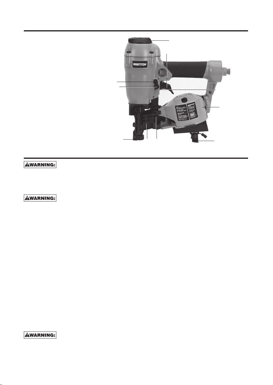
TOOL PARTS:
Fig. 1
A. Exhaust deflector
B. Selectable trigger
C. Canister
D. Door latch
E. Safety contact tip
F. Depth adjustment wheel
G. Door
H. Tool-Free Shingle Guide
I. Trigger lock button
J. Mode selector button
ASSEMBLY:
Disconnect air line from tool, engage trigger lock and remove
fasteners from magazine before making adjustments or personal injury may
result.
TRIGGER
Keep fingers AWAY from the trigger when not driving fasteners to
avoid accidental actuation. Never carry a tool with finger on the trigger. In bump
action mode (contact actuation mode), the tool will drive a fastener if the contact
trip is bumped while the trigger is depressed.
The BRN175 is equipped with a selectable trigger. This trigger allows the operator
to select either single sequential action trigger mode or bump action trigger mode.
In accordance with the ANSI Standard SNT-101-2002, the trigger is assembled
in the single sequential action trigger mode. To change the trigger mode, see
Actuating Tool instructions in the Operation section of the manual. The selectable
trigger also has a trigger lock button to keep the trigger locked at all times when
the tool is not in use.
AIR FITTING
This tool uses a 1/4" N.P.T. male plug. The inside diameter should be .275" (7mm)
or larger. The fitting must be capable of discharging tool air pressure when
disconnected from the air supply. A 3/8" (9.5mm) male quick connector coupling
is available from BOSTITCH and may be used when a 1/4" (6.4mm) supply line is
not available.
NOTE: A 3/8" (9.5mm) supply line (and fittings) are required for maximum tool
performance.
Always use couplings that relieve all pressure from the tool when it
is disconnected from the power supply. Always use hose connectors that shut off
air supply from compressor when the tool is disconnected.
A
E
I
J
F
B
C
H
D
G
BRN175_9R209323_MAN_kf V2_multi.indd 5 1/28/15 7:41 AM
6 - ENG
To install an air fitting
1. Wrap the male end of the fitting with thread seal tape prior to assembly to
eliminate air leaks.
2. To install a 1/4" (6.4mm) fitting: screw it directly into the air inlet and tighten
firmly. NOTE: If an adapter is in the air inlet, remove it prior to inserting the
fitting.
3. To install a 3/8" (9.5mm) fitting: screw the fitting into the 3/8" (9.5mm) adapter
and then into the air inlet of the tool and tighten firmly.
OPERATION:
PREPARING THE TOOL
Read the section titled Important Safety Instructions for Pneumatic
Tools at the beginning of this manual. Always wear eye and ear protection when
operating this tool. Keep the nailer pointed away from yourself and others. For
safe operation, complete the following procedures and checks before each use of
the nailer.
To reduce the risk of damage to the tool, only use BOSTITCH pneumatic
tool oil or a non-detergent SAE 20 weight oil. Oil with additives or detergent will
damage tool parts.
1. Before you use the nailer, be sure that the compressor tanks have been
properly drained.
2. Lubricate tool:
a. Use BOSTITCH pneumatic tool oil or a non-detergent S.A.E. 20 weight oil.
DO NOT use detergent oil or additives as they will damage O-rings and
rubber parts.
b. Use a filter when possible.
c. Add 5 to 7 drops of oil in the air fitting a least twice a day.
3. Wear eye and ear protection.
4. Ensure canister is empty of all fasteners.
5. Check for smooth and proper operation of contact trip. Do not use tool if
assembly is not functioning properly. NEVER tamper with the contact trip.
NEVER use a tool that has the contact trip restrained in the actuated position.
6. Check air supply: Ensure air pressure does not exceed recommended
operating limits; 70 to 120 psi, (4.9 to 8.3 bar, 5 to 8.5 kg/cm
2
).
7. Keep tool pointed away from yourself and others.
8. Connect air hose.
9. Check for audible leaks around valves and gaskets. Never use a tool that leaks
or has damaged parts.
To reduce the risk of personal injury, disconnect tool from air
supply and engage trigger lock before performing maintenance, clearing a
jammed fastener, leaving work area, moving tool to another location or handing
the tool to another person.
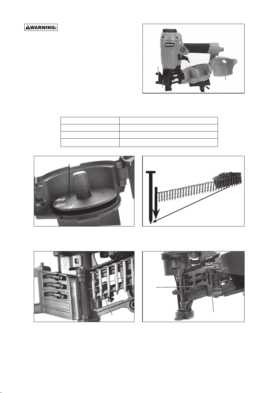
LOADING THE TOOL (FIG. 1–6)
Keep the tool pointed away from yourself and others. Serious
personal injury may result.
BRN175_9R209323_MAN_kf V2_multi.indd 6 1/28/15 7:41 AM
7 - ENG
Never load nails with
the contact trip or trigger activated.
Personal injury may result.
1. Read all Safety Warnings before
using tool.
2. Connect the air supply to the tool.
3. Lift the canister door latch (E) to
open the nail guide door (H).
4. Rotate the canister door (I) open.
5. Adjust the nail platform (J) to
properly accommodate the nail
length being used. Pull the nail platform (J) up or down for desired nail.
Platform Position Nail Length
lowest position 1-1/2" (38 mm) - 1 3/4" (44.5mm)
center position 1-1/4" (32 mm)
upper position 3/4" (19 mm) - 1" (25 mm)
6. Place the coil on the nail platform (J). NOTE: Observe fastener icon (K) Fig. 4.
Insert fasteners (L) with points down.
IMPORTANT: Fasteners must point in the same direction as they will be driven.
7. Uncoil enough nails [approximately 3" (76mm)] to reach the nose of the tool.
8. Insert the first nail into the nose and the second nail (M) between the two rails
of the feed pawl as shown in Fig. 5.
Fig. 2
E
H
I
Fig. 3
J
Fig. 5
M
Fig. 6
E
H
Fig. 4
K
L
BRN175_9R209323_MAN_kf V2_multi.indd 7 1/28/15 7:41 AM
8 - ENG
NOTE: Be careful not to deform the coil of nails during the loading process.
Otherwise, the nail guide door will not close and the nails might not feed
consistently.
9. Close the canister door (I) completely.
10. Close the nail guide door (H) making sure the
door latch (E) is completely engaged as shown
in Fig. 6.
ACTUATING TOOL:
To reduce the risk of injury, A LWAYS
wear proper eye ANSI Z87.1 (CAN/CSA Z94.3)
and hearing protection ANSI S12.6 (S3.19) when
operating this tool. The tool can be actuated using
one of two modes: single sequential actuation
trigger mode and contact actuation trigger mode.
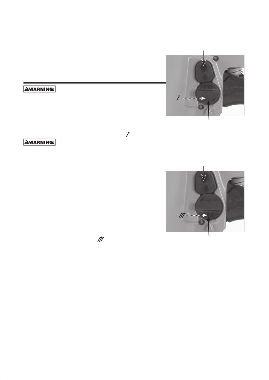
Single Sequential actuation trigger -
(Fig. 7)
Allow the tool to recoil off the work surface after actuation. If
the contact trip remains depressed a nail will be driven each time the trigger is
released and pulled, which could result in accidental actuation, possibly causing
injury.
The sequential actuation trigger’s intended use is
for intermittent fastening where accurate fastener
placement is desired.
To operate the tool in Single sequential actuation
mode:
1. Depress the contact trip firmly against the
work surface.
2. Pull the trigger.
3. Allow the tool to recoil from the work surface.
Contact actuation trigger -
(Fig. 8)
The contact actuation trigger is intended for rapid fastening on flat, stationary
surfaces.
Using the contact actuation trigger, two methods are available: place actuation
and contact actuation.
To operate the tool using the PLACE ACTUATION method:
1. Depress the contact trip against the work surface.
2. Pull the trigger to drive the fastener.
3. Allow the tool to recoil off the work surface
To operate the tool using the CONTACT ACTUATION method:
1. Pull the trigger.
2. Depress the contact trip against the work surface. As long as the trigger is
pulled, the tool will drive a fastener every time the contact trip is depressed.
This allows the user to rapidly drive multiple fastener in sequence.
Fig. 8
C
Trigger lock button
Trigger mode selector button
Fig. 7
S
Trigger lock button
Trigger mode selector button
BRN175_9R209323_MAN_kf V2_multi.indd 8 1/28/15 7:41 AM
9 - ENG
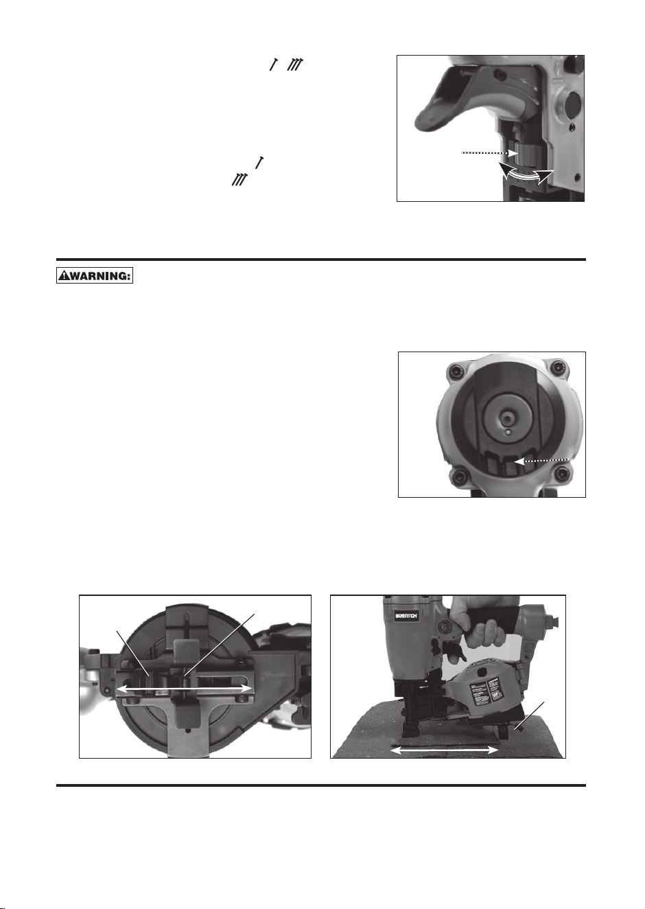
Changing the Actuation Mode -
1. Push the (red) trigger lock button down
2. Rotate the (black) selectable trigger button
counterclockwise
3. Align the triangular indicator to the desired
mode
• For Sequential Mode
• For Contact Mode
4. Then push the trigger lock button back up to
the un-locked position.
ADJUSTING DEPTH (FIG. 9):
To reduce risk of serious injury from accidental actuation when
attempting to adjust depth, ALWAYS:
• Disconnect air supply and engage trigger lock.
• Avoid contact with trigger during adjustments.
The depth that the fastener is driven can be adjusted using the depth adjustment
next to the trigger of the tool.
The depth of drive
is factory adjusted to a nominal setting. Test
drive a fastener and check depth. If a change is
desired:
1. To drive the nail shallower, rotate the depth
setting wheel (G) to the right.
2. To drive a nail deeper, rotate the depth setting
wheel (G) to the left.
The adjustment knob has detents every 1/4 turn.
Test drive another fastener and check depth.
Repeat as necessary to achieve desired results. The amount of air pressure
required will vary depending on the size of the fastener and the material being
fastened. Experiment with the air pressure setting to determine the lowest set-
ting that will consistently perform the job at hand. Air pressure in excess of that
required can cause premature wear and/or damage to the tool.
DIRECTIONAL EXHAUST DEFLECTOR:
Adjust directional exhaust deflector (A) Fig. 10, so that the exhaust air blast will
be directed away from the operator. The exhaust deflector can be adjusted any
position for directing the exhaust blast away from the operator. Grasp the deflec-
tor and rotate it to the desired position for the current application.
Fig. 9
G
Fig. 10
A
Fig. 11
O
P
Fig. 12
R
O
Q
BRN175_9R209323_MAN_kf V2_multi.indd 9 1/28/15 7:41 AM
10 - ENG
SHINGLE GUIDE (FIG. 11, 12)
Adjust shingle guide (O):
1. Loosen the adjusting lever (P) and slide the
locking plate to desired position.
2. Tighten adjusting lever firmly.
The locking plate (O) can be used as an aid to
position the shingle being nailed a specific
distance (Q) from the front edge of the previous
row of shingles (R) as shown.
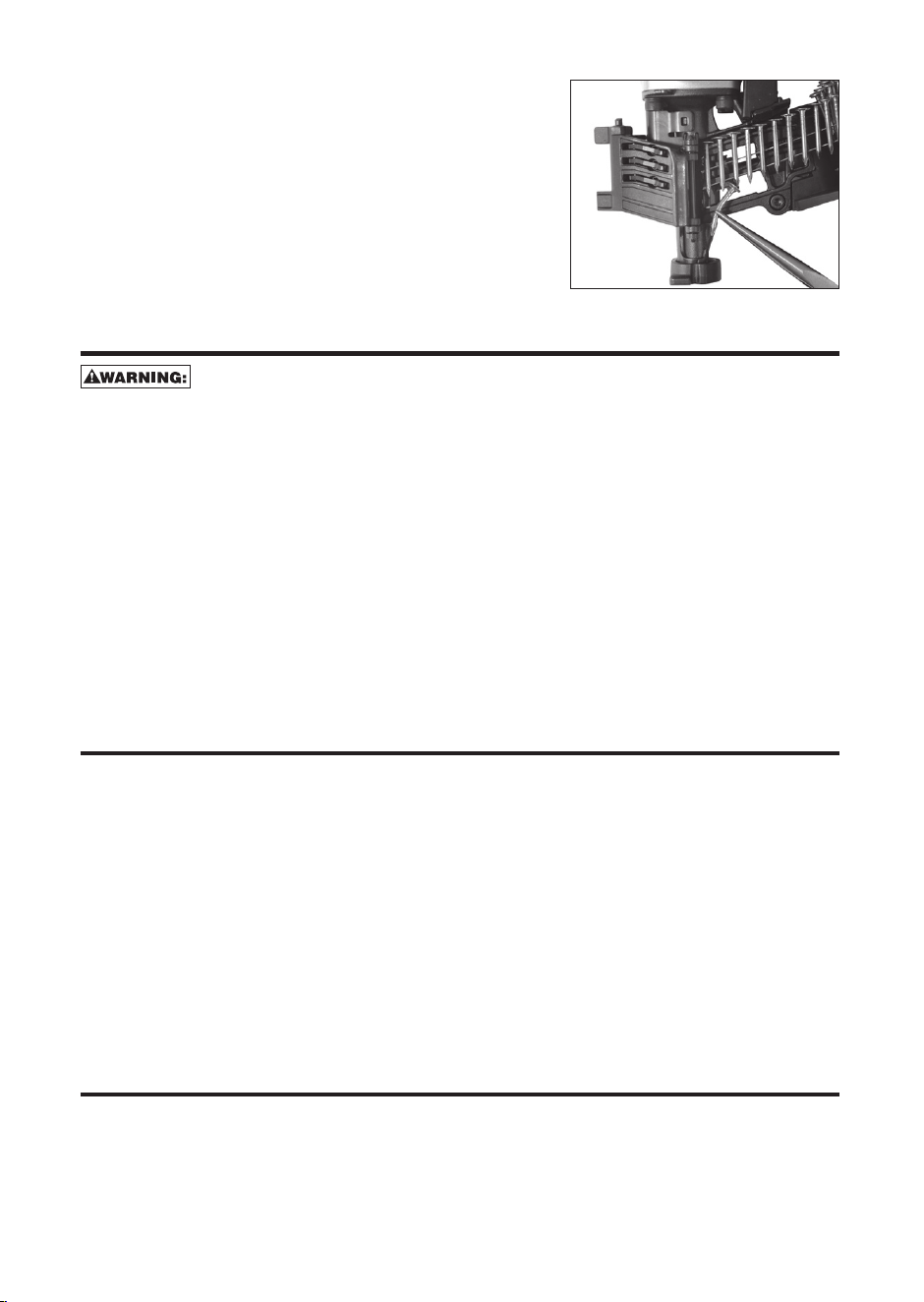
CLEARING A JAMMED NAIL (FIG. 1,9)
Disconnect air line from tool, engage trig-
ger lock lift the canister door latch, open the canister door, and remove
fasteners from magazine before making adjustments or personal injury may
result.
If a nail becomes jammed in the nosepiece, keep the tool pointed away from you
and follow these instructions to clear:
1. Disconnect the air supply from the tool.
2. Engage trigger lock.
2. Lift the canister door latch (E) to open the nail guide door (H).
3. Open the canister door.
4. Remove the jammed nail.
5. Correct any deformation that may have occurred to the nail coil.
NOTE: Should nails continue to jam frequently in nosepiece, have tool serviced by
an authorized BOSTITCH service center.
COLD WEATHER OPERATION
When operating tools at temperatures below freezing:
1. Make sure compressor tanks have been properly drained prior to use.
2. Keep tool as warm as possible prior to use.
3. Make certain all fasteners have been removed from canister.
4. Put 5 to 7 drops of BOSTITCH pneumatic tool oil in the air inlet.
5. Lower air pressure to 80 psi (5.5 bar) or less.
6. Reconnect air and load nails into canister.
7. Actuate the tool 5 or 6 times into scrap lumber to lubricate O-rings.
8. Turn pressure up to operating level (not to exceed 120 psi) and use tool as
normal.
9. Re-lubricate at least once daily.
10. Always drain the compressor tanks at least once a day.
HOT WEATHER OPERATION
Tool should operate normally. However, keep tool out of direct sunlight as
excessive heat can deteriorate bumpers, O-rings and other rubber parts resulting
in increased maintenance.
Fig. 13
BRN175_9R209323_MAN_kf V2_multi.indd 10 1/28/15 7:41 AM