Owner's manual and Installation instructions Ranges
USING THE HOOD
Controls
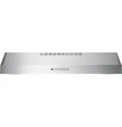
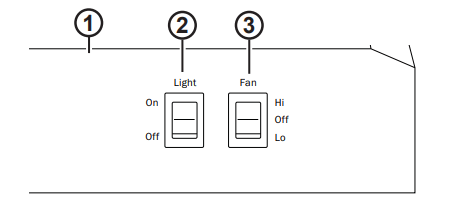
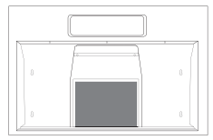
Rangehood Control Panel: The control panel is located on the front of the canopy.
Light Switch: Light switch toggles between On and Off.
Fan Power Switch: The power switch toggles between fan settings Hi, Lo, and Off.
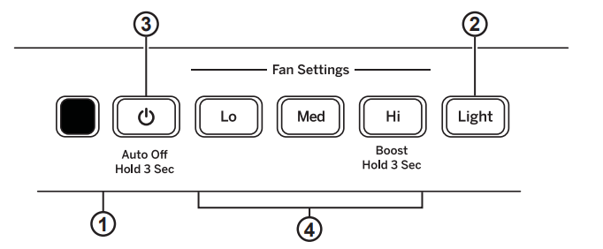
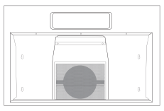
Rangehood Control Panel: The control panel is located on the front of the canopy.
Light Button: On/Light/Off switch for the lights. Press the LIGHT button to turn the lights on, again to set the lights to night setting, and again to turn off.
Fan Off Button: Off switch for the fan. The fan can be operated by pressing any of the fan setting buttons. Hold for 3 seconds to activate auto off after 15 minutes.
Fan Settings Buttons: Speed control for fan. Press the button Lo for LOW speed, Med for MEDIUM speed and Hi for HIGH speed. Hold down the Hi button for 3 seconds to activate the BOOST SPEED that will run for 10 minutes.
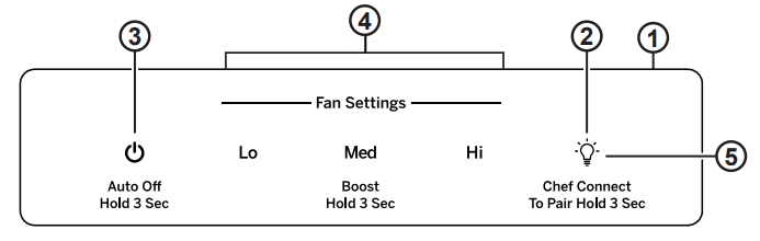
Rangehood Control Panel: The glass touch control panel is located on the front of the canopy.
Light Pad: On/Light/Off switch for the lights. Press the LIGHT pad to turn the lights on, again to set the lights to night setting, and again to turn off.
Auto Off Pad: Off switch for the fan. The fan can be operated by pressing any of the fan setting pads. Hold for 3 seconds to activate auto off after 15 minutes.
Fan Settings Pads: Speed control for fan. Press the pad Lo for LOW speed, Med for MEDIUM speed and Hi for HIGH speed. Hold down the Hi button for 3 seconds to activate the BOOST SPEED that will run for 10 minutes.
Chef Connect: This is a Bluetooth® pairing feature for use with other compatible Chef Connect enabled products on a cooktop or a range. When the device is paired, the light and fan will turn ON at the Default Sync Settings upon receiving a command from the range or cooktop. It will remain ON at that setting until the user changes it.
Chef Connect
Chef Connect Operation Bluetooth® Connection
To pair with another device:
To start the pairing process on the hood, press and hold the Light pad for 3 seconds. The backlight for the Lo – Med – Hi – Light will flash in that sequence until the hood is paired with the range or other device. If the pairing is successful, all 4 lights (Lo, Med, Hi, and Light) will flash three times simultaneously and then turn off. It will time out after 2 minutes if pairing is not completed. After which the pairing sequence will need to be restarted.
To cancel pairing:
To cancel the pairing hold the Light pad for 3 seconds and then turn off the hood.
Default Sync Settings:
The factory default setting for the light will be the brightest.
The factory default setting for the fan sync will be OFF.
The user can change the Default Sync Settings by pressing and holding the Lo pad for 3 seconds. This will enter the Default Settings Mode. Once in this mode, the backlights for all buttons (Lo, Med, Hi, and Light) will blink On/Off indefinitely and the fan and light will switch to the current Default Sync Setting, so the user knows, what the current default value is. At this time. set the light and fan to the desired default levels. Once the user is satisfied with the selection. press and hold the Off pad for 3 seconds. This will exit this mode. At that time the backlights will stop blinking and the state of the fan and light will change back to their prior state before entering the Default Settings Mode.
CARE AND CLEANING
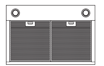
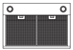
Metal Grease Filter
The metal filters trap grease during cooking. The filter must ALWAYS be in place when the hood is in use. The grease filter is dishwasher-safe and should be cleaned every 6 months, or as needed.
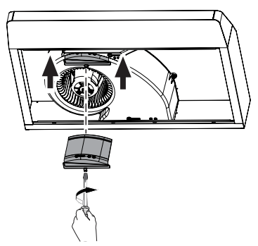
To remove: Pull downward on the filter lock to release the filter.
To replace: Fit the tabs at the bottom of the filter into the slots in the back of the filter opening. Lift up the front side of the filter and push gently until the filter locks into place. Make sure the filter lock is in the closed position to secure the filter.
To clean, swish the filter in hot soapy water and rinse in clean water or wash it in the dishwasher. Do not use abrasive cleansers.
NOTE: Some discoloration may occur in the dishwasher.
Stainless Steel Surfaces (on some models)
Do not use a steel wool pad; it will scratch the surface.
To clean the stainless steel surface, use warm sudsy water or a stainless steel cleaner or polish. Always wipe the surface in the direction of the brush line. Follow the cleaner instructions for cleaning the stainless steel surface. Cleaners with oxalic acid such as Bar Keepers Friend Soft Cleanser™ will remove surface rust, tarnish, and small blemishes.
Use only a liquid cleanser free of grit and rub in the direction of the brush lines with a damp soft sponge.
Painted Surfaces (on some models)
Do not use a steel wool pads or other abrasive cleaners; they will scratch the surface.
Clean grease-laden surfaces of the hood frequently. To clean the hood surface, use a hot, damp cloth with a mild detergent suitable for painted surfaces. About one tablespoon of ammonia may be added to the water. Use a clean, hot, damp cloth to remove soap. Dry with a dry, clean cloth.
NOTE: When cleaning, take care not to come in contact with filters and other surfaces.
CAUTION! When cleaning the hood surfaces, be certain that you do not touch the light with moist hands or cloth. A warm or hot light may break if touched with a moist surface. Always let the light cool completely before cleaning around it.
Lights
CAUTION! Allow lights to cool before touching.
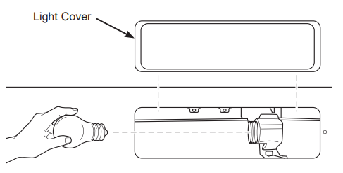
Before attempting to replace the lights, make sure that the light switch is turned off.
Remove light cover.
Unscrew light counterclockwise to unlock light and pull out.
Replace with new light of same type (standard incandescent), making sure socket is properly inserted into the housing of the lamp holder.
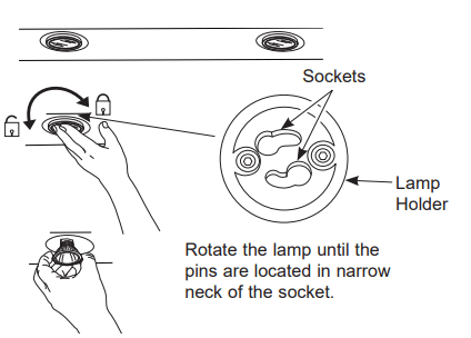
Before attempting to replace the lights, make sure that the light switch is turned off.
Rotate light counterclockwise to unlock and pull out. Wearing latex gloves may offer a better grip.
Replace with new light of same type, making sure pins are inserted properly into the sockets of the lamp holder and turn clockwise to lock.
All lamps need to be GU10 compatible.
Troubleshooting tips
Problem
Possible Cause
What To Do
Fan/Light does not operate when either button is pressed
A house fuse may be blown or a circuit breaker tripped.
Replace fuse or reset circuit breaker.
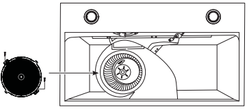
Fan does not operate when fan Lo, Med, Hi buttons are pressed
The blower connector is loose or not plugged into its mating connector.
Disconnect power to the unit. Remove the filters and look up at the blower. If the blower connector plug is loose or you see the connector dangling, the installer failed to plug it in securely. See the mini manual for the plug location and how to plug in the connector.
Loud or abnormal airflow noise
Wrong duct size used in installation.
Using smaller duct pipe will cause reduced venting. Minimize the duct run length and number of transitions and elbows. GE service technicians cannot correct this issue if installed improperly.
Fan fails to circulate air or moves air slower than normal and/or fan is making loud or abnormal airflow noise
Obstructions in duct work.
Make sure nothing is blocking the vent. Make sure your wall or roof cap has a blade or door.
Damper blade on wall or roof cap may not be open.
Make sure damper swings freely. Damper blades may flip over and will not fully open when this happens. Adjust to original position.
Metal grease filter and charcoal filter (if present) may be dirty.
Clean the metal grease filter and replace charcoal filter (if present). See Care and Cleaning of the Vent Hood.
Insufficient makeup (replacement) air
Sufficient makeup (replacement) air is required for exhausting appliances to operate to rating. Check with local building codes, which may require or strongly advise the use of makeup air.
The hood controls are not operating correctly
Control logic confused.
Disconnect power to the hood by resetting the circuit breaker. Wait 30 seconds to allow controls to reset.
Early light failure
Light wattage is too high.
Replace with correct wattage.
Fan continually cycles off and on
The motor is probably overheating and turning itself off. This can be harmful to the motor. Filter may be excessively soiled.
Clean the metal grease filter and replace charcoal filter (if present). See Care and Cleaning of the Vent Hood.
INSTALLATION INSTRUCTIONS
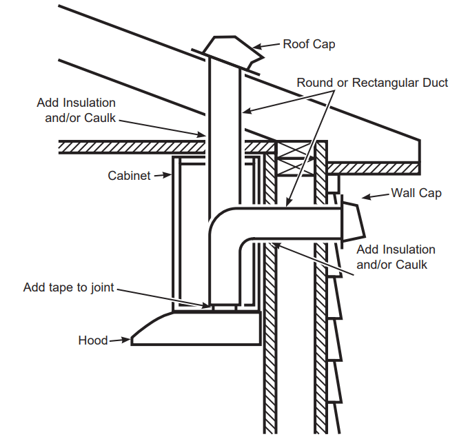
INSULATION AND/OR CAULK AROUND THE DUCTS
INSTALLATION PREPARATION
1. SELECT VENT OPTION THAT YOUR INSTALLATION WILL REQUIRE (A-D)
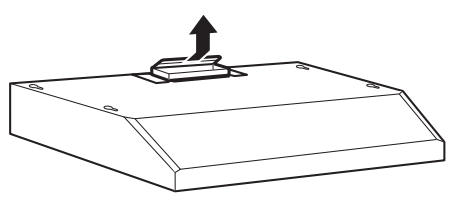
Outside top exhaust (Vertical duct—3 1»4” x 10” Rectangular)
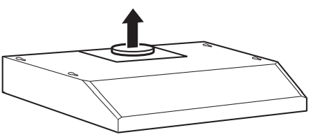
Outside top exhaust (Vertical duct—7” Round)
Outside rear exhaust (Horizontal duct—3 1»4” x 10” Rectangular)
Recirculating (Unit is configured from factory in this mode)
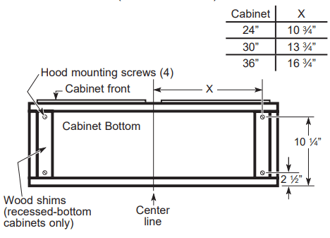
2. PREPARING MOUNTING
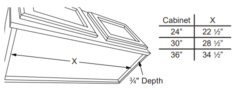
For cabinets with dimensions below, the mounting bracket may be used for any model. Otherwise, the hood must mount directly to bottom of cabinet. Wood shims may be needed for cabinets with a recessed bottom. Skip to step B.
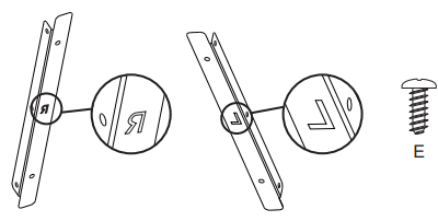
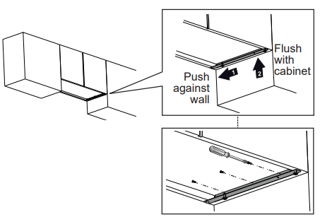
A. To install the mounting bracket Drive (E) screws in partway into mounting bracket. The bracket labeled "R" will be used on the right side of the cabinet and the bracket labeled "L" will be used on the left side of the cabinet. Under the cabinet that you are placing the range hood, attach the mounting bracket as shown below with (F) screws. Make sure orientation is correct. Brackets should be located against the back wall and flush with the bottom of the cabinet. NOTE: Repeat on left side.
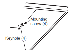
B. To install to the bottom of cabinet Use the diagram or hood as a template and mark the locations on the cabinet for the keyholes screws. Drive the 4 (F) screws partway into the bottom of the cabinet (or wood shims).
3. PREPARE FOR ELECTRICAL AND VENTING
Select the vent option that your installation will require and proceed to that section:
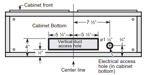
Outside top exhaust (Vertical duct–3 1»4” x 10” Rectangular)
Use the diagram as a template and mark the locations on the cabinet for ductwork and electrical wiring.
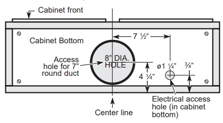
Outside top exhaust (Vertical duct–7” Round)
Use the diagram as a template and mark the locations on the cabinet for ductwork and electrical wiring.
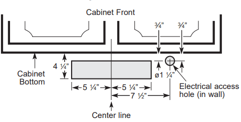
Outside rear exhaust (Horizontal duct–3 1»4” x 10” Rectangular)
Use the diagram as a template and mark the locations on the cabinet for ductwork and electrical wiring.
4. REMOVE ELECTRICAL KNOCKOUTS
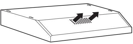
Use a flat blade screwdriver, remove the appropriate electrical knockout from the back or the top of the hood.
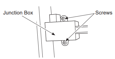
5. REMOVE JUNCTION BOX
Remove junction box from inside the hood. Set the junction box and mounting screws aside.
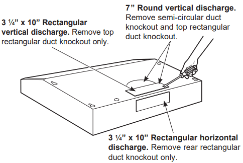
6. REMOVE DUCT KNOCKOUT(S) FOR VENTED INSTALLATION
Determine which ducting option to use. Using a flat blade screwdriver, remove the appropriate duct knockout(s) from the top or back of the hood.
NOTE: If the hood is to be installed in a recirculation, non-vented ductless manner, do not remove any venting knockouts.
NOTE: For an ENERGY STAR® model, unit must be vented mode to be considered ENERGY STAR® certified.
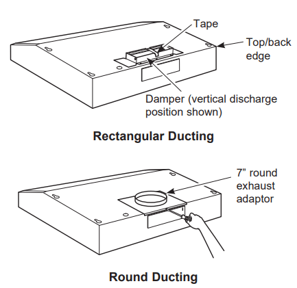
7. ATTACH DAMPER/DUCT CONNECTOR
Attach damper/duct connector over knockout opening with two or four (D) screws. Make sure damper pivot is nearest to top/back edge of hood. Remove any packaging tape to allow damper to move freely.
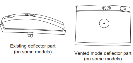
8. FOR VENTED INSTALLATIONS
On Some Models: Install with vented mode deflector part.
On Some Models: The existing deflector part must be removed. To remove the existing deflector piece, unscrew to remove it. Install the vented mode deflector part included in hardware kit using the screw. The deflector must be installed to prevent leakage in case of vented installation.
On Some Models: Remove, rotate, and re-install deflector part for vented mode.
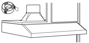
9. FEED IN WIRES
Lift the hood into position and feed the house wiring through the wiring knockout.
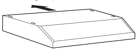
10. MOUNT THE UTC
Place the hood onto the partially installed screws using the keyholes and slide the hood back into position.
11. SECURE HOOD
Tighten the mounting screws. Be sure the screw heads are in the narrow neck of the keyhole slot.
12. CONNECT DUCTWORK TO HOOD (Ducted installations only)
Connect ducting to hood. Use duct tape to make joints secure and airtight.
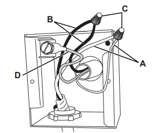
13. ELECTRICAL CONNECTION
Connect the Power Supply Cable to the range hood. Attach the white lead of the power supply to the white lead of the range hood (A) with a wire nut (C). Attach the black lead of the power supply to the black lead of the range hood (B) with a wire nut (C). Connect the green (D) ground wire under the green grounding screw.
Replace the junction box cover.
14. FINISH THE INSTALLATION
On Some Models:
For recirculation: Install the charcoal filter.
For ducted installation: Install the grease filters.
On Some Models:
For recirculation: Place the charcoal filter (not included) in place and mount using 2 screws. Replace the grease filters.
For vented installation: Install the grease filters.
Additionally, the document applies to other GE - General Electric models: JVX3240*, JVX3300*, JVX5300*, JVX5360*, JVX5305*, JVX5365*, PVX7300*, PVX7360*