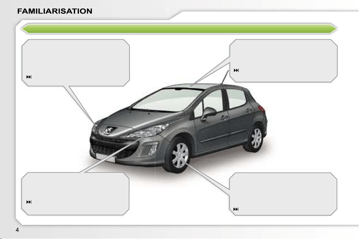
EXTERIOR
Welcome lighting
This additional exterior and interior light-
ing, controlled remotely, makes your
approach to the vehicle easier when the
light is poor.
79, 86
Directional lighting
This lighting automatically provides ad-
ditional visibility when cornering.
81
Glass panoramic roof
This roof provides incomparable visibil-
ity and light in the passenger compart-
ment.
75
Lane departure warning system
This equipment warns you if you inad-
vertently cross a longitudinal marking
on the ground.
127
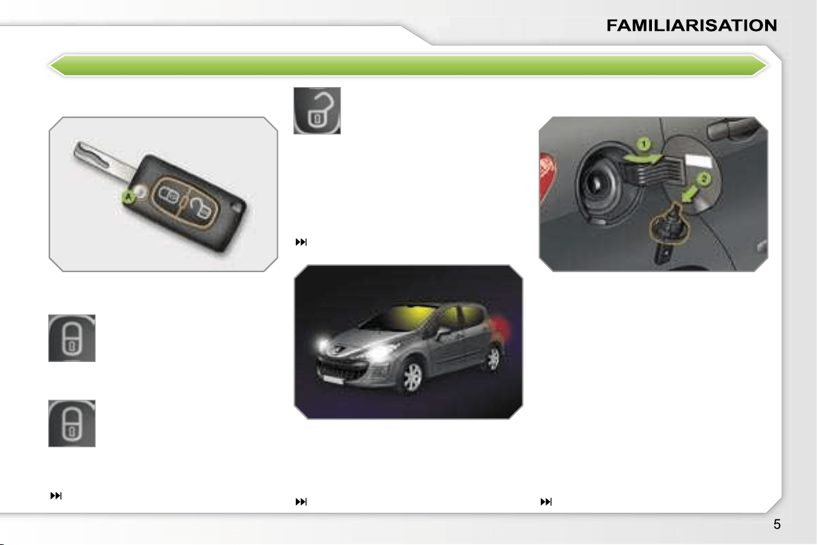
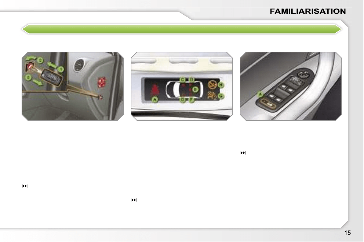
OPEN
Remote control key
A.
Unfolding/Folding of the key.
Normal locking
(press once)
(fixed lighting of the direction
indicators).
Fuel tank
1.
Opening of the fuel filler flap.
2.
Opening and hooking of the fuel
tank cap.
Capacity of the tank: approximately
60 litres.
Complete or selective unlock-
ing of the vehicle
(rapid flashing of the direction
indicators).
When the light is poor, detected by
a sensor, the remote switching on of
the dipped headlamps and side lights
makes your approach to the vehicle
easier.
79
In the same way, the passenger com-
partment lighting, such as the courtesy
lights, the sill lights and the footwell
lights, comes on.
or
Deadlocking of the vehicle
(press twice in succession)
(fixed lighting of the direction
indicators).
63
86
76
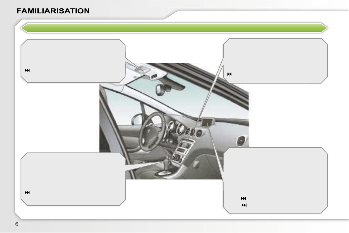
INTERIOR
Ambient lighting
This dimmed lighting of the passenger
compartment facilitates visibility inside
the vehicle when the light is poor.
86
6-speed piloted manual gearbox
This equipment offers driving combining
a fully automatic mode, a manual mode
and an auto-sequential mode which
combines the advantages of the other
two modes.
116
Fragrance diffuser
This fragrance diffuser diffuses the fra-
grance that you have selected through-
out the passenger compartment by
means of its location in the central vent.
53
Audio and communication
systems
This equipment benefits from the latest
technology: MP3 compatible RD4 audio
equipment, Bluetooth hands-free kit,
RT4 GPS audio/telephone with retract-
abe colour screen, JBL audio system,
auxiliary sockets.
RT4
171
RD4
201
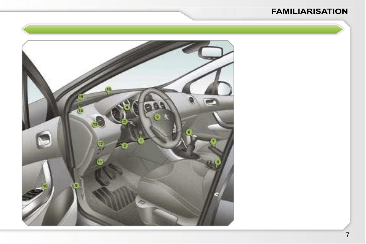
INSTRUMENTS AND CONTROLS
1.
Cruise control/speed limiter switch.
2.
Steering wheel adjustment control.
3.
Lights and direction indicators
controls.
4.
Instrument panel.
5.
Driver’s air bag.
Horn.
6.
Gear lever.
7.
Handbrake.
8.
Panoramic roof shutter control.
9.
Bonnet release.
10.
Exterior mirror controls.
Electric window controls.
11.
Fuse box.
12.
Manual headlamp height
adjustment.
Lane departure warning system
button.
13.
Side adjustable and closing vent.
14.
Front side window demisting vent.
15.
Speaker (tweeter).
16.
Windscreen demisting vent.
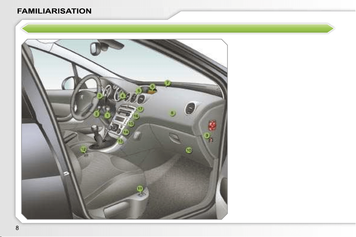
INSTRUMENTS AND CONTROLS
1.
Steering lock and ignition.
2.
Audio equipment steering wheel
control.
3.
Wipers/wash-wipe/trip computer
controls.
4.
Central adjustable and closing
vents.
5.
Fragrance diffuser.
6.
Multifunction display.
7.
Sunshine sensor.
8.
Passenger air bag.
9.
Passenger air bag disarming.
10.
Glove box/Audio/video sockets.
11.
Heated seat control.
12.
Lighter.
13.
Front ashtray.
14.
Heating/air conditioning controls.
15.
CD changer.
16.
Audio RD4 or RT4 GPS audio/
telephone.
17.
Alarm button.
Central locking button.
Hazard warning lights button.
Dynamic stability control (ESP/
ASR) button.
Parking assistance button.
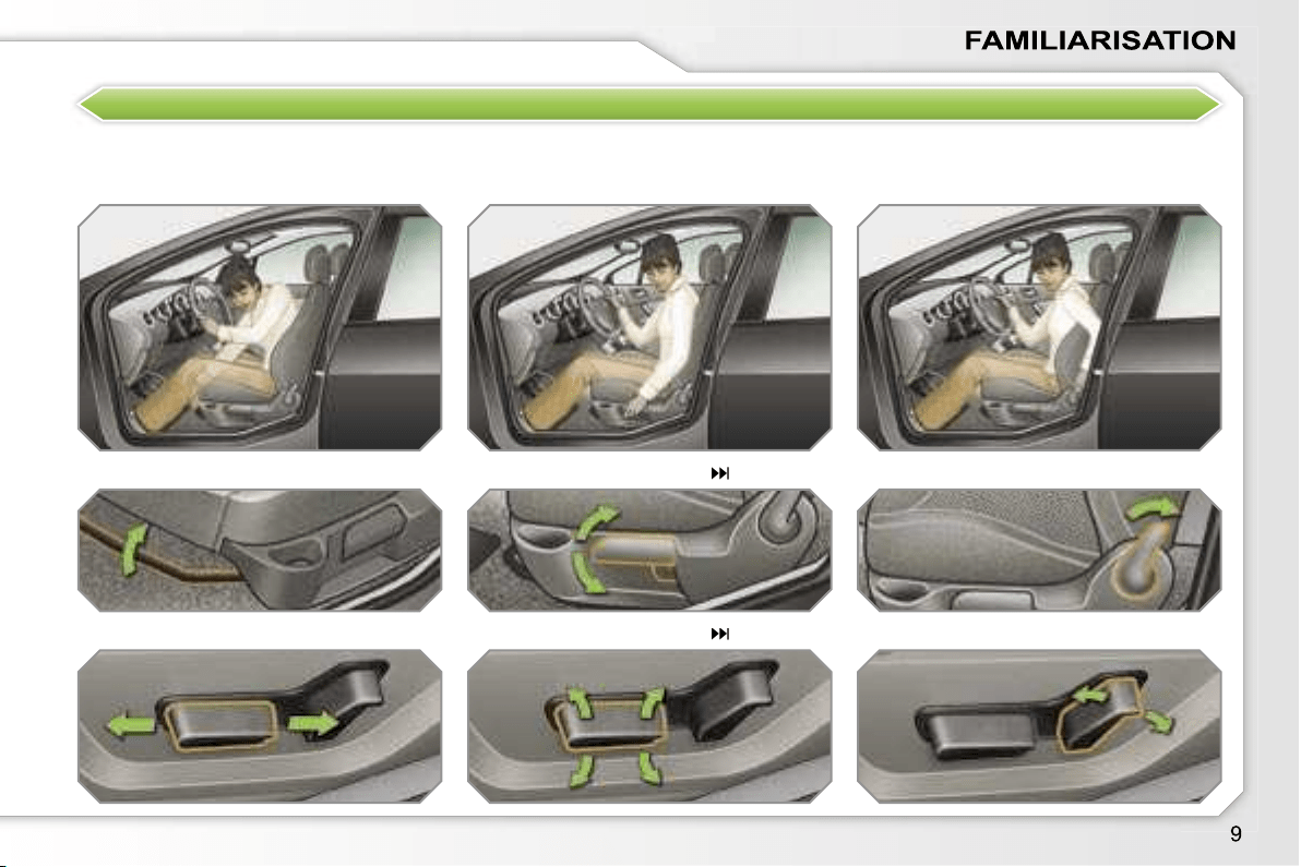
SIT COMFORTABLY
Driver’s seat adjustment
Manual
Electric
Forwards-backwards
54
55
Seat back angle
Height
i
Steering wheel adjustment
1.
Unlocking of the control.
2.
Adjustment of the height and
depth.
3.
Locking of the control.
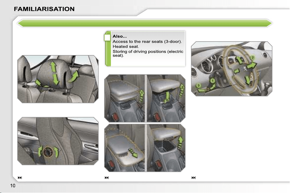
SIT COMFORTABLY
Front seat manual and
additional adjustments
Head restraint height and angle
Lumbar
Front armrest
56
90
62

i
Steering wheel adjustment
1.
Unlocking of the control.
2.
Adjustment of the height and
depth.
3.
Locking of the control.
SIT COMFORTABLY
Front seat manual and
additional adjustments
Head restraint height and angle
Lumbar
Front armrest
56
90
62
i
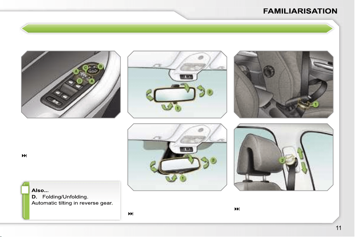
SIT COMFORTABLY
Exterior mirror adjustment
A.
Selection of the mirror.
B.
Adjustment of the position of the
mirror.
C.
De-selection of the mirror.
60
Interior mirror adjustment
1.
Selection of the "day" position of
the mirror.
2.
Directing of the mirror.
61
Front seat belt
1.
Fastening.
2.
Height adjustment.
108
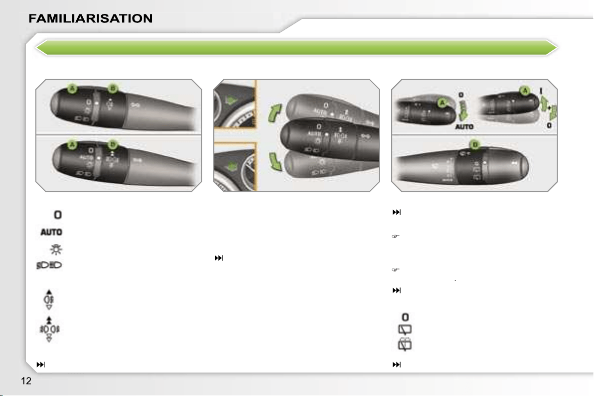
SEE CLEARLY
Lighting
Ring A
Ring B
"Motorway" function
Press up or down once, without passing
the point of resistance; the correspond-
ing direction indicators will flash three
times.
104
Direction indicators
Switching on "AUTO"
Press the lever down and release it.
Ring B: rear wiper
77
83
Lights off.
Automatic switching on of the
lights.
Side lights.
Dipped/main beam headlamps.
Rear fog lamp.
or
Front and rear fog lamps.
Park.
Intermittent wipe.
Wash-wipe.
Lever A: windscreen wipers
82
Wipers
Switching off "AUTO"
Push the lever up and return it to
position
"0"
.
84
–
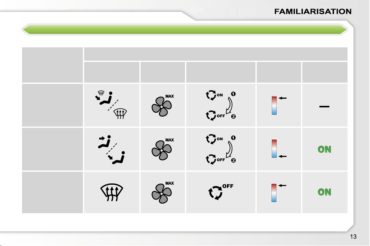
VENTILATION
Recommended interior settings
I require...
Heating or Manual Air Conditioning
Air distribution
Air flow
Air recirculation/Intake
of outside air
Temperature
Manual A/C
HOT
COLD
DEMISTING
DE-ICING
Automatic air conditioning:
we recommend use of the fully automatic mode by pressing the
"AUTO"
button.
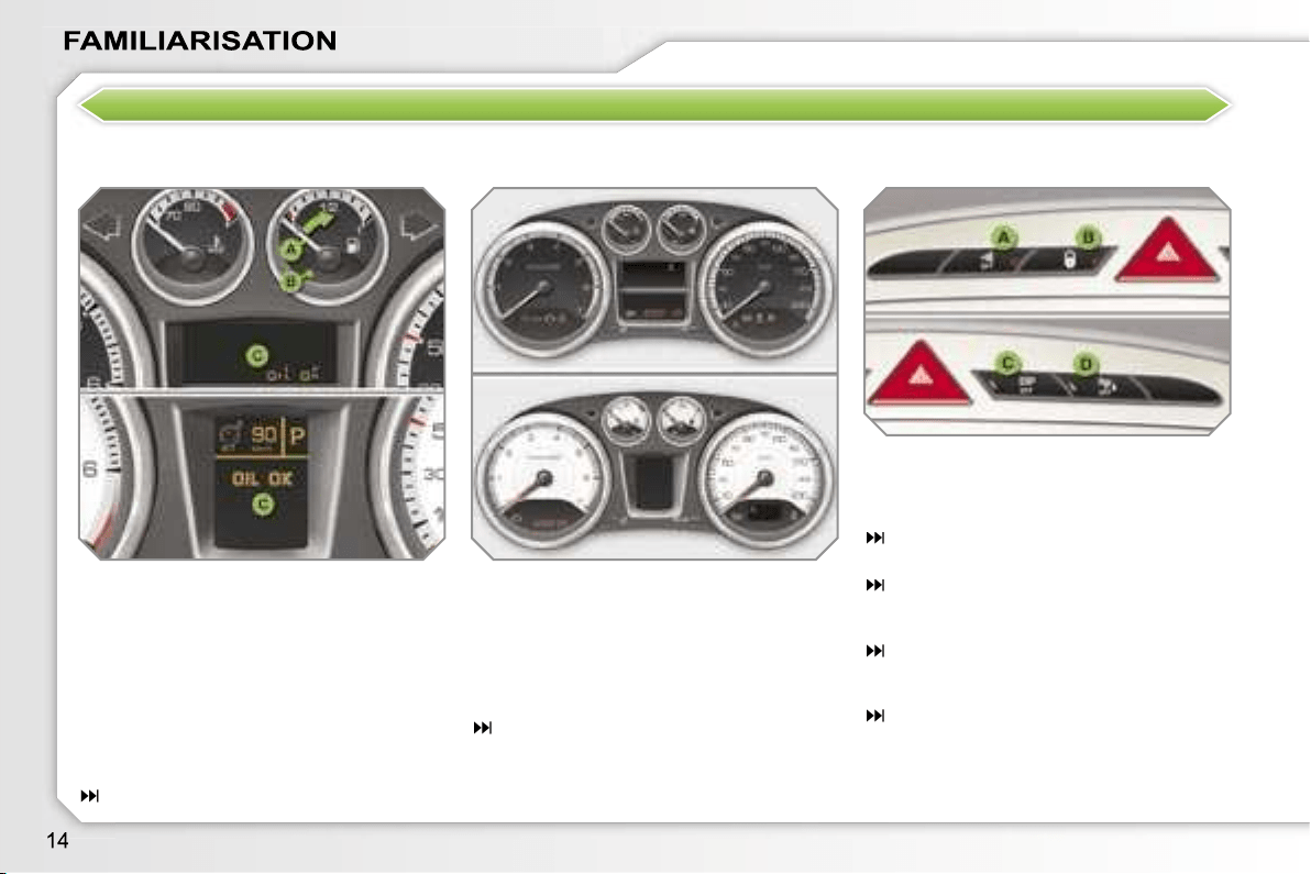
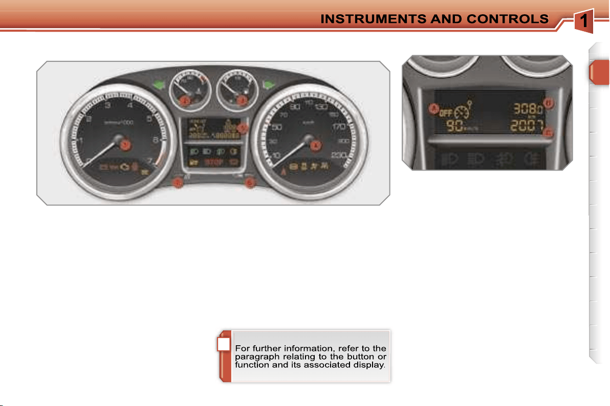
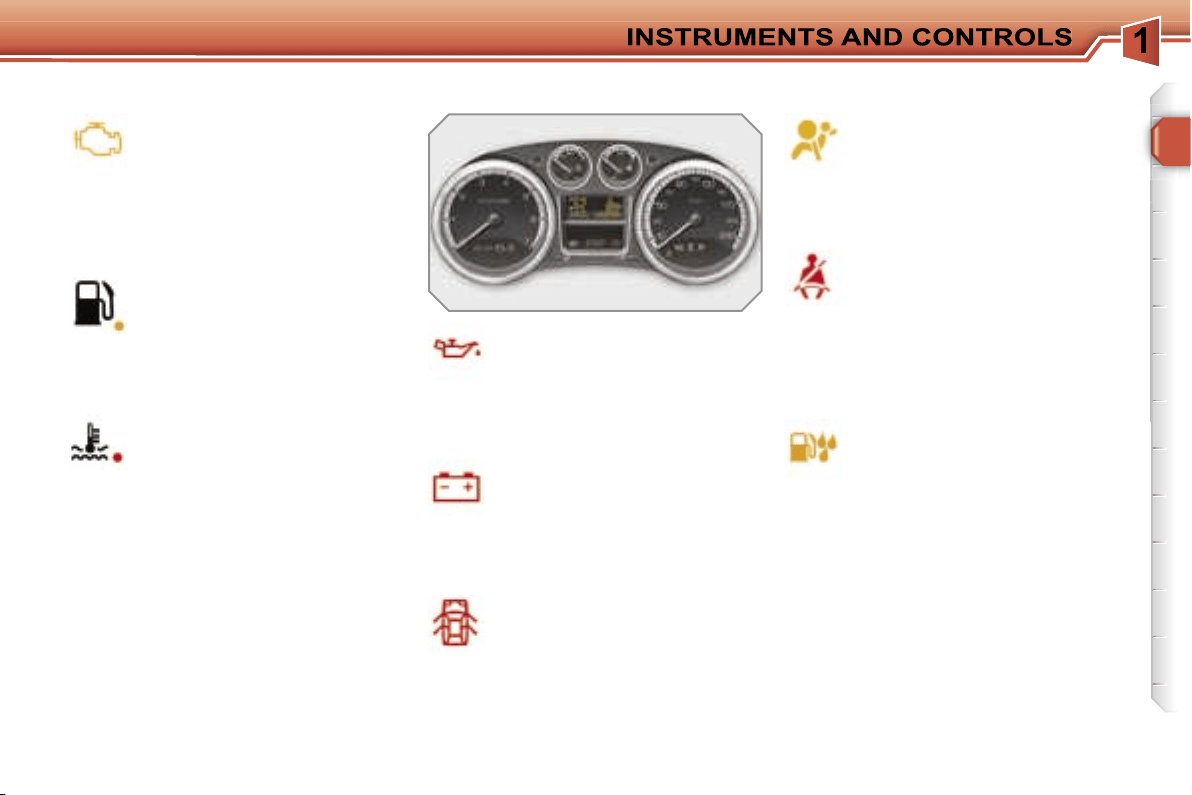
MONITOR THOROUGHLY
Instrument panel
Controls bar
A.
With the ignition on, the needle
should indicate the level of fuel
remaining.
B.
With the engine running, its
associated low level warning light
should switch off.
C.
With the ignition on, the oil level
indicator should display
"OIL OK"
for a few seconds.
If the levels are not correct, top up the
levels which are low.
17
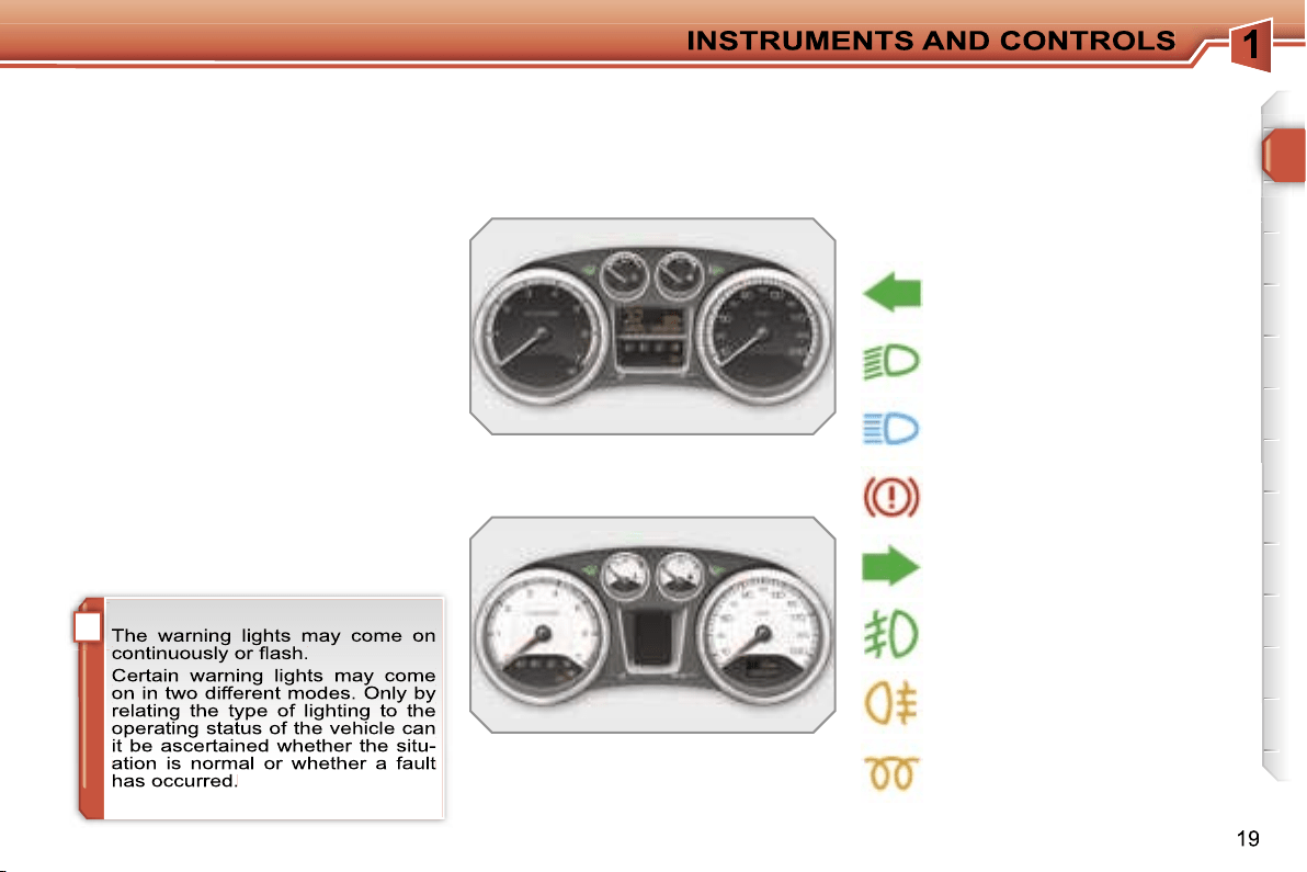
Lighting of the indicator light indicates
the status of the corresponding function.
A.
Disarming of the interior protection
alarm.
68
B.
Central locking.
73
C.
Deactivation of the ESP/ASR
system.
107
D.
Deactivation of the visual and
audible parking assistance.
128
1.
With the ignition on, the orange
and red warning lights come on.
2.
With the engine running, these
warning lights should switch off.
If warning lights remain on, refer to the
page concerned.
19
Warning lights
KEEP YOUR PASSENGERS SAFE
Passenger’s front air bag
Electric child lock
1.
Insertion of the key.
2.
Selection of the position:
"OFF"
(disarming), with "rear
facing" child seat,
"ON"
(activation), with front
passenger or "forwards facing"
child seat.
3.
Removal of the key keeping the
switch in this position.
111
Lighting of the indicator light indicates
the status of the corresponding function.
A.
Activation of the electric child lock.
103
A.
Front and/or rear seat belts not
fastened/unfastened warning light.
B.
Front left seat belt warning light.
C.
Front right seat belt warning light.
D.
Rear right seat belt warning light.
E.
Rear centre seat belt warning light.
F.
Rear left seat belt warning light.
G.
Passenger’s front air bag disarmed
warning light.
H.
Passenger’s front air bag activated
warning light.
108, 112
Seat belts and passenger’s front
air bag
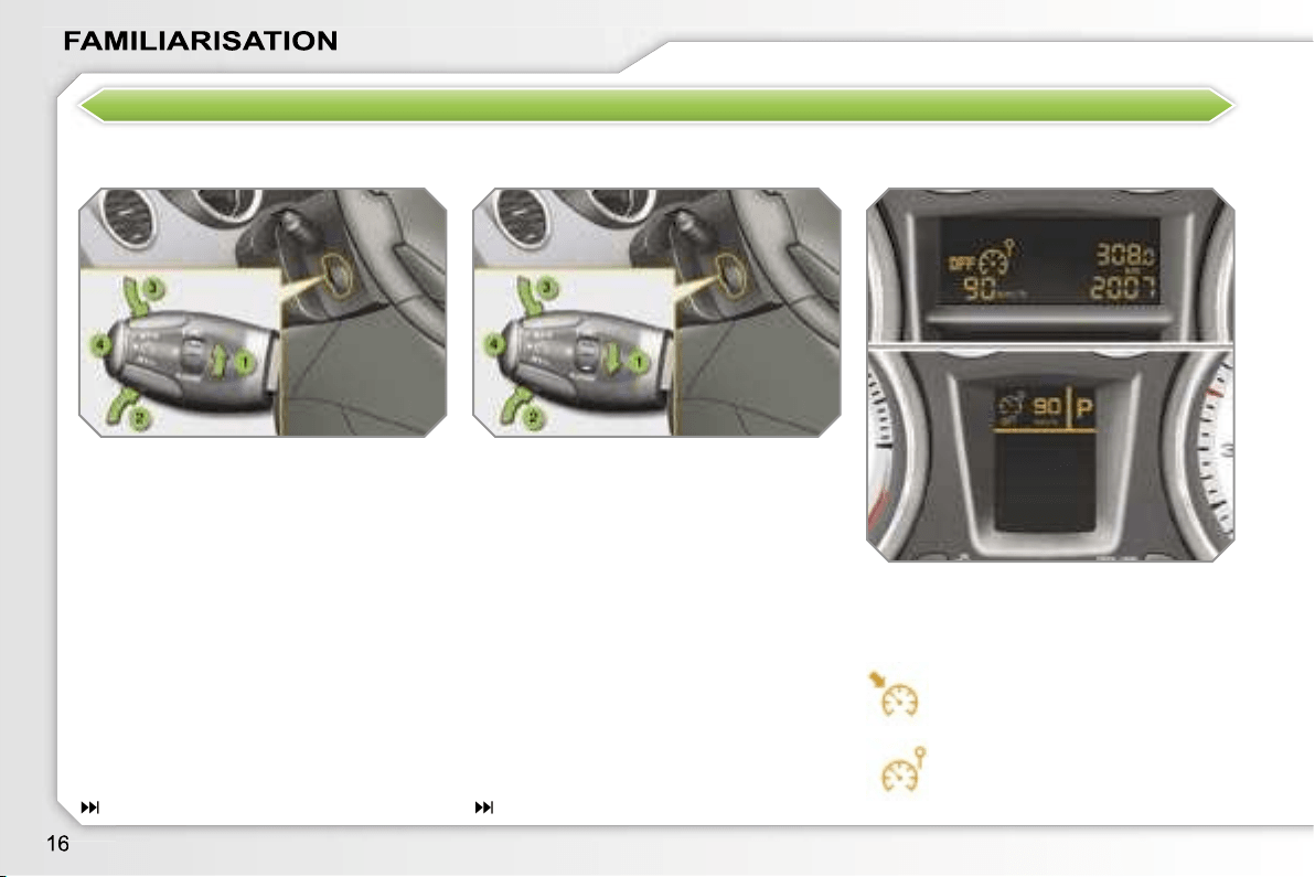
DRIVE SAFELY
Speed limiter "LIMIT"
Display on the instrument panel
1.
Limiter mode Selection/Off.
2.
Decreasing of the programmed
value.
3.
Increasing of the programmed
value.
4.
Speed limiter On/Off.
The values must be set with the engine
running.
The cruise control or speed limiter mode
appears on the instrument panel when
it is selected.
1.
Cruise control mode Selection/Off.
2.
Programming a speed/Decreasing
of the programmed value.
3.
Programming a speed/Increasing
of the programmed value.
4.
Cruise control Off/Resume.
In order to be programmed or activated,
the vehicle speed must be higher than
25 mph (40 km/h), with at least fourth
gear engaged on the manual gearbox
(second gear for the 6-speed piloted
manual or automatic gearbox).
Cruise control "CRUISE"
Cruise control
Speed limiter
125
123
i
17
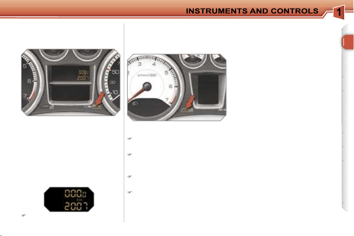
PETROL - DIESEL MANUAL GEARBOX INSTRUMENT PANELS
Panel grouping together the vehicle
operation indication dials and warning
lights.
5.
Display.
6.
Display zero reset button.
Resets the selected function to
zero (trip distance recorder or
service indicator).
7.
Instrument panel lighting
button.
Adjusts the brightness of the
lighting of the instruments and
controls.
Dials
1.
Rev counter.
Indicates the speed of rotation of
the engine (x 1 000 rpm).
2.
Coolant temperature.
Indicates the temperature of the
engine coolant (°Celsius).
3.
Fuel level.
Indicates the quantity of fuel
remaining in the tank.
4.
Vehicle speed.
Indicates the current speed of the
moving vehicle (km/h or mph).
A.
Speed limiter
or
Cruise control.
(km/h or mph)
B.
Trip distance recorder.
(km or miles)
Display
The following three functions are dis-
played in succession when the ignition
is switched on.
C.
Service indicator.
(km or miles) then,
Engine oil level indicator.
then
Distance recorder.
(km or miles)
i
18
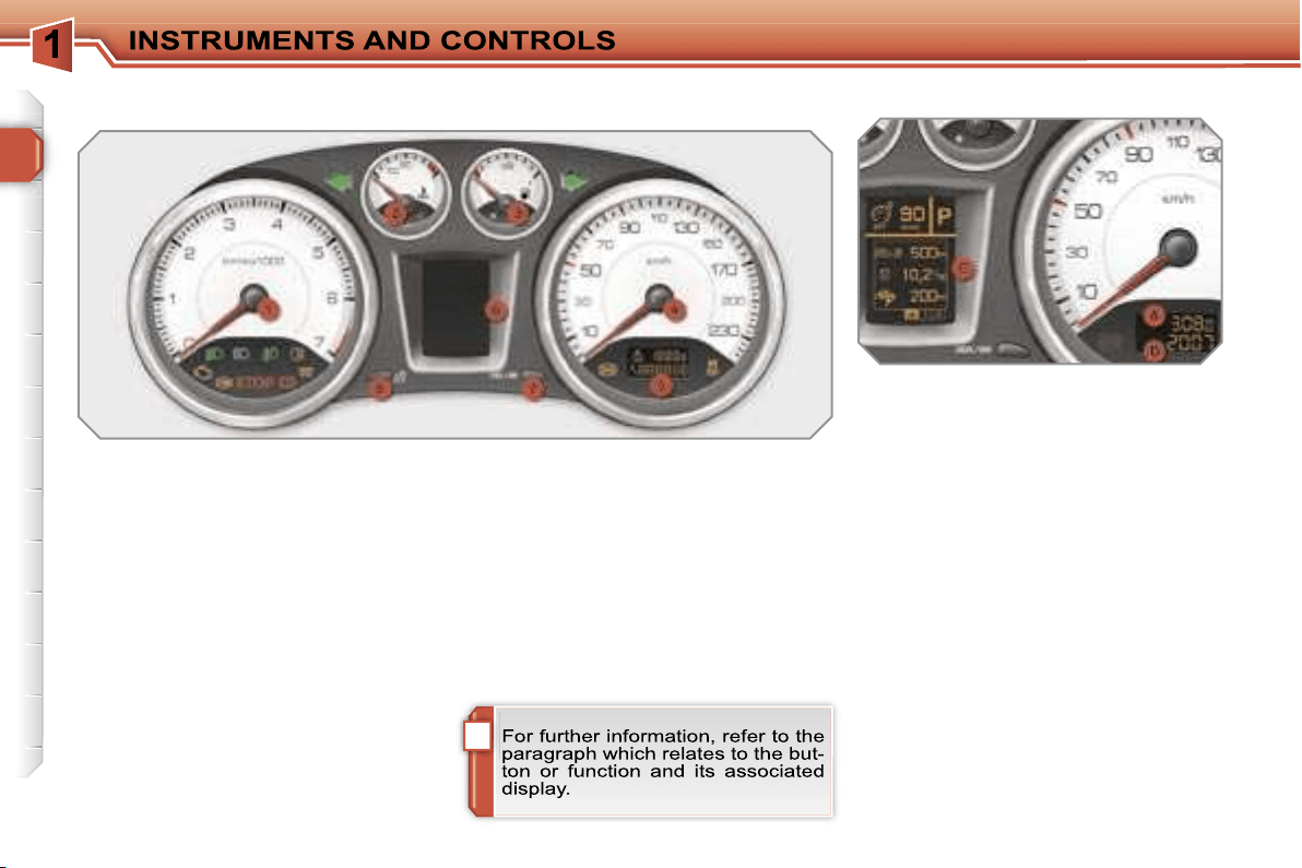
PETROL - DIESEL MANUAL OR 6-SPEED PILOTED MANUAL OR
AUTOMATIC GEARBOX INSTRUMENT PANELS
Panel grouping together the vehicle
operation indication dials and warning
lights.
5.
Small display.
6.
Large display.
7.
CHECK/display zero reset
button.
Starts a manual CHECK.
Resets the function selected to
zero (trip distance recorder or
service indicator).
8.
Instrument panel lighting
button.
Adjusts the brightness of the lighting
of the instruments and controls.
Dials
1.
Rev counter.
Indicates the speed of rotation of
the engine (x 1 000 rpm).
2.
Coolant temperature.
Indicates the temperature of the
engine coolant (°Celsius).
3.
Fuel level.
Indicates the quantity of fuel
remaining in the tank.
4.
Vehicle speed.
Indicates the current speed of the
moving vehicle (km/h or mph).
A.
Trip distance recorder.
(km or miles)
B. Distance recorder.
(km or miles)
Displays
The following two functions are dis-
played in succession when the ignition
is switched on.
C.
Service indicator.
(km or miles) then,
Engine oil level indicator.
The following functions are displayed in
accordance with the selection.
- Warning lights/CHECK.
- Tyre under-inflation detection.
- Speed limiter/Cruise control.
- 6-speed piloted manual or automat-
ic gearbox.
- Navigation - Guidance/Trip compu-
ter information.
!
Indicator and warning lights
Visual indicators informing the driver
that a system is in operation (operation
or deactivation indicator lights) or of the
occurrence of a fault (warning light).
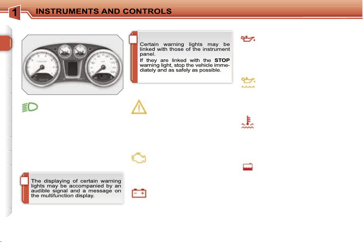
Associated warnings
The switching on of certain warning
lights may be accompanied by an audi-
ble signal and a message on the multi-
function display.
Operation indicator lights
If one of the following indicator lights comes
on, this confirms that the corresponding
system has come into operation.
Left-hand direction
indicator.
Handbrake
applied.
Right-hand direction
indicator.
Main beam headlamps.
Dipped headlamps.
Diesel engine pre-heating.
Wait until this is switched off be-
fore operating the starter.
Front fog lamps.
Rear fog lamp.
When the ignition is switched on
The warning lights come on for a few
seconds when the vehicle’s ignition is
switched on.
When the engine is started, these warn-
ing lights should switch off.
If they remain on, before moving off,
consult the warning light concerned.
Common operation indicator lights
20
Foot on brake.
Press the brake pedal to start
the engine with the 6-speed pi-
loted manual gearbox or auto-
matic gearbox.
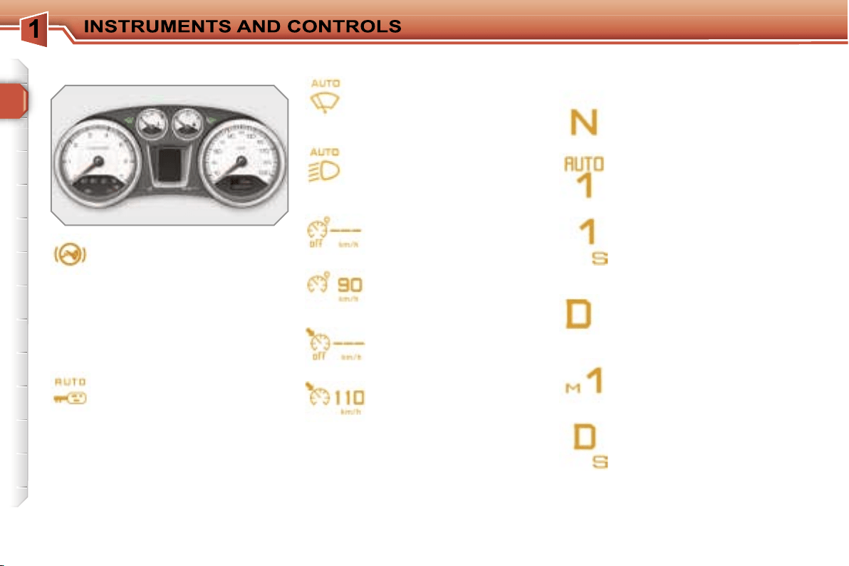
Specific operation indicator lights
The other indicator lights appear on the
large display, located in the centre of
the instrument panel.
Automatic locking.
If this is displayed, it indicates
that you have activated the au-
tomatic locking of the doors and
boot while driving.
Speed limiter.
If this is displayed, it indi-
cates that you have activat-
ed the speed limiter mode.
If this is displayed, it indi-
cates that you can set the
speed limiter speed value to
be stored.
Cruise control.
If this is displayed, it indi-
cates that you have activat-
ed the cruise control mode.
If this is displayed it indi-
cates that you can set the
cruise control speed value
to be stored.
Automatic gearbox.
This display indicates the posi-
tion that you have selected on
the gear selection gate (P, R, N
or D).
6-speed piloted manual gearbox.
This display indicates the po-
sition that you have selected
on the gear selection gate (R,
N, A or M).
Automatic wiping.
If this is displayed, it indicates
that you have activated the au-
tomatic windscreen wiping.
Automatic lighting.
If this is displayed, it indicates
that you have activated the
automatic switching on of the
headlamps.
This display indicates the gear
engaged in automatic or man-
ual operating mode (1 to 6).
This display indicates the op-
erating mode selected (auto-
matic or sport).
This display indicates the
gear engaged in the automat-
ic or manual operation pro-
gramme.
This display indicates the op-
erating programme selected
(automatic, sport, snow or
manual).
21
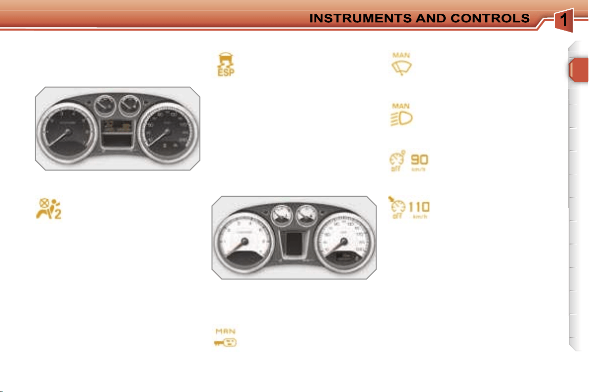
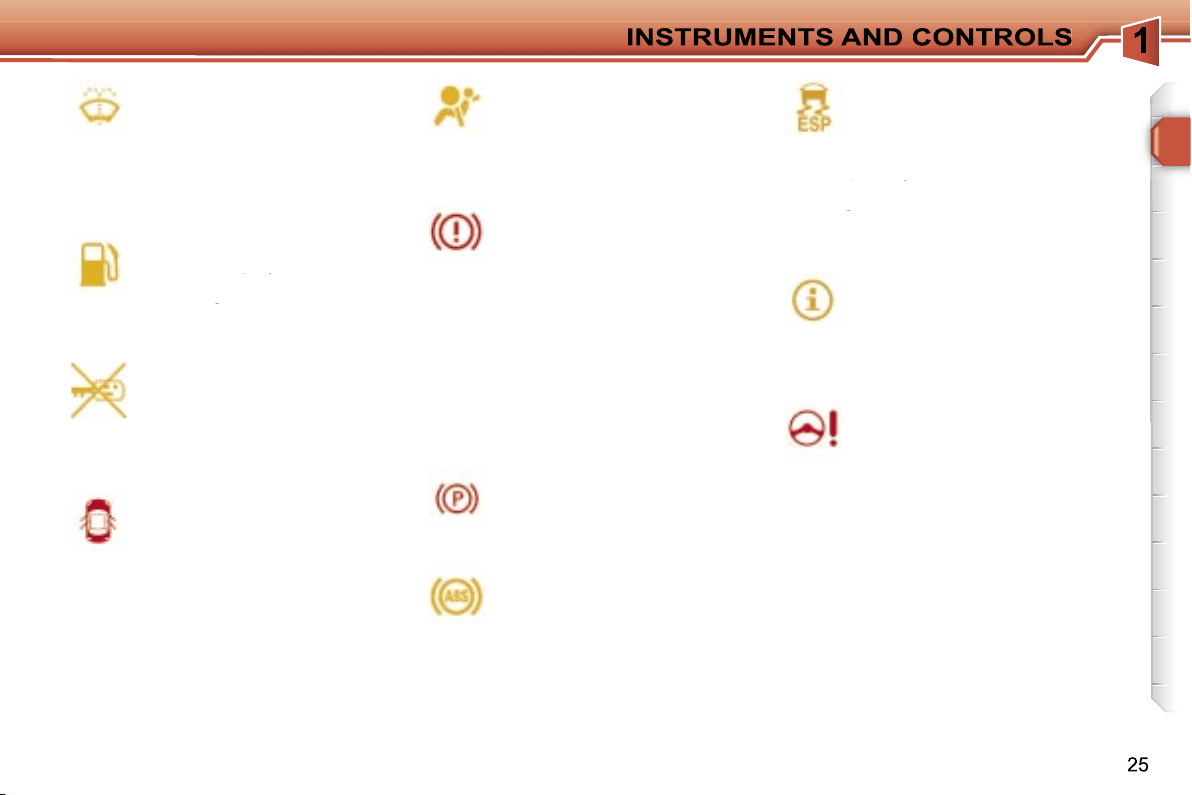
Deactivation warning lights
If one of the following warning lights
comes on, this confirms that the corre-
sponding system has been switched off
intentionally.
Passenger’s air bag system
deactivation.
The passenger’s air bag system
is put into service automatically
when the vehicle is started.
A specific control, located on
the passenger’s side of the fascia, per-
mits deactivation of the system. This is
confirmed by continuous lighting of this
warning light on the instrument panel or
on the seat belt and passenger’s front
air bag warning lights display.
Dynamic stability control
(ESP/ASR) deactivation.
The ESP/ASR system is put
into service automatically when
the vehicle is started.
A specific button, located in the centre
of the fascia, permits deactivation of the
system. This is confirmed by continu-
ous lighting of this warning light and of
the indicator light on the button.
Common deactivation warning
lights
Specific deactivation warning lights
Automatic locking.
If this is displayed, it indicates
that you have deactivated the
automatic locking of the doors
and boot while driving.
Automatic wiping.
If this is displayed, it indicates
that you have deactivated the
automatic windscreen wiping.
The other warning lights appear on the
large display, located in the centre of
the instrument panel.
Speed limiter.
If this is displayed, it indi-
cates that you have deacti-
vated the speed limiter.
Cruise control.
If this is displayed, it indi-
cates that you have deacti-
vated the cruise control.
Automatic lighting.
If this is displayed, it indicates
that you have deactivated the
automatic switching on of the
headlamps.
!
22
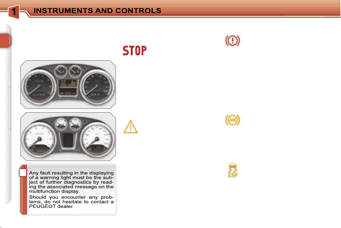
When the engine is running or the vehi-
cle is moving, the lighting of one of the
following warning lights indicates the
occurrence of a fault requiring interven-
tion on the part of the driver.
Central alert.
Lighting is associated with
the displaying of another
warning light:
- punctured wheel,
- braking,
- power steering,
- engine oil pressure,
- coolant temperature,
stop the vehicle immediately and as
safely as possible.
Service.
If this comes on, it indicates the
occurrence of a problem in one
of the systems which does not
have a specific warning light.
In order to identify it, consult the mes-
sage on the multifunction display.
After checking:
- that the doors, boot and bonnet are
closed,
- the engine oil level,
- the screenwash fluid level,
- the remote control battery,
- the pressure of the tyres,
- the end of saturation of the particle
emission filter (Diesel),
for any other situations, contact a
PEUGEOT dealer.
Braking.
If this comes on, it indicates the
occurrence of a fault in one of
the braking systems:
- significant drop in the level in the cir-
cuit,
- electronic brake force distribution
(EBFD) faulty (simultaneous lighting
of the ABS warning light),
stop the vehicle immediately and as
safely as possible.
When the vehicle is moving, check that
the handbrake is fully released.
Warning lights
Anti-lock braking system
(ABS).
If this comes on, it indicates the
occurrence of a fault in the anti-
lock braking system.
However, this does not prevent opera-
tion of the vehicle’s assisted braking.
Common warning lights
Dynamic stability control
(ESP/ASR).
The ESP/ASR system is put
into service automatically when
the vehicle is started.
Unless the system has been deactivat-
ed, if this warning light and the indica-
tor light on the button come on continu-
ously, this indicates the occurrence of a
fault in the ESP/ASR system or in the
hill start assistance.
23
Engine autodiagnostics
system.
If this comes on, it indicates the
occurrence of a fault in the en-
gine management system.
If it flashes, it indicates the occurrence
of a fault in the emission control sys-
tem.
Low fuel level.
If this comes on, it indicates that
you only have enough fuel left
to drive approximately 30 miles
(50 km).
The capacity of the tank is approximate-
ly 60 litres.
Maximum coolant
temperature.
If this comes on, it indicates that
the temperature in the cooling
system is too high. Stop the vehicle im-
mediately and as safely as possible.
Air bags.
If this comes on, it indicates the
occurrence of a fault in one of
the air bag or seat belt preten-
sioner systems.
Seat belt not fastened/
unfastened.
If this comes on, it indicates
that the driver and/or the front
passenger has not fastened or has un-
fastened his seat belt.
It also indicates that one or more rear
passengers have unfastened their seat
belt.
Water in diesel.
If this comes on, it indicates the
presence of water in the diesel
filter.
There is a risk of damage to the
injection system on Diesel engines.
Door open.
A door, the boot or the bonnet*
is open:
- if the speed is below 6 mph (10 km/h),
this warning light comes on continuously.
-
if the speed is higher than 6 mph (10 km/h),
this warning light comes on continuously,
accompanied by an audible signal.
Battery charge.
If this comes on, it indicates
the occurrence of a fault in the
battery charging circuit (dirty or
loose terminals, slack or cut alternator
belt, ...).
Engine oil pressure.
If this comes on, it indicates the
occurrence of a fault in the en-
gine lubrication circuit. Stop the
vehicle immediately and as safely as
possible.
Specific warning lights
* Only with alarm.
i
!
24
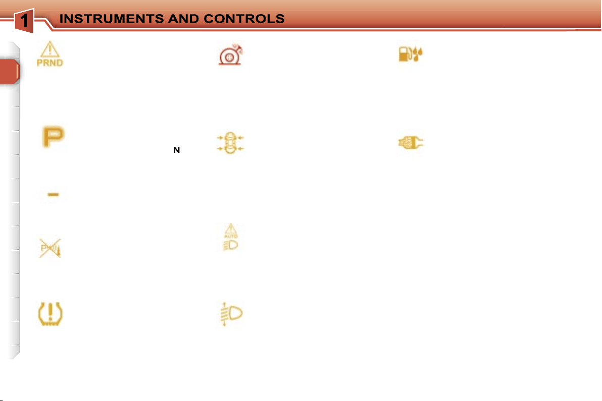
Specific warning lights
The other warning lights appear on the
large display, located in the centre of
the instrument panel.
Depending on the seriousness of the
fault, they may be displayed in orange
or red.
Directional headlamps.
If this flashes, it indicates the
occurrence of a fault in the di-
rectional headlamps system.
Engine oil pressure.
If this is displayed, it indicates
the occurrence of a fault in the
engine lubrication circuit. Stop
the vehicle immediately and as safely
as possible.
Service.
If this is displayed, it indicates
the occurrence of a fault in one
of the following:
- the engine management system,
- the emission control system,
- the lane departure warning system.
Engine autodiagnostics
system.
If this is displayed, it indicates
the occurrence of a fault in the
engine management system.
Engine oil level.
If this is displayed, it indicates
an insufficient level of oil in the
engine. Stop the vehicle imme-
diately and as safely as possible.
Coolant temperature.
If this is displayed, it indicates
that the temperature in the
cooling system is too high. Stop
the vehicle immediately and as safely
as possible.
Coolant level.
If this is displayed, it indicates
an insufficient level of coolant in
the circuit. Stop the vehicle im-
mediately and as safely as possible.
Battery charge.
If this is displayed, it indicates
the occurrence of a fault in the
battery charging circuit (dirty or
loose terminals, slack or cut alternator
belt, ...).
Air bags.
If this is displayed, it indicates
the occurrence of a fault in one
of the air bag or pretensioning
seat belt systems.
Braking.
If this is displayed, it indicates
the occurrence of a fault in one
of the braking systems:
- significant drop in the level in the cir-
cuit,
- electronic brake force distribution
(EBFD) faulty (simultaneous lighting
of the ABS warning light).
Stop the vehicle immediately and as
safely as possible.
If the vehicle is moving, check that the
handbrake is released fully.
Anti-lock braking system
(ABS).
If this is displayed, it indicates
the occurrence of a fault in the
anti-lock braking system.
However, this does not prevent opera-
tion of the vehicle’s assisted braking.
Dynamic stability control
(ESP/ASR).
The ESP/ASR system is put
into service automatically when
the vehicle is started.
Unless the system has been deacti-
vated, if this warning light and the indi-
Unless the system has been deacti-
Unless the system has been deacti-
cator light on the button come on, this
indicates the occurrence of a fault in the
cator light on the button come on, this
cator light on the button come on, this
ESP/ASR system or in the hill start as-
sistance.
Power steering.
If this is displayed, it indicates
the occurrence of a fault in the
power steerin. Stop the vehicle
immediately and as safely as possible.
Door open.
A door, the boot or the bonnet*
is open:
- if the speed is below 6 mph (10 km/h),
this warning light is displayed in or-
ange,
-
if the speed is higher than 6 mph (10 km/h),
this warning light is displayed in red.
Ice warning.
If this is displayed, it indicates
that there is risk of the forma-
tion of ice on the road below a
temperature of 3 °C.
Drive carefully.
Handbrake.
If this is displayed, while the ve-
hicle is moving, it indicates that
the handbrake has not been re-
leased fully.
Electronic immobiliser.
If this is displayed, it indicates
the occurrence of a fault in the
electronic engine immobiliser
system or that the remote control bat-
tery is flat.
* Only with alarm.
Fuel level.
If this is displayed, it indicates
that there is only enough fuel
If this is displayed, it indicates
If this is displayed, it indicates
remaining to drive approximate-
ly 30 miles (50 km).
remaining to drive approximate-
remaining to drive approximate-
The capacity of the tank is approximate-
ly 60 litres.
Screenwash fluid level.
If this is displayed, following an
action on the wipers stalk, it in-
dicates an insufficient level of
fluid.
Fill the screenwash/headlamp wash flu-
id reservoir when you stop.
26
Water in diesel.
If this is displayed, it indicates
the presence of water in the
diesel filter.
There is a risk of damage to the injec-
tion system on Diesel engines.
Automatic headlamp
adjustment.
If this is displayed, it indicates
the occurrence of a fault in the
automatic headlamp adjust-
ment.
Particle emission filter
(Diesel).
If this is displayed, linked with
the service warning light, it indi-
cates the start of saturation of the parti-
cle emission filter or a low diesel additive
reservoir level.
As soon as traffic conditions permit, re-
generate the filter by driving at a speed
of at least 40 mph (60 km/h) until the
service warning light is switched off.
If the service warning light is still dis-
played, the additive level is low. Have it
topped up by a PEUGEOT dealer with-
out delay.
Deflated wheel.
If this is displayed, it indicates
an insufficient pressure in one
or more wheels.
Check the pressure of the tyres as soon
as possible.
Punctured wheel.
If this is displayed, it indicates
that one or more wheels are
punctured. Stop the vehicle im-
mediately and as safely as possible.
Change the damaged wheel and have it
repaired by a PEUGEOT dealer.
Tyre under-inflation
detection.
If this is displayed, it indicates
the occurrence of a fault on one
of the sensors or in the tyre under-infla-
tion detection system.
It may also indicate the absence of a
sensor when the spare wheel, which
does not have a sensor, is fitted in place
of a puntured wheel.
Automatic switching on of
the lights.
If this comes on, it indicates the
occurrence of a fault in the au-
tomatic switching on of the lights.
Use the other positions of the lights
stalk.
Visual and/or audible
parking assistance.
If this comes on, in forward and/
or reverse gear, it indicates a
fault in the parking assistance system.
6-speed piloted manual
gearbox or automatic
gearbox.
If this is displayed, it indicates
the occurrence of a fault in the 6-speed
piloted manual gearbox or automatic
gearbox. The gearbox will then oper-
ate in down-grade mode, locked on 3rd
gear.
Invalid value.
If this is displayed, it indicates
the occurrence of a fault in the
programme of the 6-speed pi-
loted manual gearbox or auto-
matic gearbox.
Position P or N.
If this is displayed, it indicates
that the gear lever must be
placed in position
P
or
N
in or-
der to start the engine.
27
Coolant temperature indicator
System which informs the driver of the
changes in the temperature of the en-
gine coolant while driving.
With the engine running, when the nee-
dle is:
- in zone
A
, the temperature is correct,
- in zone
B
, the temperature is too high;
the max temperature warning light
1
and the central
STOP
warning light
come on, accompanied by an audible
signal and a message on the multi-
function display.
You MUST stop as soon as it is safe
to do so.
Wait a few minutes before switching off
the engine.
Contact a PEUGEOT dealer.
After driving for a few minutes, the tem-
perature and pressure in the cooling
system increase.
To top up the level:
wait for the engine to cool,
unscrew the cap by two turns to al-
low the pressure to drop,
when the pressure has dropped, re-
move the cap,
top up the level to the "MAX" mark.
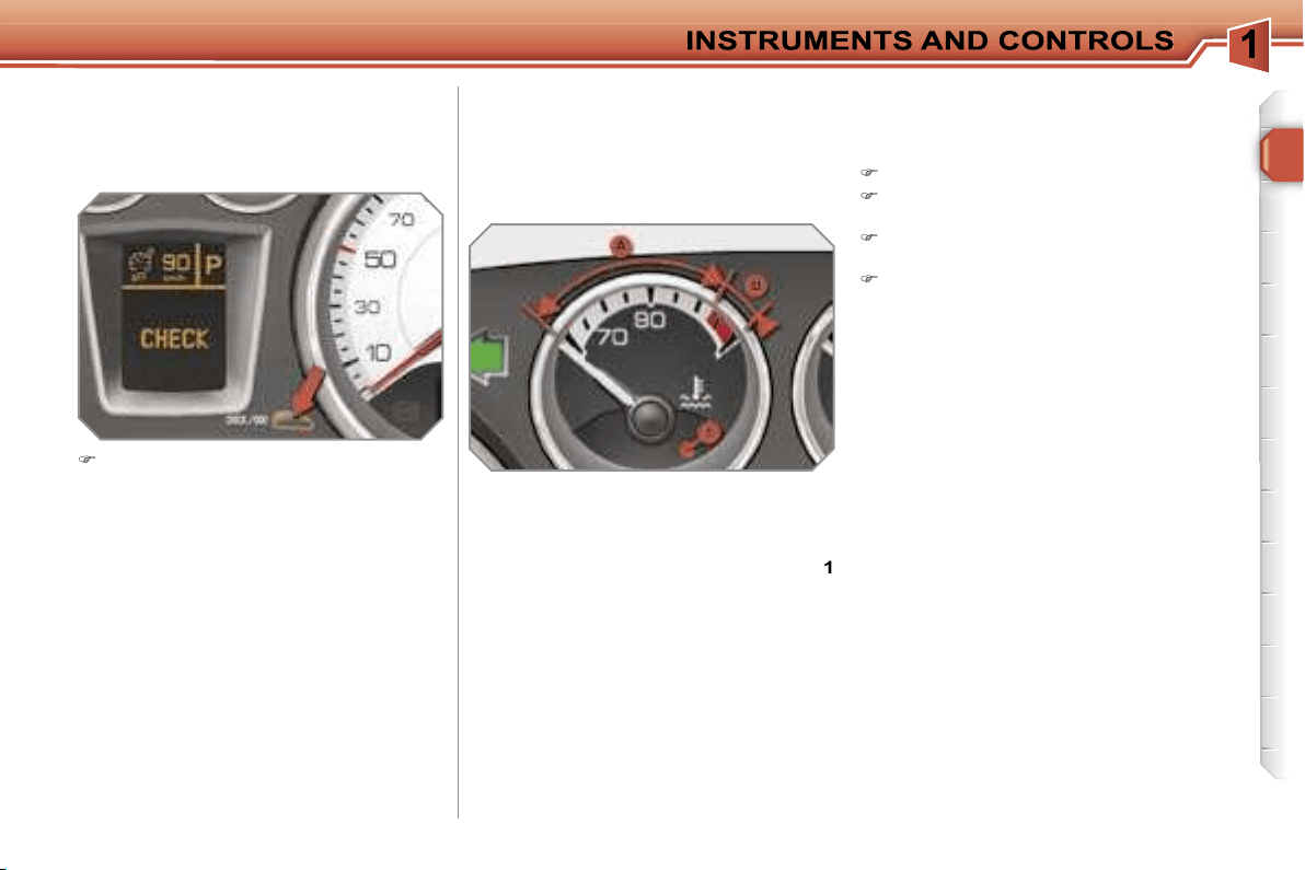
Manual CHECK
System which informs the driver of the
warnings present and of the activated
or deactivated status of the functions.
With the engine running, to start a
manual check, press the
"CHECK/
000"
button on the instrument panel.
If no "major" faults have been detected,
"CHECK OK"
appears on the large in-
strument panel display.
If a "minor" fault has been detected, the
warning lights concerned then
"CHECK
OK"
appear on the large instrument
panel display. Contact a PEUGEOT
dealer as soon as possible.
If a "major" fault has been detected, only
the warning lights concerned appear on
the large instrument panel display. Con-
tact a PEUGEOT dealer without delay.
28
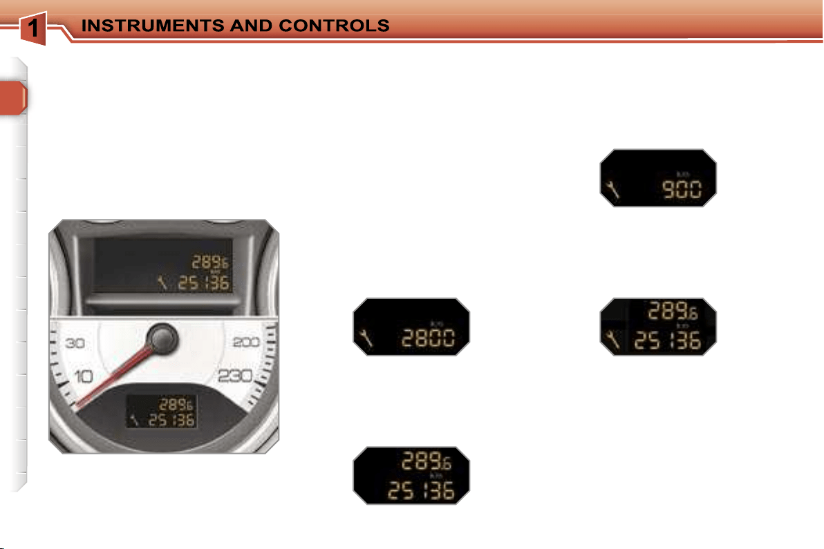
Service indicator
System which informs the driver when
the next service is due, in accord-
ance with the manufacturer’s servicing
schedule.
The point at which the service is due is
calculated from the last indicator zero re-
set. It is determined by two parameters:
- the distance travelled,
- the time elapsed since the last service.
Between 600 miles (1 000 km) and
1 800 miles (3 000 km) remain before
the next service is due
For 5 seconds after the ignition is
switched on, the spanner symbolising
the service operations comes on. The
distance recorder display line indicates
the distance remaining before the next
service is due.
Example:
2 800 km remain before the
next service is due.
For 5 seconds after the ignition is
switched on, the display indicates:
5 seconds after the ignition is switched
on,
the spanner is switched off
; the
distance recorder resumes its normal
operation. The display then indicates
the total and trip distances.
Less than 600 miles (1 000 km)
remain before the next service is due
Example:
900 km remain before the
next service is due.
For 5 seconds after the ignition is
switched on, the display indicates:
5 seconds after the ignition is switched
on, the distance recorder resumes its
normal operation.
The spanner re-
mains on
to indicate that a service
must be carried out soon.
More than 1 800 miles (3 000 km)
remain before the next service is due
When the ignition is switched on, no
service information appears on the dis-
play.
i
i
29
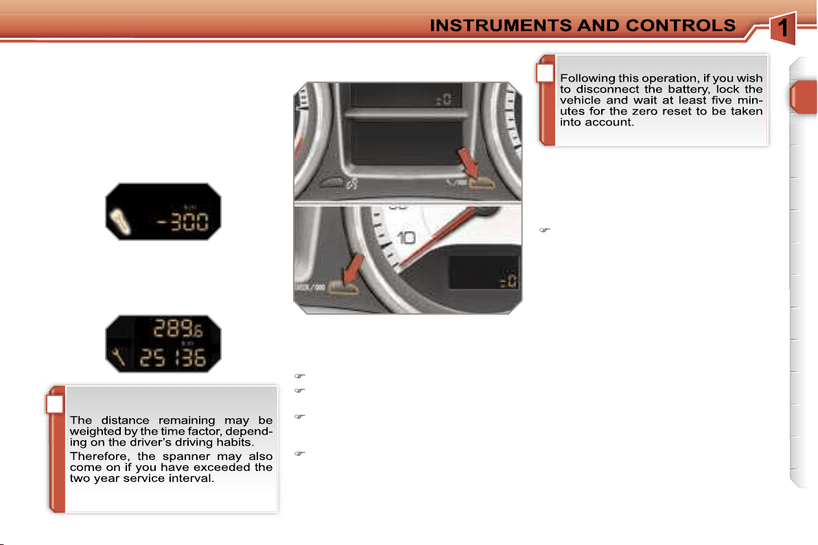
Service indicator zero reset
After each service, the service indicator
must be reset to zero.
To do this, carry out the following pro-
cedure:
switch off the ignition,
press and hold the trip distance re-
corder zero reset button,
switch on the ignition; the distance
recorder display begins a count-
down,
when the display indicates
"=0"
, re-
lease the button; the spanner disap-
pears.
Service overdue
For 5 seconds after the ignition is
switched on,
the spanner flashes
to
indicate that the service must be carried
out as soon as possible.
Example:
the service is overdue by
300 miles (km).
For 5 seconds after the ignition is
switched on, the display indicates:
5 seconds after the ignition is swit-
ched on, the distance recorder resu-
mes its normal operation.
The spanner
remains lit.
Retrieving the service information
You can access the service information
at any time.
Press the trip distance recorder zero
reset button.
The service information is displayed
for a few seconds, then disappears.
i
30
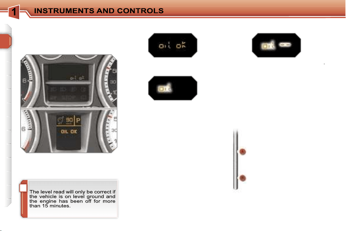
Engine oil level indicator
System which informs the driver of the
validity or invalidity of the engine oil
level.
This information is indicated for a few
seconds when the ignition is switched
on, after the service information.
Oil level correct
Lack of oil
Oil level gauge fault
Dipstick
This is indicated by the flashing of
"OIL"
,
linked with the service warning light, ac-
companied by an audible signal and a
message on the multifunction display.
If the lack of oil is confirmed by a check
using the dipstick, it is essential that the
level is topped up to prevent damage to
the engine.
This is indicated by the flashing of
"OIL --"
.
Contact a PEUGEOT dealer.
Refer to the "Checks" section to locate
the dipstick and the oil filler cap on your
engine.
There are 2 marks on the
dipstick:
-
A
= max; never exceed
this level,
-
B
= min; top up the level
via the oil filler cap, using
the type of oil suited to
your engine.
31
Total distance recorder
System which measures the total dis-
tance travelled by the vehicle during its
life.
Lighting rheostat
System for manual adjustment of the
brightness of the instruments and con-
trols in relation to the exterior bright-
ness.
The total and trip distances are dis-
played for thirty seconds when the ig-
nition is switched off, when the driver’s
door is opened and when the vehicle is
locked or unlocked.
Trip distance recorder
System which measures a distance
travelled during a day or other period
until it is reset to zero by the driver.
With the ignition on, press the button
until zeros appear.
Activation
When the lights are on:
press the button to change the
brightness of the instruments and
controls,
when the lighting reaches the mini-
mum setting, release the button,
then press again to increase it,
or
when the lighting reaches the maxi-
mum setting, release the button,
then press again to reduce it,
when the lighting reaches the level
of brightness required, release the
button.
Deactivation
When the lights are off, or in day mode
on vehicles fitted with daytime lights,
pressing the button does not have any
effect.

32
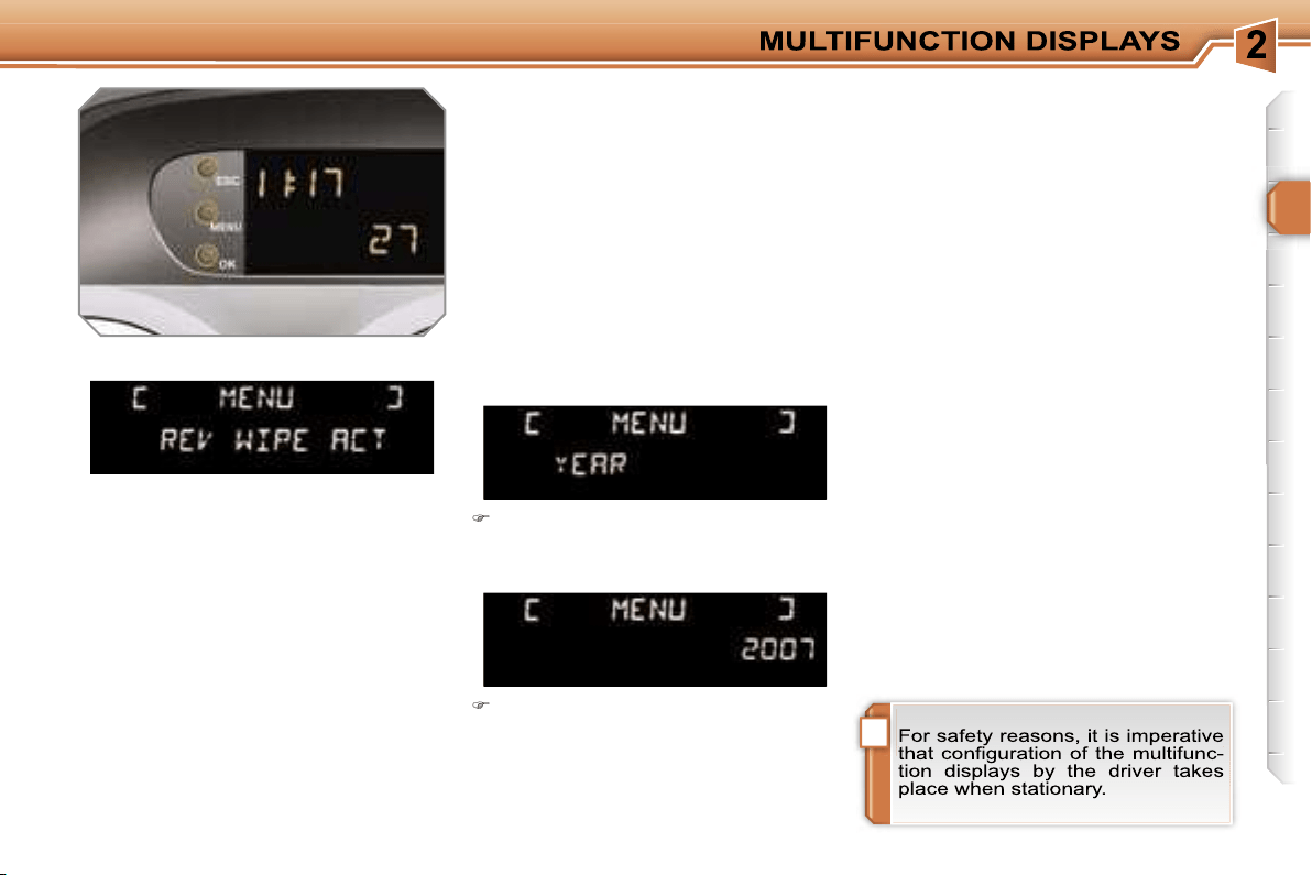
Displays on the screen
This displays the following information:
- the time,
- the date,
- the outside temperature* (this flashes
if there is a risk of ice),
- the status of the accesses (doors,
boot, ...),
- the trip computer (refer to the end of
the section).
Warning messages (e.g.: "Emission
control system faulty") or information
messages (e.g.: "Boot open") may ap-
pear temporarily. These can be cleared
by pressing the
"ESC"
button.
MONOCHROME SCREEN A
(without RD4 audio equipment)
Controls
General menu
There are three display control buttons:
-
"ESC"
to abandon the operation in
progress,
-
"MENU"
to scroll through the menus
or sub-menus,
-
"OK"
to select the menu or sub-menu
required.
Press the
"MENU"
button to scroll
through the various menus of the
general menu
:
- vehicle configuration,
- options,
- display settings,
- languages,
- units.
Press the
"OK"
button to select the
menu required.
* With air conditioning only.
!
33
Vehicle configuration
Options
Once the "Options" menu has been
selected, you can start diagnostics of
the status of the equipment (active, not
active, faulty).
Languages
Once the "Languages" menu has been
selected, you can change the language
used by the display (Français, Italiano,
Nederlands, Portugues, Portugues-
Brasil, Deutsch, English, Espanol).
Display settings
Once the "Display settings" menu has
been selected, you can gain access to
the following settings:
- year,
- month,
- day,
- hour,
- minutes,
- 12 or 24 hour mode.
Units
Once the "Units" menu has been
selected, you can change the units of
the following parameters:
- temperature (°C or °F),
- fuel consumption (l/100 km, mpg or
km/l).
Once you have selected a setting,
press the
"OK"
button to change its
value.
Wait for approximately ten sec-
onds without any action to allow
the changed data to be recorded or
press the
"ESC"
button to cancel.
The display then returns to the normal
display.
Once the "Vehicle configuration" menu
has been selected, you can activate or
deactivate the following equipment:
- selective unlocking (refer to the
"Access" section),
- wiper linked with reverse gear (refer to
the "Visibility" section),
- "follow-me-home" and welcome light-
ing (refer to the "Visibility" section),
- daytime lights (refer to the "Visibility"
section).
34
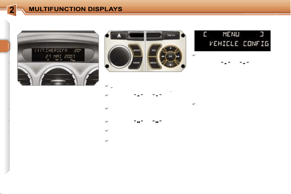
MONOCHROME SCREEN A
Controls
Displays on the screen
This displays the following information:
- the time,
- the date,
- the outside temperature* (this flashes
if there is a risk of ice),
- the status of the accesses (doors,
boot, ...),
- the audio sources (radio, CD, ...),
- the trip computer (refer to the end of
the section).
Warning messages (e.g.: "Emission
control system faulty") or information
messages (e.g.: "Boot open") may ap-
pear temporarily. These can be cleared
by pressing the
"ESC"
button.
General menu
Press the
"MENU"
button to gain
access to the
general menu
, then
press the
"
"
or
"
"
buttons to
scroll through the various menus:
- radio-CD,
- vehicle configuration,
- options,
- display settings,
- languages,
- units.
Press the
"OK"
button to select the
menu required.
From the RD4 audio equipment control
panel, you can:
press the
press the
"MENU"
button to gain
access to the
general menu
,
press the
"
"
or
"
"
buttons to
scroll through the items on the
screen,
press the
"MODE"
button to change
the permanent application (trip com-
puter, audio source, ...),
press the
"
"
or
"
"
buttons to
change a setting value,
press the
"OK"
button to confirm,
or
press the
"ESC"
button to abandon
the operation in progress.
Radio-CD
With the RD4 audio equipment switched
on, once the "Radio-CD" menu has been
selected you can activate or deactivate
the functions linked with use of the radio
(RDS, REG), the CD or the CD changer
(introscan, shuffle, CD repeat).
For further details concerning the
"Radio-CD" application, refer to the
RD4 part of the "Audio and Telematics"
section.
* With air conditioning only.
!
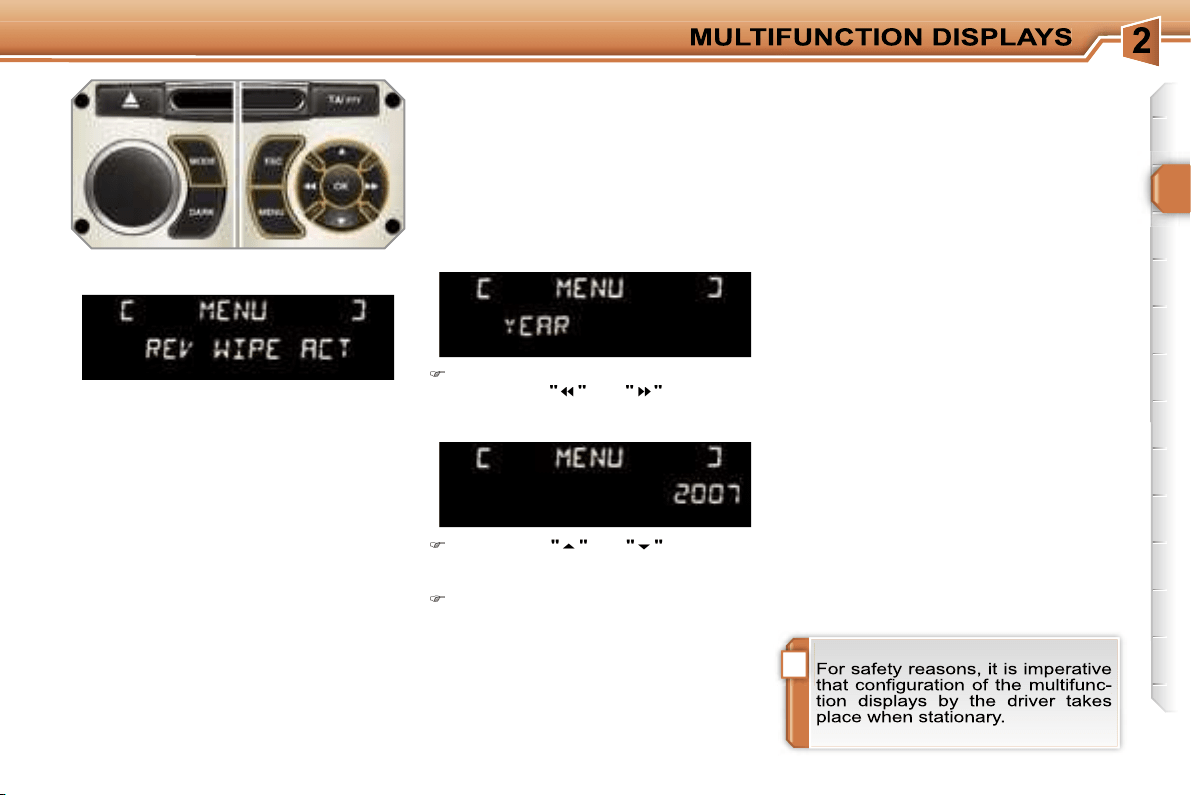
35
Display settings
Once the "Display settings" menu has
been selected, you can gain access to
the following settings:
- year,
- month,
- day,
- hour,
- minutes,
- 12 or 24 hour mode.
Languages
Once the "Languages" menu has been
selected, you can change the language
used by the display (Français, Italiano,
Nederlands, Portugues, Portugues-
Brasil, Deutsch, English, Espanol).
Units
Once the "Units" menu has been
selected, you can change the units of
the following parameters:
- temperature (°C or °F),
-
fuel consumption (l/100 km, mpg or km/l).
Once you have selected a setting,
press the
"
"
or
"
"
buttons to
change its value.
Press the
"
"
or
"
"
buttons to
switch respectively to the previous
or next setting.
Press the
"OK"
button to record the
change and return to the normal dis-
play or press the
"ESC"
button to
cancel.
Vehicle configuration
Options
Once the "Options" menu has been
selected, you can start diagnostics of
the status of the equipment (active, not
active, faulty).
Once the "Vehicle Configuration" menu
has been selected, you can activate or
deactivate the following equipment:
- selective unlocking (refer to the
"Access" section),
- wiper linked with reverse gear (refer to
the "Visibility" section),
- "follow-me-home" and welcome light-
ing (refer to the "Visibility" section),
- daytime lights (refer to the "Visibility"
section).
36
MONOCHROME SCREEN C AND
COLOUR SCREEN C
General menu
Displays on the screen
This displays the following information:
- the time,
- the date,
- the outside temperature* (this flashes
if there is a risk of ice),
- the status of the accesses (doors,
boot, ...),
- the audio sources (radio, CD, ...),
- the trip computer (refer to the end of
the section).
Warning messages (e.g.: "Emission
control system faulty") or information
messages (e.g.: "Automatic switching
on of the headlamps activated") may ap-
pear temporarily. These can be cleared
by pressing the
"ESC"
button.
"Audio functions" menu
Controls
From the RD4 audio equipment control
panel, you can:
press the
"MENU"
button to gain
access to the
access to the
general menu
,
press the
"
"
or
"
"
buttons to
scroll through the items on the
screen,
press the
"MODE"
button to change
the permanent application (trip com-
puter, audio source, ...),
press the
"
"
or
"
"
buttons to
change a setting value,
press the
"OK"
button to confirm,
or
press the
"ESC"
button to abandon
the operation in progress.
Press the
"MENU"
button to gain
access to the
general menu
:
- audio functions,
- vehicle diagnostics,
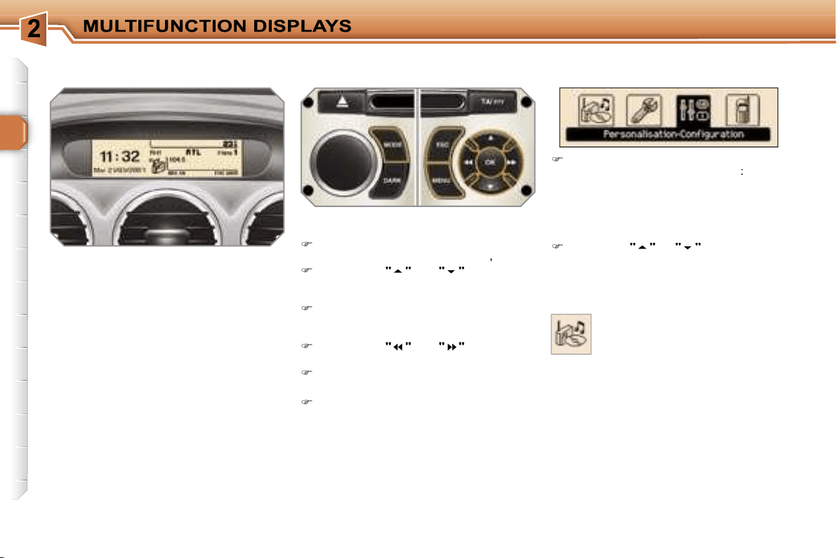
- personalisation-configuration,
- telephone (hands-free kit).
Press the
"
"
or
"
"
buttons to se-
lect the menu required, then confirm
by pressing the
"OK"
button.
* With air conditioning only.
With the RD4 audio equipment switched
on, once this menu has been selected
you can activate or deactivate the func-
tions linked with use of the radio (RDS,
REG, RadioText), the CD or the CD
changer (introscan, shuffle, CD repeat).
For further details concerning the "Au-
dio functions" application, refer to the
RD4 part of the "Audio and Telematics"
section.
37
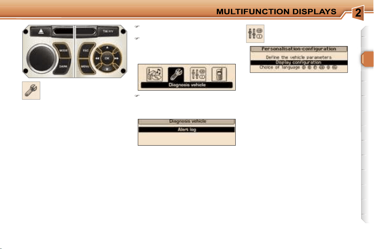
"Vehicle diagnostics"
menu
Press the
"MENU"
button to gain
access to the general menu.
Press the arrows, then the
"OK"
button to select the
"Vehicle diag-
nostics"
menu.
On the
"Vehicle diagnostics"
menu,
select the following application:
Warnings log
This summarises the active warning
messages, displaying them in succes-
sion on the multifunction display.
Once this menu has been selected, you
can consult information concerning the
status of the vehicle, such as the warn-
ings log.
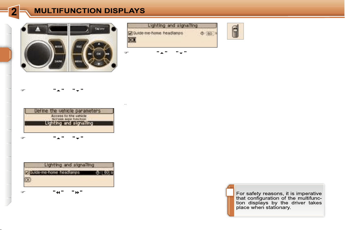
Define the vehicle parameters
Once this menu has been selected, you
can activate or deactivate the following
equipment:
- selective unlocking (refer to the
"Access" section),
- wiper linked with reverse gear (refer to
the "Visibility" section),
- "follow-me-home" and welcome lighting
(refer to the "Visibility" section),
- ambient lighting (refer to the "Visibility"
section),
- daytime lights (refer to the "Visibility"
section).
"Personalisation-
Configuration" menu
Once this menu has been selected, you
can gain access to the following func-
tions:
- define the vehicle parameters,
- display configuration,
- selection of the language.
!
38
"Telephone" menu
Display configuration
Once this menu has been selected, you
can gain access to the following set-
tings:
tings:
- brightness-video setting,
- date and time setting,
- selection of the units.
Selection of the language
Once this menu has been selected,
you can change the language used by
the display (Deutsch, English, Espanol,
Français, Italiano, Nederlands, Portu-
gues, Portugues-Brasil).
Example:
setting of the duration of the
"follow-me-home" lighting
Press the
"
"
or
"
"
buttons, then
the
"OK"
button to select the menu
required.
Press the
"
"
or
"
"
buttons, then
the
"OK"
button to select the "Fol-
low-me-home lighting" line.
Press the
"
"
or
"
"
buttons to set
the value required (15, 30 or 60 sec-
onds), then press the
"OK"
button to
confirm.
Press the
"
"
or
"
"
buttons, then
the
"OK"
button to select the
"OK"
box and confirm or press the
"ESC"
button to cancel.
With the RD4 audio equipment switched
on, once this menu has been select-
ed you can configure your Bluetooth
hands-free kit (matching), consult the
various telephone directories (calls log,
services, ...) and manage your commu-
nications (pick up, hang up, call waiting,
secret mode, ...).
For further details concerning the "Tele-
phone" application, refer to the RD4 part
of the "Audio and Telematics" section.
39
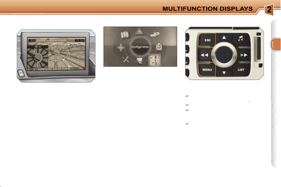
Displays on the screen
When the RT4 GPS audio/telephone is
switched on, select the menu which cor-
responds to the following applications:
- the satellite navigation system,
- the guidance on the map,
- the traffic information,
- the audio sources (radio, CD, ...),
- the telephone and the phonebooks,
- the configuration of the screen and
the setting of the vehicle equipment
parameters,
- the displaying of videos,
- the vehicle diagnostics.
Controls
When the screen is open, it displays the
following information automatically and
directly:
- the time,
- the date,
- the outside temperature (if there is
a risk of ice, you are warned by a
message).
Warning messages (e.g.: "Fuel level
low") and vehicle function status mes-
sages (e.g.: "Automatic lighting active")
may appear temporarily. These can be
cleared by pressing the
"ESC"
button.
From the RT4 GPS audio/telephone
control panel, to select one of the ap-
plications:
press the
"MENU"
button to gain
access to the
general menu
,
turn the navigator to move the selection,
press the navigator to confirm the
selection,
or
press the
"ESC"
button to abandon
the operation in progress and return
to the previous display.
For further details regarding these
applications, refer to the RT4 part of
the "Audio and Telematics" section.
RETRACTABLE 16/9 COLOUR
SCREEN
General menu
i
i
40
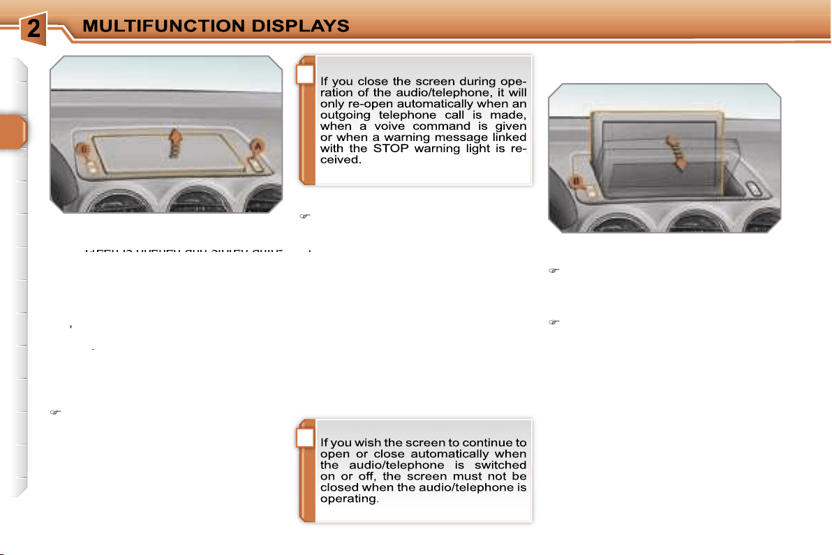
Access to the screen
Opening the screen
With the screen stored, press control
A
to open it.
The screen opens automatically when
the ignition is switched on, when the au-
dio/telephone is switched on, when an
outgoing telephone call is made, when
a voice command is given and when a
warning message linked with the STOP
warning light is received.
This screen is opened and stored auto-
This screen is opened and stored auto-
matically.
However, you can also open it, store it
and adjust it using the various manual
controls:
- opening or storing by means of control
A
,
- angle adjustments by means of con-
trol
B
.
It is also fitted with safety auto-reverse
protection.
Closing the screen
With the screen open, press control
A
to store it.
The screen is stored automatically
when the ignition is switched off, after
when the ignition is switched off, after
approximately three seconds, if the au-
dio/telephone is off.
When the screen is open, you can
adjust it precisely in different ways:
press the corresponding part of con-
trol
B
to move the screen towards
you or towards the windscreen,
or
push or pull the screen gently by
hand.
Adjusting the position of the screen
Safety auto-reverse
If the screen meets an obstacle as it
opens or closes, the movement stops
immediately and is reversed by a few
millimetres.
After clearing the obstacle, issue the
command required again.
Storing the position of
the screen
The system has four pre-set positions
in its memory.
Each time the screen is closed, the
system stores the last position of the
screen.
Each time the screen is re-opened, the
system returns the screen to the pre-set
position closest to that stored.
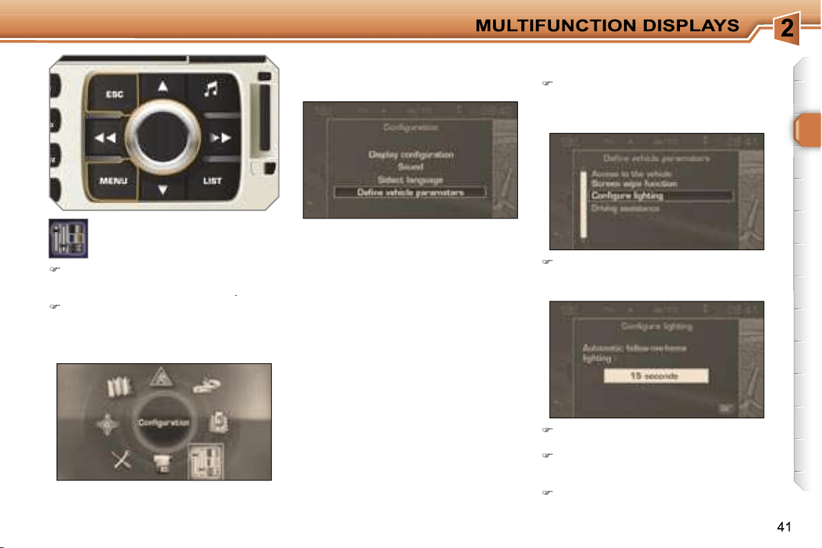
Define the vehicle parameters
Once the "Define the vehicle parameters"
menu has been selected, you can activate
or deactivate certain driving and comfort
equipment:
- selective unlocking (refer to the
"Access" section),
- wiper linked with reverse gear (refer to
the "Visibility" section),
- follow-me-home and welcome lighting
(refer to the "Visibility" section),
- ambient lighting (refer to the "Visibil-
ity" section),
- daytime lights (refer to the "Visibility"
section),
- directional headlamps (refer to the
"Visibility" section).
Example:
setting the duration of the
follow-me-home lighting
Turn the navigator to select the
"Lighting configuration"
menu,
then press the navigator to confirm.
Select the line "Duration of follow-
me-home lighting" then confirm.
"Configuration" menu
Once this menu has been selected, you
can gain access to the following func-
tions:
Select the duration then press the
navigator.
Turn the navigator to set the value
required (15, 30 or 60 seconds), then
press the navigator.
Select the
"OK"
box, then confirm.
Press the
"MENU"
button on the
RT4 GPS audio/telephone to gain
access to the
general menu
.
Turn the navigator to select the
"Configuration"
menu, then press
the navigator to confirm.
!
42
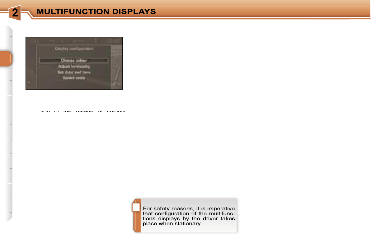
Once the "Display configuration" menu
has been selected, you gain access to
the following parameters:
- selection of the palette of colours
- selection of the palette of colours
available for the display,
- setting of the brightness and brilliance
of the display,
- setting of the date and time (12 or
24 hour mode, adjustment of the min-
utes on GPS),
- selection of the units (temperature in
°Celsius or °Fahrenheit; consumption
in l/100 km or mpg or km/l).
Display configuration
Once the "Sounds" menu has been se-
lected, you gain access to the following
parameters:
- setting of the voice commands,
- setting of the voice synthesiser (volume,
male or female),
- activation of the auxiliary input AUX.
Selecting the the language
Sounds
Once the "Language selection" menu
has been selected, you gain access to
the following parameters:
- selection of the display language
(Français, English, Italiano, Portugues,
Espanol, Deutsch, Nederlands),
- selection of the language used for
the information and voice commands
(Français, English, Italiano, Portugues,
Espanol, Deutsch, Nederlands).
43
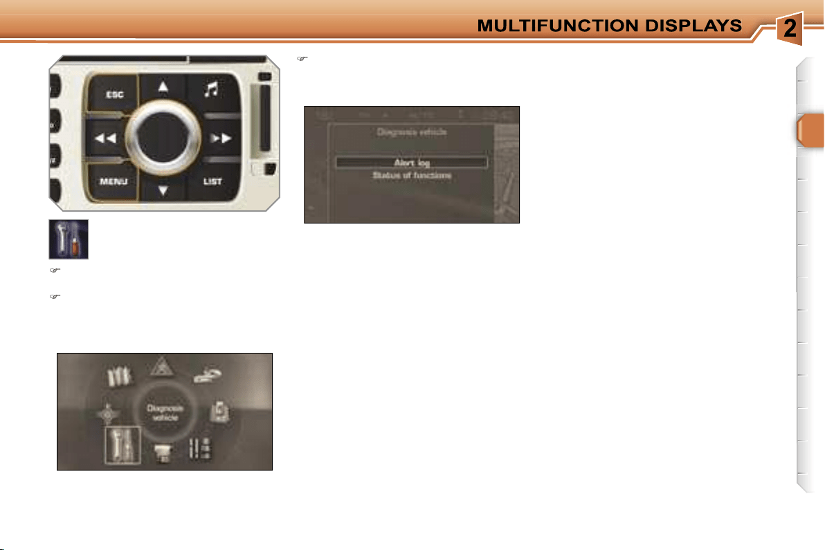
Warnings log
This summarises the active warning
messages, displaying them in succes-
sion on the multifunction display.
"Vehicle diagnostics"
menu
Press the
"MENU"
button to gain
access to the general menu.
Turn the navigator and press it to
select the
"Vehicle diagnostics"
menu.
On the
"Vehicle diagnostics"
menu, select one of the following
applications:
Status of the functions
This summarises the active or inactive
status of the functions present on the
vehicle.
44
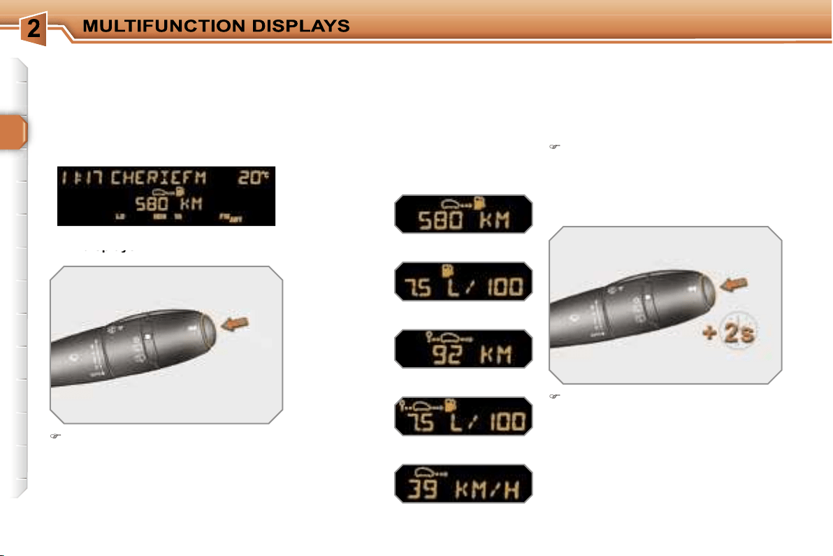
TRIP COMPUTER
Press the button, located at the end
of the
wipers stalk
, to display the
various items of trip computer data
in succession.
The trip computer data is the following:
System which provides current infor-
mation concerning the route travelled
(range, consumption, ...).
Press the control for more than
two seconds to reset the distance
travelled, the average consumption
and the average speed to zero.
Monochrome screen A
Zero reset
Data displays
Data displays
- the range,
- the current consumption,
- the current consumption,
- the distance travelled,
- the average consumption,
- the average speed.
The next press then returns you to
the normal display.
!
i
i
46
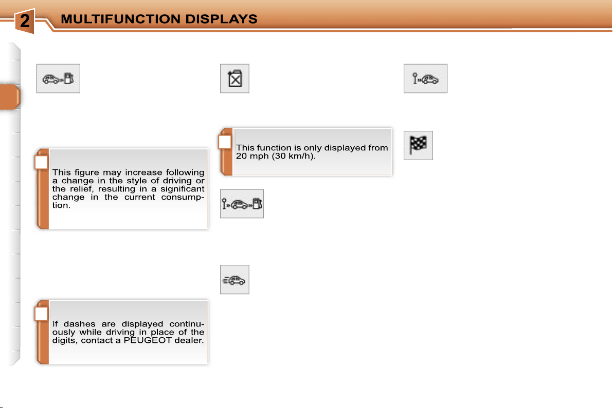
A few definitions…
When the range falls below 20 miles
(30 km), dashes are displayed. After fill-
ing with at least 5 litres of fuel, the range
is recalculated and is displayed when it
exceeds 60 miles (100 km).
Range
(km or miles)
This indicates the distance
which can still be travelled
with the fuel remaining in the tank in
relation to the average consumption
over the last few miles (kilometres) tra-
velled.
Current consumption
(l/100 km or km/l or mpg)
This is the average quantity of
fuel consumed during the last
few seconds.
Average consumption
(l/100 km or km/l or mpg)
This is the average quantity
of fuel consumed since the
last trip computer zero re-
set.
Distance travelled
(km or miles)
This indicates the distance
travelled since the last trip
computer zero reset.
Average speed
(km/h or mph)
This is the average speed cal-
culated since the last trip com-
puter zero reset (ignition on).
Distance remaining to
destination
(km or miles)
This is the distance remaining
to be travelled to the final destination. It
is either calculated instantly by the navi-
gation system, if guidance is activated,
or entered by the user.
If the distance is not entered, dashes
are displayed in place of the digits.
i
45
- the current information tab
with:
• the range,
• the current
consumption,
• the distance remaining
to be travelled,
Route zero reset
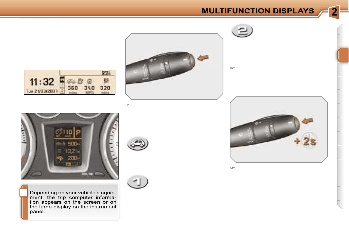
Monochrome screen C and
colour screen C
Press the button, located at the end of
the
wipers stalk
, to display the vari-
ous trip computer tabs in succession:
Data displays
When the route required is displayed,
press the control for more than two
seconds.
- the route
"1"
tab with:
• the distance travelled,
• the average
consumption,
• the average speed,
for the first route.
- the route
"2"
tab with:
• the distance travelled,
• the average
consumption,
• the average speed,
for the second route.
Routes
"1"
and
"2"
are independent
but their use is identical.
Route
"1"
permits, for example, daily
calculations, and route
"2"
monthly cal-
culations.
TRIP COMPUTER
System which provides current infor-
mation concerning the route travelled
(range, consumption, …).
Instrument panel large display
Pressing the button again returns
you to the normal display.

!
i
i
46
A few definitions…
When the range falls below 20 miles
(30 km), dashes are displayed. After fill-
ing with at least 5 litres of fuel, the range
is recalculated and is displayed when it
exceeds 60 miles (100 km).
Range
(km or miles)
This indicates the distance
which can still be travelled
with the fuel remaining in the tank in
relation to the average consumption
over the last few miles (kilometres) tra-
velled.
Current consumption
(l/100 km or km/l or mpg)
This is the average quantity of
fuel consumed during the last
few seconds.
Average consumption
(l/100 km or km/l or mpg)
This is the average quantity
of fuel consumed since the
last trip computer zero re-
set.
Distance travelled
(km or miles)
This indicates the distance
travelled since the last trip
computer zero reset.
Average speed
(km/h or mph)
This is the average speed cal-
culated since the last trip com-
puter zero reset (ignition on).
Distance remaining to
destination
(km or miles)
This is the distance remaining
to be travelled to the final destination. It
is either calculated instantly by the navi-
gation system, if guidance is activated,
or entered by the user.
If the distance is not entered, dashes
are displayed in place of the digits.
47
VENTILATION
System which creates and maintains
comfortable conditions in the vehicle’s
passenger compartment.
Air treatment
The incoming air follows various routes
depending on the controls selected by
the driver:
- direct arrival in the passenger com-
partment (air intake),
- passage through a heating circuit
(heating),
- passage through a cooling circuit (air
conditioning).
The temperature control enables you to
obtain the level of comfort required by
mixing the air of the various circuits.
The air distribution control enables you
to diffuse the air in the passenger com-
partment combining several air vents.
The air flow control enables you to
increase or reduce the speed of the
ventilation blower.
Air intake
The air circulating in the passenger com-
partment is filtered and originates either
from the outside via the grille located at
the base of the windscreen or from the
inside in air recirculation mode.
Control panel
The controls of this system are grouped
together on control panel
A
on the cen-
tre console. Depending on the model,
the functions offered are:
- the level of comfort required,
- the air flow,
- the air distribution,
- the de-icing and demisting,
- the manual or automatic air conditioning
controls.
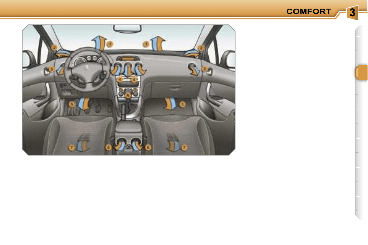
Air diffusion
1.
Windscreen de-icing or demisting
vents.
2.
Front side window de-icing or
demisting vents.
3.
Side adjustable and closing vents.
4.
Central adjustable and closing
vents.
5.
Air outlets to the front footwells.
6.
Adjustable and closing vents for
the rear passengers.
7.
Air outlets to the rear footwells.
i
48
RECOMMENDATIONS FOR VENTILATION AND AIR
CONDITIONING
i
49
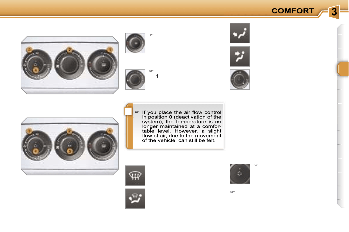
2. Air flow adjustment
Turn the dial from position
1
to position
5
to obtain a
comfortable air flow.
Windscreen, side windows and
footwells.
Footwells.
(vents closed)
Central and side vents.
Turn the dial from blue
(cold) to red (hot) to adjust
the temperature to your re-
quirements.
Windscreen and side windows.
1. Temperature adjustment
The air distribution can be
adapted by placing the dial in
an intermediate position.
The heating/ventilation or air conditio-
ning systems can only operate with the
engine running.
4. Air intake/Air recirculation
The intake of exterior air prevents misting
of the windscreen and side windows.
The recirculation of interior air insulates
the passenger compartment from exte-
rior odours and smoke.
Return to exterior air intake as soon as
possible to prevent deterioration of the
the air quality and avoid misting.
3. Air distribution adjustment
Press the button to recir-
culate the interior air. The
indicator light comes on to
confirm this.
Press the button again to permit
the intake of exterior air. The indica-
tor light switches off to confirm this.
HEATING/VENTILATION
MANUAL AIR CONDITIONING

i
50
De-icing - Demisting
To quickly de-ice or demist the winds-
creen and side windows:
place the air intake control
4
in the
"Exterior air intake" position,
place the air distribution dial
3
in the
"Windscreen position",
place the temperature
1
and air flow
2
dials at maximum,
close the central vents,
The control button is located on
the heating or air conditioning
system control panel.
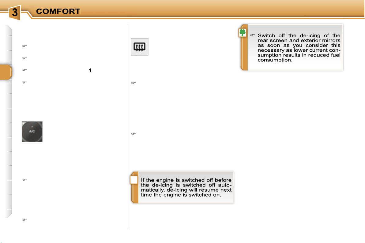
REAR SCREEN DE-ICING
Switching on
The rear screen de-icing can only
operate when the engine is running.
Press this button to de-ice the rear
screen and the exterior mirrors. The
indicator light associated with the
button comes on.
Switching off
The de-icing switches off automatically
to prevent an excessive consumption of
current.
It is possible to stop the de-icing op-
eration before it is switched off au-
tomatically by pressing the button
again. The indicator light associated
with the button switches off.
5. Air conditioning On/Off
The air conditioning is desi-
gned to operate effectively in
all seasons, with the windows
closed.
It enables you to:
- lower the temperature, in summer,
- increase the effectiveness of the
demisting in winter, above 0 °C.
Switching on
Press the
"A/C"
button, the associ-
ated indicator light comes on.
The air conditioning does not op-
erate when the air flow adjustment
control 2 is in position "0".
Switching off
Press the
"A/C"
button again, the
associated indicator light switches off.
above 0 °C, switch on the air condi-
tioning by pressing the
"A/C"
button.
i
50
De-icing - Demisting
To quickly de-ice or demist the winds-
creen and side windows:
place the air intake control
4
in the
"Exterior air intake" position,
place the air distribution dial
3
in the
"Windscreen position",
place the temperature
1
and air flow
2
dials at maximum,
close the central vents,
The control button is located on
the heating or air conditioning
system control panel.
REAR SCREEN DE-ICING
Switching on
The rear screen de-icing can only
operate when the engine is running.
Press this button to de-ice the rear
screen and the exterior mirrors. The
indicator light associated with the
button comes on.
Switching off
The de-icing switches off automatically
to prevent an excessive consumption of
current.
It is possible to stop the de-icing op-
eration before it is switched off au-
tomatically by pressing the button
again. The indicator light associated
with the button switches off.
5. Air conditioning On/Off
The air conditioning is desi-
gned to operate effectively in
all seasons, with the windows
closed.
It enables you to:
- lower the temperature, in summer,
- increase the effectiveness of the
demisting in winter, above 0 °C.
Switching on
Press the
"A/C"
button, the associ-
ated indicator light comes on.
The air conditioning does not op-
erate when the air flow adjustment
control 2 is in position "0".
Switching off
Press the
"A/C"
button again, the
associated indicator light switches off.
above 0 °C, switch on the air condi-
tioning by pressing the
"A/C"
button.
i i
51
The air conditioning only operates when
the engine is running.
The driver and his front pas-
senger can each adjust the
temperature to their require-
ments.
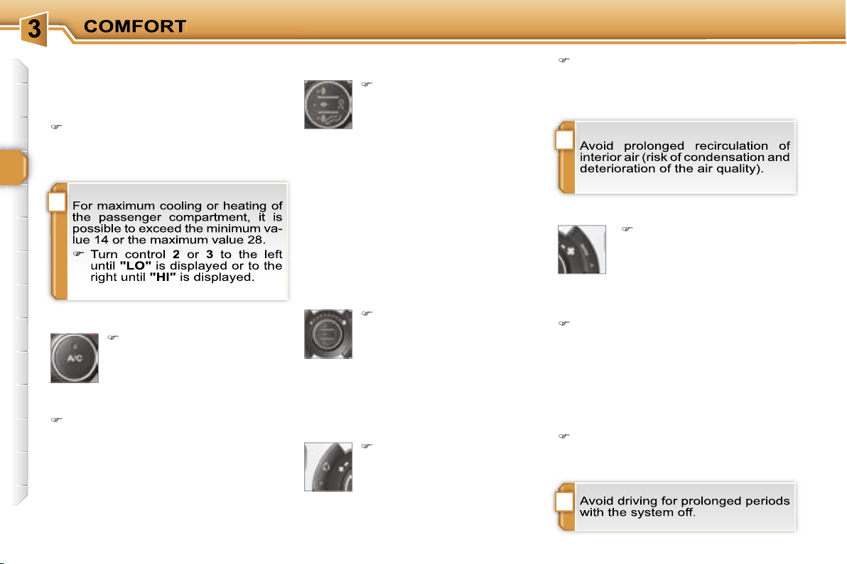
Turn control
2
or
3
to the left or to
the right respectively to decrease or
increase this value.
A setting around the value 21
provides
optimum comfort. However, depending
on your requirements, a setting between
18 and 24 is normal.
You are advised to avoid a left/right
setting difference of more than 3.
4. Automatic visibility programme
The automatic comfort pro-
gramme may not be sufficient
to quickly demist or de-ice the
windscreen and side windows
(humidity, several passen-
gers, ice, etc.).
In this case, select the automatic
visibility programme.
The system automatically controls the
air conditioning, the air flow and the air
intake and provides optimum distribu-
tion of the ventilation to the windscreen
and side windows.
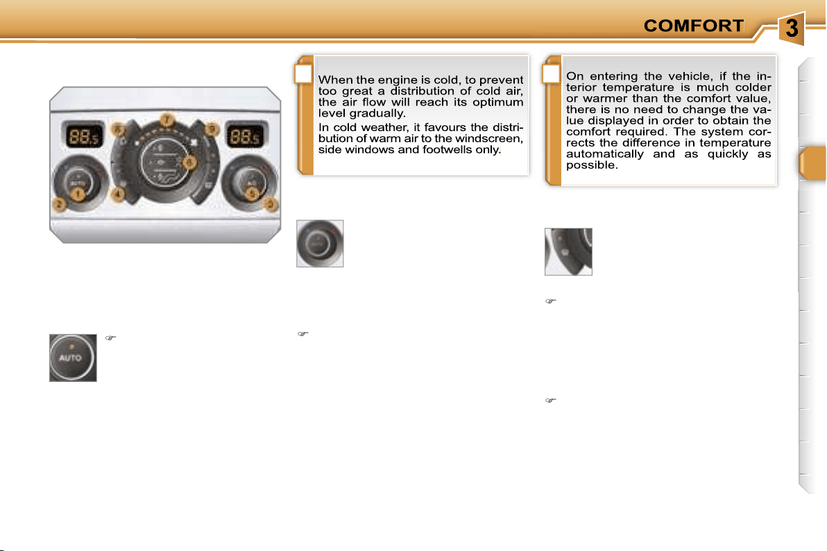
Automatic operation
1. Automatic comfort programme
Press the
"AUTO"
button.
The indicator light on the
button comes on.
2. Driver’s side adjustment
3. Passenger side adjustment
DUAL ZONE AUTOMATIC AIR
CONDITIONING
We recommend the use of this mode:
it permits automatic and optimised ad-
justment of all of the functions, passen-
ger compartment temperature, air flow,
air distribution and air recirculation, in
accordance with the comfort value that
you have chosen.
This system is designed to operate
effectively in all seasons, with the
windows closed.
The value indicated on the display cor-
responds to a level of comfort and not
to a temperature in degrees Celsius or
Fahrenheit.
To switch it off, press the
"visibility"
button again or press the
"AUTO"
button, the indicator light on the but-
ton switches off and the indicator light
on the
"AUTO"
button comes on.
!
!
i
52
Manual operation
If you wish, you can make a different
choice from that offered by the system
by changing a setting. The other func-
tions will still be controlled automatically.
Pressing the
"AUTO"
button returns
the system to completely automatic
operation.
Press this button to switch
off the air conditioning.
6. Air distribution adjustment
Press one or more but-
tons to direct the air flow
towards:
7. Air flow adjustment
Turn this control to the left
to decrease the air flow or
to the right to increase the
air flow.
8. Air intake/Air recirculation
Switching the system off
Turn the air flow control to the left
until all of the indicator lights switch
off.
This action switches off all of the func-
tions of the system.
Temperature related comfort is no long-
er guaranteed but a slight flow of air,
due to the movement of the vehicle, can
still be felt.
Turn the air flow dial to the right or
press the
"AUTO"
button to reacti-
vate the system with the values set
before it was switched off.
Press this button for recir-
culation of the interior air.
The indicator light on the
button comes on.
5. Air conditioning On/Off
- the windscreen and side windows
(de-icing or demisting),
- the windscreen, the side windows and
the vents,
- the windscreen, the side windows, the
vents and the footwells,
- the vents and the footwells,
- the vents,
- the footwells,
- the windscreen, the side windows and
the footwells.
The air flow indicator lights, between
the two fans, come on progressively in
relation to the value requested.
As soon as possible, press this but-
ton again to permit the intake of out-
side air and prevent condensation.
The indicator light on the button swit-
ches off.
9. Mono zone/Dual zone
Press this button to equali-
se the comfort value on the
passenger side with that
on the driver's side (mono
zone). The indicator light
on the button comes on.
Air recirculation enables the passenger
compartment to be isolated from exte-
rior odours and smoke.
Switching the system off could result in
discomfort (humidity, condensation).
Press this button again to return to
automatic operation of the air con-
ditioning. The indicator light on the
"A/C"
button comes on.
!
i
i
53
FRAGRANCE DIFFUSER
System permitting the diffusion of a fra-
grance in the passenger compartment
in accordance with your requirements,
by means of the adjustment dial and the
various fragrance cartridges available.
Fitting the cartridge
Remove the cartridge from the sealing
case.
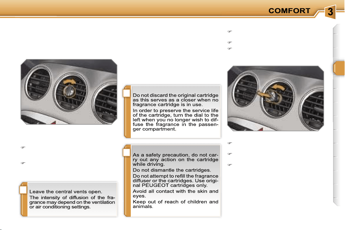
Install the cartridge in the fascia
(flower at top right).
Press the dial and turn it a quarter of
a turn to the right.
Adjustment dial
This dial permits adjustment of the
intensity of diffusion of the fragrance.
Turn the dial to the right to permit
diffusion of the fragrance (horizontal
position).
Turn the dial to the left to stop diffusion
of the fragrance (vertical position).
Fragrance cartridge
This cartridge can be removed easily.
You can change it at any time and store
it in the sealed case which keeps it
closed once it has been opened.
You can obtain different fragrance
cartridges from PEUGEOT dealers.
Removing the cartridge
Turn the dial a quarter of a turn fully
to the left.
Remove the cartridge from the fascia.
Refit its sealing case.
54
FRONT SEATS
Seat consisting of a seat cushion, a seat
back and a head restraint which can all
be adjusted to adapt your position for
ease of driving and comfort.
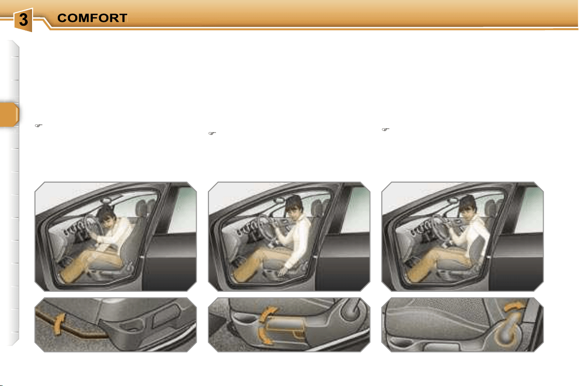
Forwards-backwards adjustment
Raise the control and slide the seat
forwards or backwards.
Driver’s or passenger’s seat height
adjustment
Pull the control upwards to raise or
push it downwards to lower, as many
times as necessary, to obtain the po-
sition required.
Seat back angle adjustment
Push the control rearwards.
Manual adjustments
i
55
FRONT SEATS
Seat consisting of a seat cushion, a seat
back and a head restraint which can all
be adjusted to adapt your position for
ease of driving and comfort.
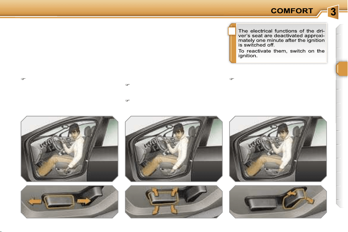
Forwards-backwards adjustment
Push the control forwards or rear-
wards to slide the seat.
Seat cushion height and angle
adjustment
Tilt the rear part of the control
upwards or downwards to obtain
the required height.
Tilt the front part of the control
upwards or downwards to obtain
the required angle.
Seat back angle adjustment
Tilt the control forwards or rearwards
to adjust the angle of the seat back.
Driver’s seat electric
adjustments
!
!
56
Access to the rear seats (3-door)
Pull the control upwards to fold the
seat back and move the seat forward.
When put back in place, the seat
returns to its initial position.
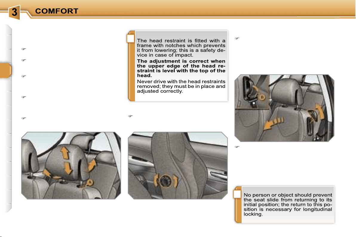
Head restraint height and angle
adjustment
To raise the head restraint, pull it for-
wards and upwards at the same time.
To remove the head restraint, press
the lug
A
and pull the head restraint
upwards.
To put the head restraint back in
place, engage the head restraint
stems in the openings keeping them
in line with the seat back.
To lower the head restraint, press
the lug
A
and the head restraint at
the same time.
To adjust the angle of the head
restraint, tilt its lower part forwards
or rearwards.
Lumbar adjustment
Turn the dial to obtain the correct
lumbar position.
Additional adjustments
Lower the support
B
incorporated in
the control to rest the seat belt on it.
It enables you to retrieve the seat
belt more easily when you need to
put it back on.
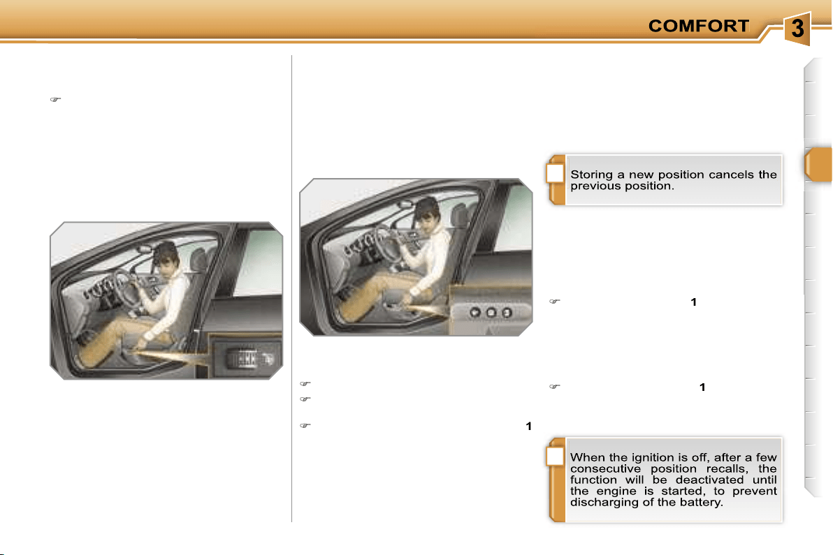
i
!
57
Heated seats control
With the engine running, the front seats
can be heated separately.
Use the adjustment dial, placed on
the side of each front seat, to switch
on and select the level of heating re-
quired:
0:
Off.
1:
Low.
2:
Medium.
3:
High.
Storing driving positions
System which takes into account the
electrical settings of the driver’s seat
and exterior mirrors. It enables you to
store up to two positions using the but-
tons on the side of the driver’s seat and
two further driving positions using the
two remote control keys.
Recalling a stored position
When the vehicle is unlocked, the dri-
ver’s seat and the exterior mirrors re-
turn to the position stored by the remote
control key.
Storing a position
Using buttons M/1/2
Switch on the ignition.
Adjust your seat and your exterior
mirrors.
Press button
M
, then press button
1
or
2
within four seconds.
An audible signal is heard indicating
that the storing has been taken into
account.
Using the remote control keys
When the vehicle is locked, the remote
control key stores the position of the dri-
ver’s seat and exterior mirrors.
Each remote control key can store one
specific setting.
Ignition on
Briefly press button
1
or
2
to recall
the corresponding position.
An audible signal is heard indicating
the end of the adjustment.
Vehicle moving
Press and hold button
1
or
2
until the
audible signal is heard indicating the
end of the adjustment.
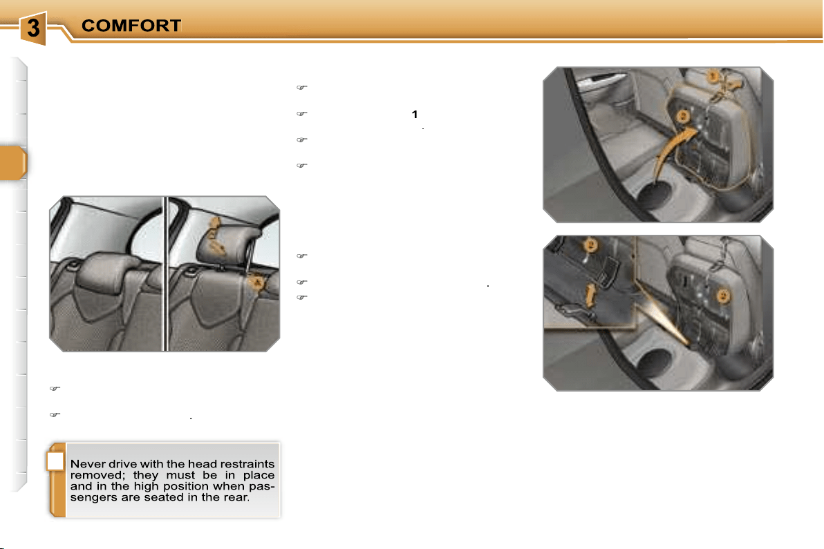
!
58
REAR SEATS
Bench seat the left-hand (2/3) or
right-hand (1/3) section of which can be
folded to adapt the boot load space.
Rear head restraints
These have a high position (comfort
and safety) and a low position (rear vis-
ibility).
They can also be removed; to remove
them:
pull the head restraint fully forwards
and upwards at the same time,
then, press the lug
A
.
Removing the seat cushion
Move the corresponding front seat
forwards.
Pull the handle
1
forwards to raise
the seat cushion
2
.
Tilt the seat cushion
2
fully against
the front seat.
Remove the seat cushion
2
from its
fixings by pulling upwards.
Refitting the seat cushion
Position the seat cushion
2
vertically
in its fixings.
Fold down the seat cushion
2
.
Press on the seat cushion to secure it.
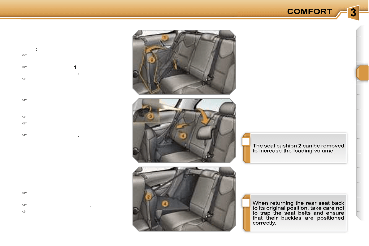
!
i
59
Folding the seat
In order to fold a rear seat without any
risk of damage,
always start with the
seat cushion, never with the seat
back
:
move the corresponding front seat
forwards if necessary,
pull the handle
1
forwards to raise
the seat cushion
2
,
tilt the seat cushion
2
fully against
the front seat,
Returning the seat back to its
original position
When returning the rear seat back to its
original position:
put the seat back
4
in the upright
position and secure it,
fold the seat cushion
2
,
put the head restraints back in place.
check that the seat belt is positioned
correctly on the side of the seat
back,
remove the head restraints,
pull the control
3
forwards to release
the seat back
4
,
tilt the seat back
4
.
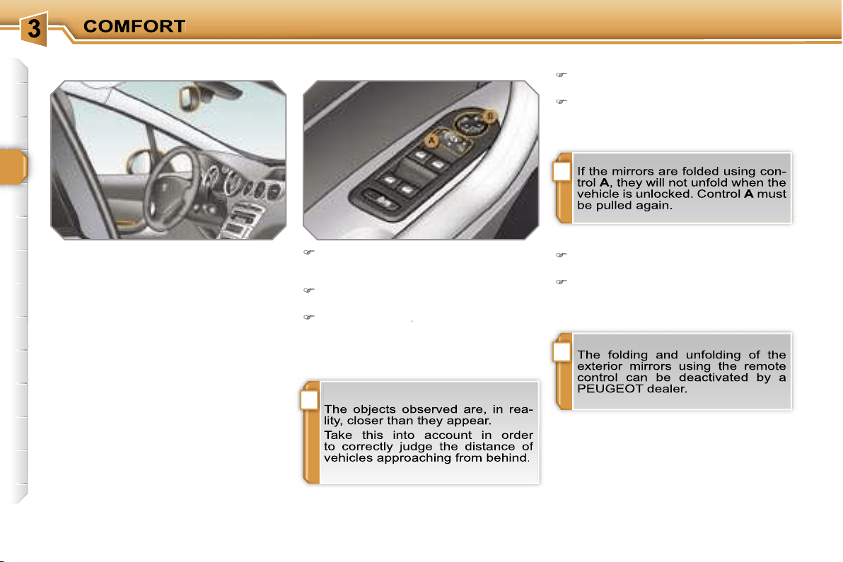
!
i
i
60
MIRRORS
Exterior mirrors
Each fitted with an adjustable mirror
permitting the lateral rearward vision
necessary for overtaking or parking.
They can also be folded for parking in
confined spaces.
Folding
from outside; lock the vehicle using
the remote control or the key.
from inside; with the ignition on, pull
control
A
rearwards.
Adjustment
Unfolding
from outside; unlock the vehicle
using the remote control or the key.
from inside; with the ignition on, pull
control
A
rearwards.
Move control
A
to the right or to the
left to select the corresponding mir-
ror.
Move control
B
in all four directions
to adjust.
Return control
A
to the central position.
A
A

!
61
Adjustment
Adjust the mirror so that the glass is di-
rected correctly in the "day" position.
Manual model
The mirror is fitted with a night-time
anti-dazzle device.
Day/night position
Pull the lever to change to the "night"
anti-dazzle position.
Push the lever to change to the normal
"day" position.
Automatic tilting in reverse gear
System which provides a view of the
ground during parking manoeuvres in
reverse gear.
Switching on
With the engine running, engage re-
verse gear.
Move control
A
to the right or to the
left to select the corresponding mir-
ror.
The glass of the mirror selected tilts
downwards, in accordance with its pro-
gramming.
Programming
With the engine running, engage
reverse gear.
Select and adjust the left-hand and
right-hand mirrors in succession.
The adjustment is stored immediately.
Switching off
Exit reverse gear and wait twenty
seconds.
or
Return control
A
to the central posi-
tion.
The mirror glass returns to its initial po-
sition.
The mirror glass also returns to its initial
position:
- if the speed exceeds 6 mph (10 km/h),
- if the engine is switched off.
Interior mirror
Adjustable mirror providing a central
rearward view.
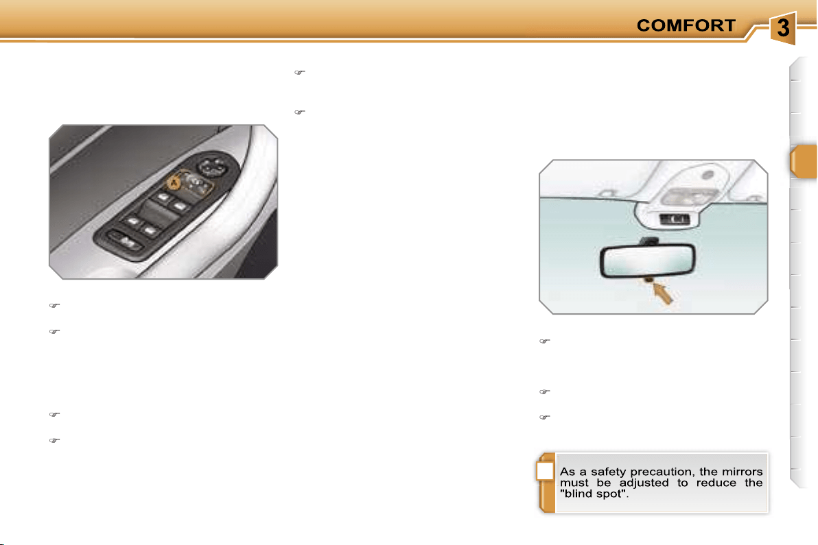

!
i
62
STEERING WHEEL ADJUSTMENT
The height and depth of the steering
wheel can be adjusted to adapt the dri-
ving position to the size of the driver.
Adjustment
When stationary,
pull the control to
unlock the steering wheel.
Adjust the height and depth.
Push the control to lock the steering
wheel.
Automatic day/night model
System which automatically and pro-
gressively changes between the day
and night uses.
In order to prevent dazzle, the interior
mirror glass darkens automatically in
relation to the intensity of the light from
the rear.
It lightens when the light (light beam of
following vehicles, sun...) decreases, so
guaranteeing optimum visibility.
Switching on
Switch on the ignition and press
switch
1
.
The indicator light
2
comes on and the
mirror operates automatically.
Switching off
Press switch
1
.
The indicator light
2
switches off and
the mirror remains in its lightest state.
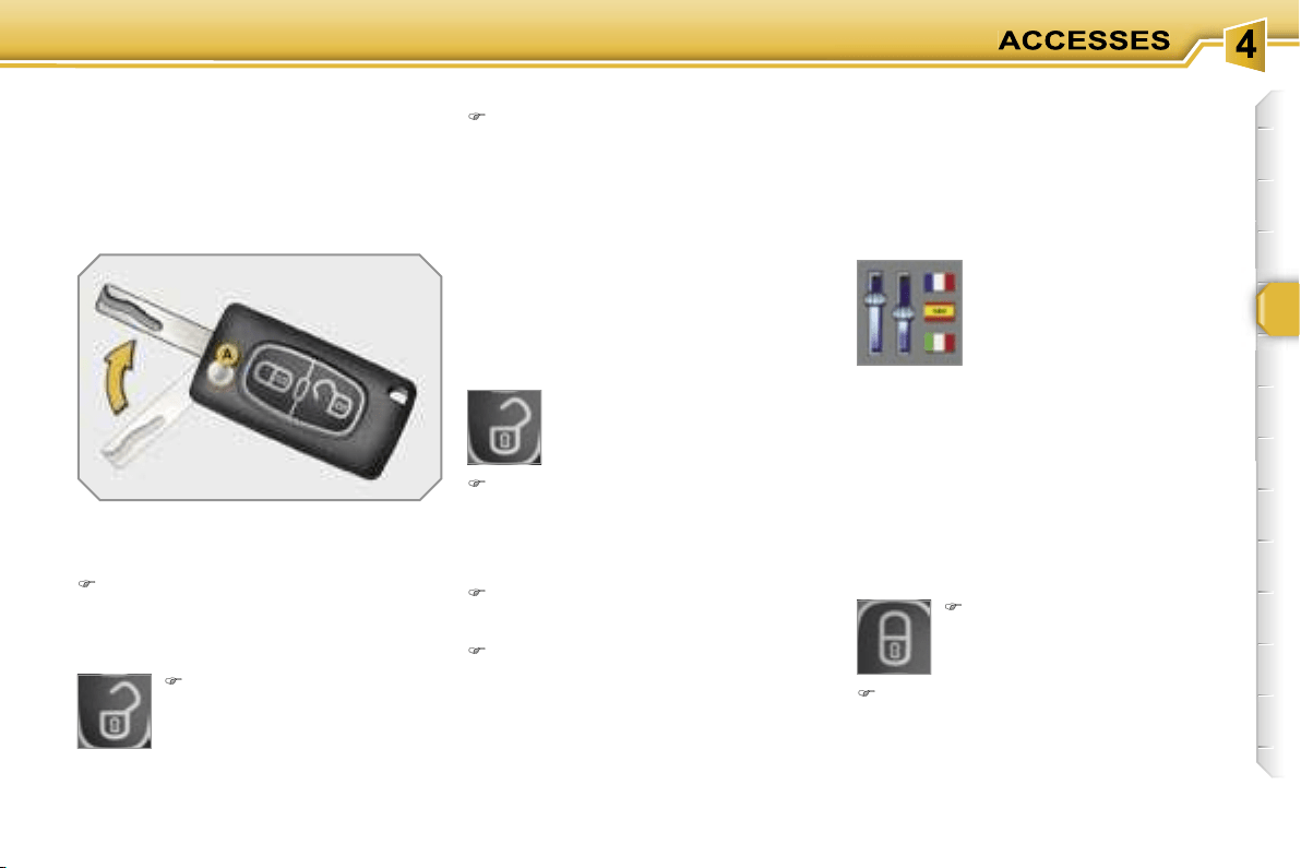
63
Locking the vehicle
Normal locking using the remote
control
Press the closed padlock
to lock the vehicle comple-
tely.
Press the open padlock
once to unlock the driver's
door only.
Press the open padlock again to un-
lock the other doors and the boot.
Selective unlocking using the
remote control
Each unlocking is confirmed by rapid
flashing of the direction indicators for
approximately two seconds.
According to version, the exterior mir-
rors unfold at the same time as the first
unlocking action.
Selective unlocking using the key
Turn the key to the left in the driver's
door lock once to unlock the driver's
door only.
Turn the key to the left in the driver's
door lock again to unlock the other
doors and the boot.
The complete or selective
unlocking parameter is set
via the multifunction dis-
play configuration menu.
Complete unlocking is activated by
default.
Press the closed padlock for more
than two seconds to close the win-
dows automatically in addition to
locking.
REMOTE CONTROL KEY
System which permits central unlock-
ing or locking of the vehicle using the
lock or from a distance. It is also used to
locate and start the vehicle, as well as
providing protection against theft.
Unfolding the key
First press button
A
to unfold the
key.
Unlocking the vehicle
Unlocking is confirmed by rapid flashing
of the direction indicators for approxi-
mately two seconds.
According to version, the exterior mir-
rors unfold at the same time.
Press the open padlock to
unlock the vehicle.
Complete unlocking using the key
Turn the key to the left in the driver's
door lock to unlock the vehicle.
Complete unlocking using the
remote control
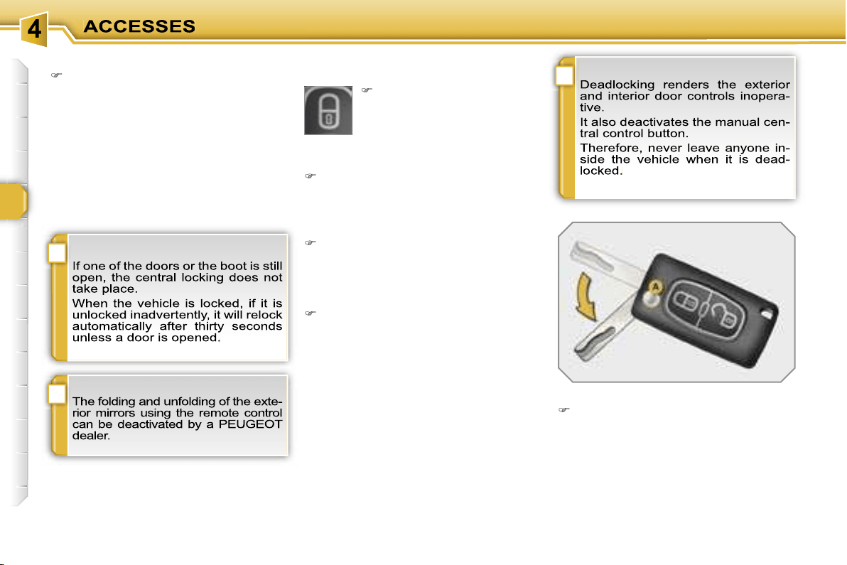
!
i
i
64
Deadlocking using the remote control
Normal locking using the key
Turn the key to the right in the dri-
ver's door lock to lock the vehicle
completely.
Locking is confirmed by fixed lighting of
the direction indicators for approximately
two seconds.
According to version, the exterior mir-
rors fold at the same time.
Deadlocking using the key
Turn the key to the right in the dri-
ver's door lock to lock the vehicle
completely and hold it in this position
for more than two seconds to cose
the windows automatically in addi-
tion to locking.
Turn the key to the right again within
five seconds to deadlock the vehicle.
Deadlocking is confirmed by fixed light-
ing of the direction indicators for ap-
proximately two seconds.
According to version, the exterior mir-
rors fold at the same time.
Folding the key
First press button
A
to fold the key.
Press the closed padlock to
lock the vehicle completely
or press the closed padlock
for more than two seconds
to close the windows auto-
matically in addition to loc-
king.
Press the closed padlock again
within five seconds to deadlock the
vehicle.
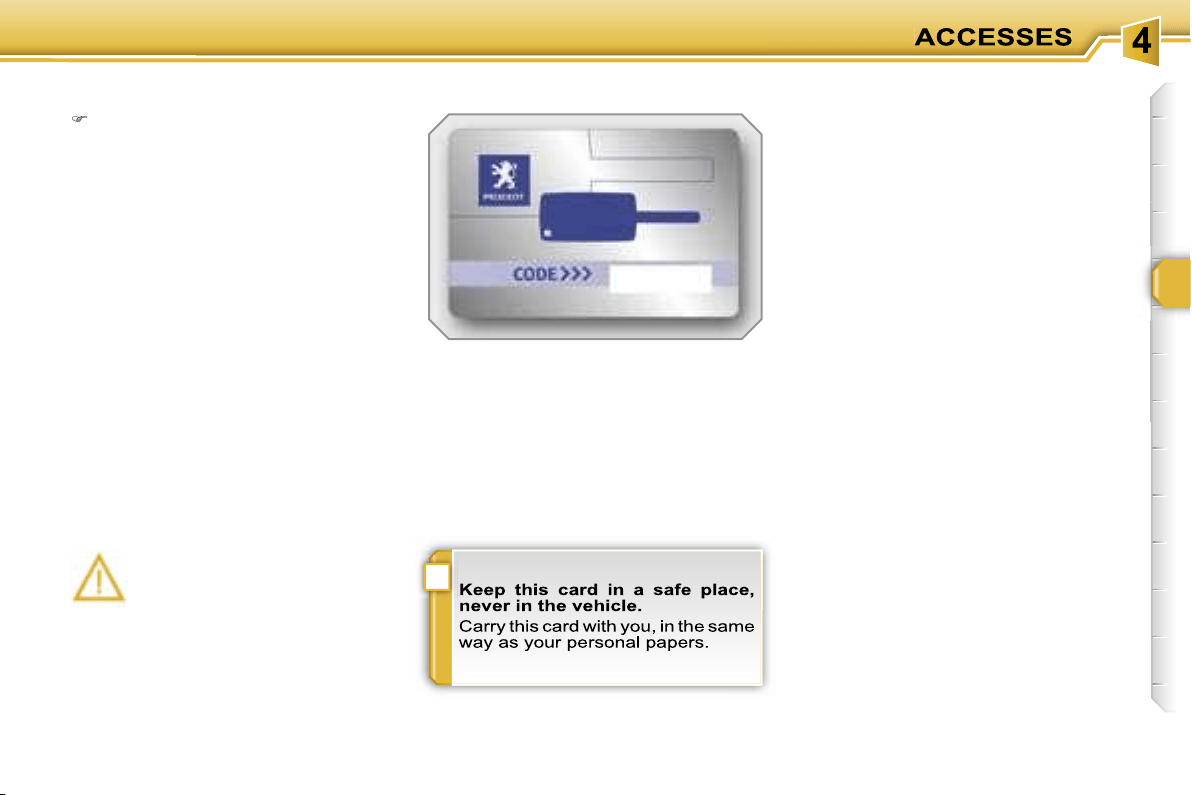
!
65
Locating your vehicle
Confidential card
Press the closed padlock to locate
your locked vehicle in a car park.
This is indicated by lighting of the cour-
tesy lights and dipped headlamps and
flashing of the direction indicators for a
few seconds.
Electronic engine immobiliser
The key contains an electronic chip
which has a special code. When the
ignition is switched on, this code must
be recognised in order for starting to be
possible.
This electronic engine immobiliser locks
the engine management system a few
minutes after the ignition is switched off
and prevents starting of the engine by
anyone who does not have the key.
Anti-theft protection
This is given to you with the duplicate
keys on delivery of your vehicle.
It bears the identification code necessary
for any work on the electronic engine im-
mobiliser by a PEUGEOT dealer.
This code is hidden by a film which
should not be removed until necessary.
In the event of a malfunction,
you are informed by lighting of
this warning light, an audible
signal and a message on the
multifunction display.
In this case, your vehicle does not start;
contact a PEUGEOT dealer as soon as
possible.
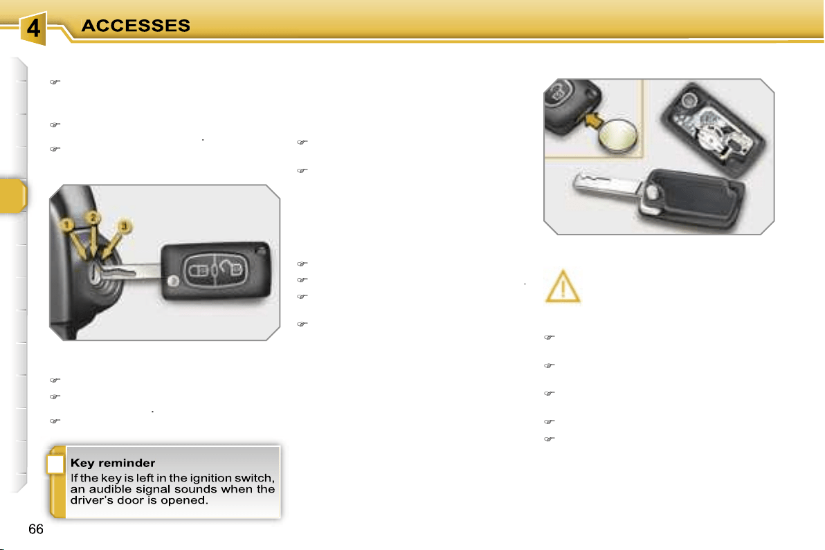
i
Starting the vehicle
Insert the key in the ignition switch.
The system recognises the starting
code.
Turn the key fully towards the fascia
to position
3 (Starting)
.
When the engine starts, release the
key.
Switching the vehicle off
Immobilise the vehicle.
Turn the key fully towards you to po-
sition
1 (Stop)
.
Remove the key from the ignition switch.
Remote control problem
Following disconnection of the vehicle
battery, replacement of the remote con-
trol battery or in the event of a remote
control malfunction, you can no longer
unlock, lock or locate your vehicle.
First of all, use the key in the lock to
unlock or lock your vehicle.
Then, reinitialise the remote control.
If the problem persists, contact a
PEUGEOT dealer as soon as possible.
Changing the battery
Battery ref.: CR1620/3 volts.
Reinitialisation
Switch off the ignition.
Turn the key to position
2 (Ignition)
.
Press the closed padlock immedia-
tely for a few seconds.
Switch off the ignition and remove
the key from the ignition switch.
The remote control is fully operational
again.
Unclip the casing using a coin at the
notch.
Slide the flat battery out of its loca-
tion.
Slide the new battery into its location
observing the original direction.
Clip the casing.
Reinitialise the remote control.
If the battery is flat, you are in-
formed by lighting of this warn-
ing light, an audible signal and
a message on the multifunction
display.
!
67

!
65
Locating your vehicle
Confidential card
Press the closed padlock to locate
your locked vehicle in a car park.
This is indicated by lighting of the cour-
tesy lights and dipped headlamps and
flashing of the direction indicators for a
few seconds.
Electronic engine immobiliser
The key contains an electronic chip
which has a special code. When the
ignition is switched on, this code must
be recognised in order for starting to be
possible.
This electronic engine immobiliser locks
the engine management system a few
minutes after the ignition is switched off
and prevents starting of the engine by
anyone who does not have the key.
Anti-theft protection
This is given to you with the duplicate
keys on delivery of your vehicle.
It bears the identification code necessary
for any work on the electronic engine im-
mobiliser by a PEUGEOT dealer.
This code is hidden by a film which
should not be removed until necessary.
In the event of a malfunction,
you are informed by lighting of
this warning light, an audible
signal and a message on the
multifunction display.
In this case, your vehicle does not start;
contact a PEUGEOT dealer as soon as
possible.

!
67

i
Starting the vehicle
Insert the key in the ignition switch.
The system recognises the starting
code.
Turn the key fully towards the fascia
to position
3 (Starting)
.
When the engine starts, release the
key.
Switching the vehicle off
Immobilise the vehicle.
Turn the key fully towards you to po-
sition
1 (Stop)
.
Remove the key from the ignition switch.
Remote control problem
Following disconnection of the vehicle
battery, replacement of the remote con-
trol battery or in the event of a remote
control malfunction, you can no longer
unlock, lock or locate your vehicle.
First of all, use the key in the lock to
unlock or lock your vehicle.
Then, reinitialise the remote control.
If the problem persists, contact a
PEUGEOT dealer as soon as possible.
Changing the battery
Battery ref.: CR1620/3 volts.
Reinitialisation
Switch off the ignition.
Turn the key to position
2 (Ignition)
.
Press the closed padlock immedia-
tely for a few seconds.
Switch off the ignition and remove
the key from the ignition switch.
The remote control is fully operational
again.
Unclip the casing using a coin at the
notch.
Slide the flat battery out of its loca-
tion.
Slide the new battery into its location
observing the original direction.
Clip the casing.
Reinitialise the remote control.
If the battery is flat, you are in-
formed by lighting of this warn-
ing light, an audible signal and
a message on the multifunction
display.
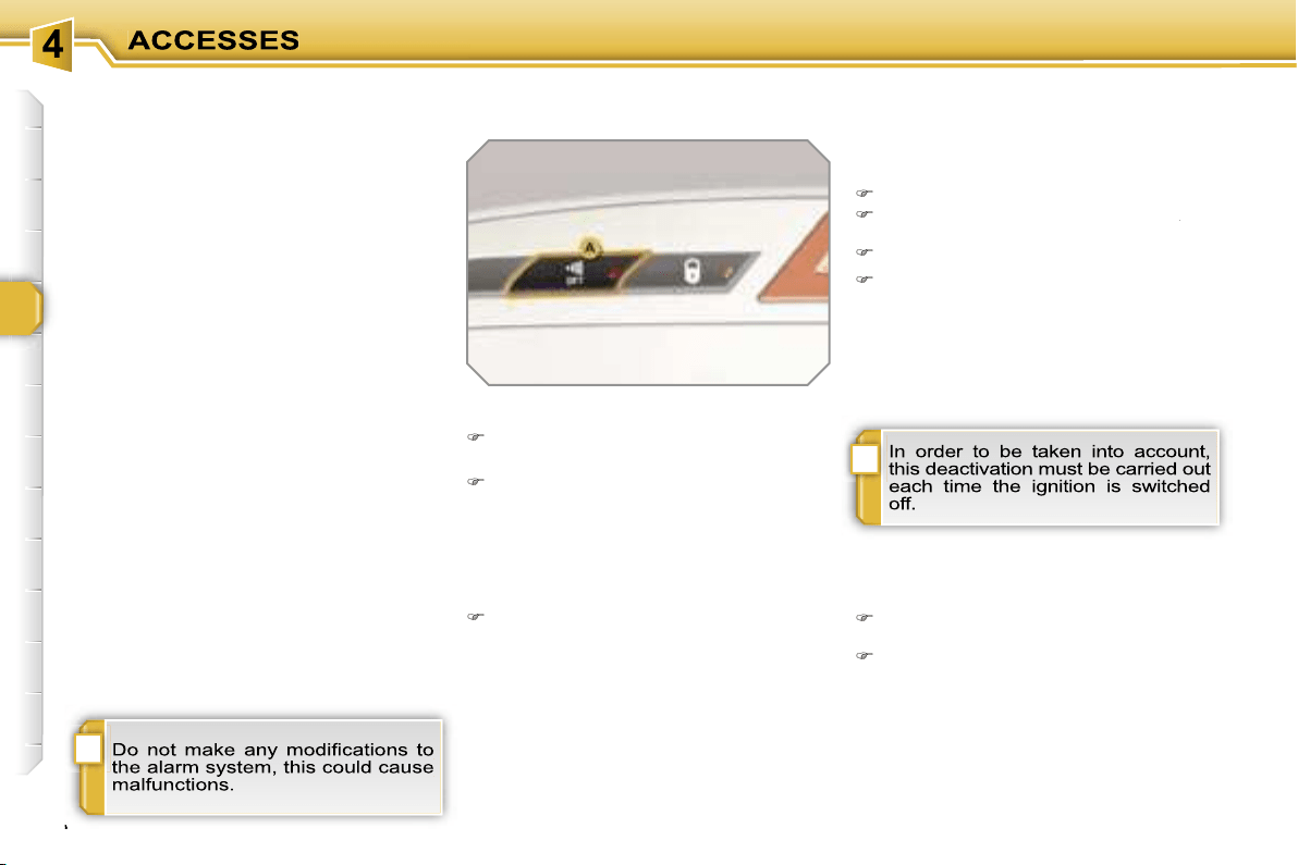
!
i
68
ALARM
System which protects and dissuades
against the theft of your vehicle. It pro-
vides two types of protection, exterior
and interior, as well as an anti-tamper
function.
Locking the vehicle with full
alarm
Reactivation of the interior
protection
Unlock the vehicle using the unloc-
king button on the remote control.
Relock the vehicle using the remote
control.
The alarm is activated again with both
types of protection; the indicator light on
button
A
switches off.
Locking the vehicle with exterior
protection alarm only
Deactivation of the interior
protection
Switch off the ignition.
Within ten seconds, press button
A
until
A
A
the indicator light is lit continuously.
Get out of the vehicle.
Lock or deadlock the vehicle using
the locking button on the remote
control.
The exterior protection alarm alone re-
mains activated; the indicator light on
button
A
flashes once per second.
Activation
Switch off the ignition and get out of
the vehicle.
Lock or deadlock the vehicle using
the locking button on the remote
control.
The alarm is activated; the indicator light
on button
A
flashes once per second.
Exterior protection
The system detects opening of the ve-
hicle.
The alarm is triggered if anyone tries to
enter the vehicle by forcing a door, the
boot or the bonnet.
Interior protection
The system detects any variation in the
volume in the passenger compartment.
The alarm is triggered if anyone breaks
a window or moves inside the vehicle.
If you wish to leave a pet in the vehicle
or a window partially open, deactivate
the interior protection.
Anti-tamper function
The system detects the putting out of
service of its components.
The alarm is triggered if anyone tries
to put the wires of the siren, the central
control or the battery out of service.
Deactivation
Unlock the vehicle using the unloc-
king button on the remote control.
The alarm is deactivated; the indicator
light on button
A
switches off.
!
69
Triggering
This is indicated by sounding of the si-
ren and flashing of the direction indica-
tors for approximately thirty seconds.
After it has been triggered, the alarm is
again operational.
Failure of the remote control
Unlock the vehicle using the key in
the driver’s door lock.
Open the door; the alarm is triggered.
Switch on the ignition; the alarm
stops.
* According to country.
Malfunction
When the ignition is switched on, light-
ing of the indicator light on button
A
for
ten seconds indicates a siren fault.
Contact a PEUGEOT dealer as soon as
possible.
Locking the vehicle without
alarm
Lock or deadlock the vehicle using
the key in the driver’s door lock.
Automatic operation*
Depending on the legislation in force in
your country, one of these cases may
occur:
- 45 seconds after the vehicle is locked
using the remote control, the alarm is
activated, regardless of the status of
the doors and boot.
- 2 minutes after the last door or the
boot is closed, the alarm is activated.
To avoid triggering the alarm on
entering the vehicle, first press the
unlocking button on the remote con-
trol.
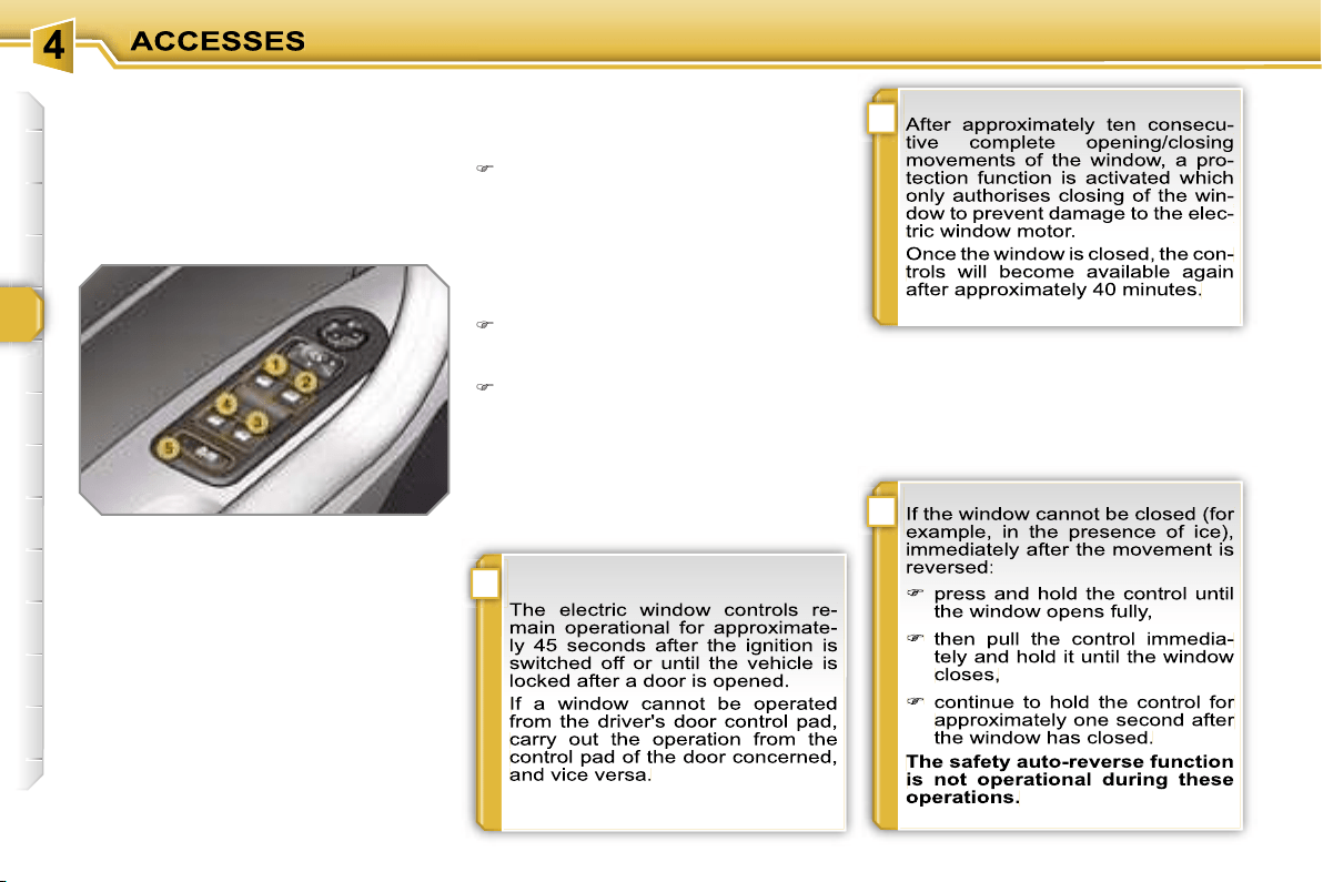
i
i
!
70
ELECTRIC WINDOWS
System intended to open or close a win-
dow manually or automatically. Fitted
with a safety auto-reverse system and
a system for deactivation in the event of
misuse of the rear controls.
1. Driver’s electric window control.
2. Passenger’s electric window
control.
3. Rear right electric window
control.
4. Rear left electric window
control.
5. Deactivation of the rear electric
window and door controls.
Safety auto-reverse
When the window rises and meets an
obstacle, it stops and partially lowers
again.
- automatic mode
Press or pull the control firmly. The
window opens or closes fully when
the control is released.
Pressing the control again stops the
movement of the window.
One-touch electric windows
There are two options:
- manual mode
Press or pull the control gently. The
window stops when the control is re-
leased.
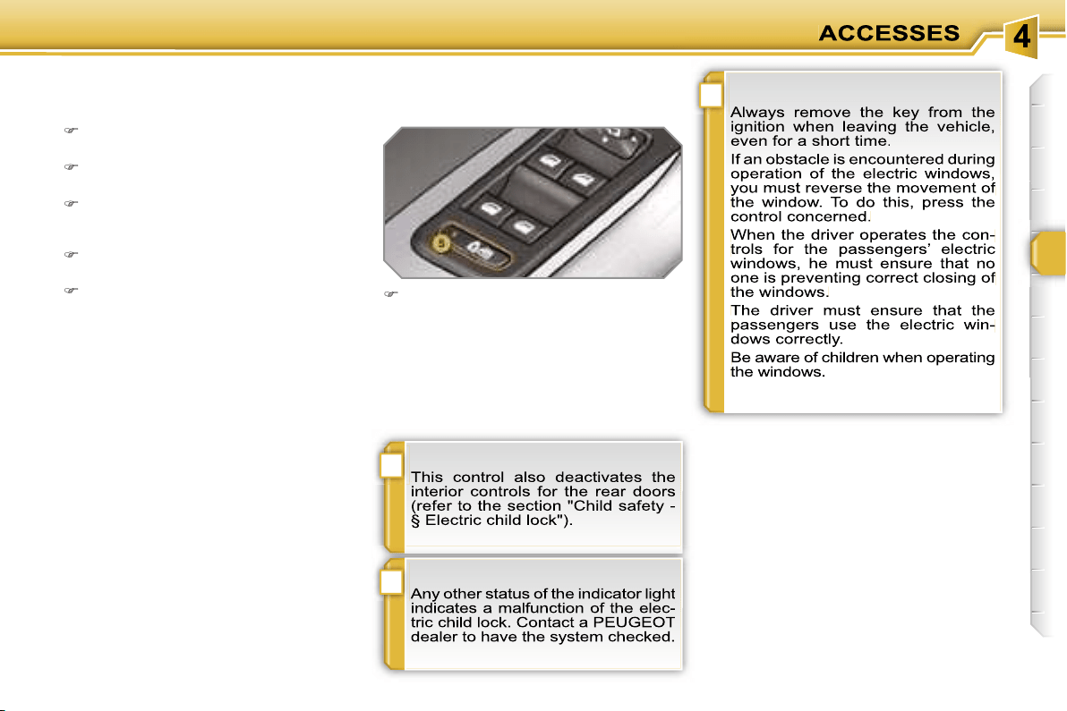
!
i
!
71
Reinitialisation
If a window does not rise automatically,
its operation must be reinitialised:
pull the control until the window
stops,
release the control and pull it again
until the window closes fully,
continue to hold the control for ap-
proximately one second after the
window has closed,
press the control to lower the window
automatically to the low position,
when the window has reached the
low position, press the control again
for approximately one second.
The safety auto-reverse function is
not operational during these opera-
tions.
Deactivation of the rear electric
window and door controls
For the safety of your children, press
control
5
to deactivate the rear elec-
tric window controls regardless of
their position.
Indicator light on, the rear controls are
deactivated.
Indicator light off, the rear controls are
activated.
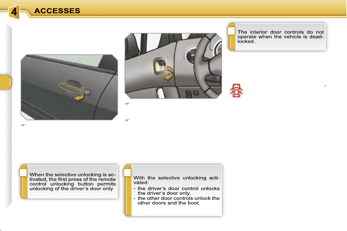
!
i
i
72
DOORS
Opening
From outside
After unlocking the vehicle comple-
tely using the remote control or the
key, pull the door handle.
From inside
Pull the front door control to open the
door; this unlocks this vehicle com-
pletely.
Pull the rear door control to open the
door; this unlocks the door concer-
ned only.
Closing
When a door is not closed correctly:
-
when the engine is running
,
this warning light comes on,
accompanied by a message
on the multifunction display
for a few seconds,
-
when the vehicle is moving
(speed
higher than 6 mph (10 km/h)), this
warning light comes on, accompanied
by an audible signal and a message
on the multifunction display for a few
seconds.
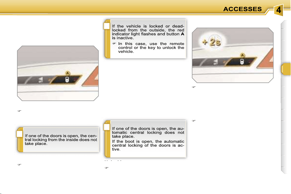
i
!
i
73
Manual centralised control
System which provides full manual
locking or unlocking of the doors from
the inside.
Locking
Press button
A
to lock the vehicle.
The red indicator light on the button
comes on.
Automatic centralised control
System which provides full automatic
locking or unlocking of the doors and
boot while driving.
You can activate or deactivate this func-
tion.
Activation
Press button
A
for more than two
seconds.
A confirmation message appears on the
multifunction display, accompanied by
an audible signal.
Unlocking
Above 6 mph (10 km/h), press but-
ton
A
to unlock the doors and boot
temporarily.
Unlocking
Press button
A
again to unlock the
vehicle.
The red indicator light on the button
switches off.
Locking
When the speed exceeds 6 mph
(10 km/h), the doors and boot lock au-
tomatically.
Deactivation
Press button
A
again for more than
two seconds.
A confirmation message appears on the
multifunction display, accompanied by
an audible signal.

i
74
Emergency control
System which locks or unlocks the
doors mechanically in the event of a
malfunction of the battery or of the cen-
tral locking.
Insert the key in the lock, located on
the edge of the door, then turn it
one
eighth of a turn
.
Opening
After unlocking the vehicle comple-
tely using the remote control or the
key, pull the handle and raise the
tailgate.
BOOT
-
when the engine is running
,
this warning light comes on,
accompanied by a message
on the multifunction display
for a few seconds,
-
when the vehicle is moving
(speed
above 6 mph (10 km/h)), this warning
light comes on, accompanied by an
audible signal and a message on the
multifunction display for a few seconds.
Tailgate release
System for mechanical unlocking of the
boot in the event of a battery or central
locking malfunction.
Unlocking
Fold back the rear seats to gain
access to the lock
from inside the
boot.
Insert a small screwdriver into hole
A
of the lock to unlock the tailgate.
Locking the driver’s door
Insert the key in the lock, then turn it
to the right.
Unlocking the driver’s door
Insert the key in the lock, then turn it
to the left.
Locking the front and rear
passenger doors
Unlocking the front and rear
passenger doors
Pull the interior door opening con-
trol.
Closing
Lower the tailgate using the interior
grab handle.
If the tailgate is not closed correctly:
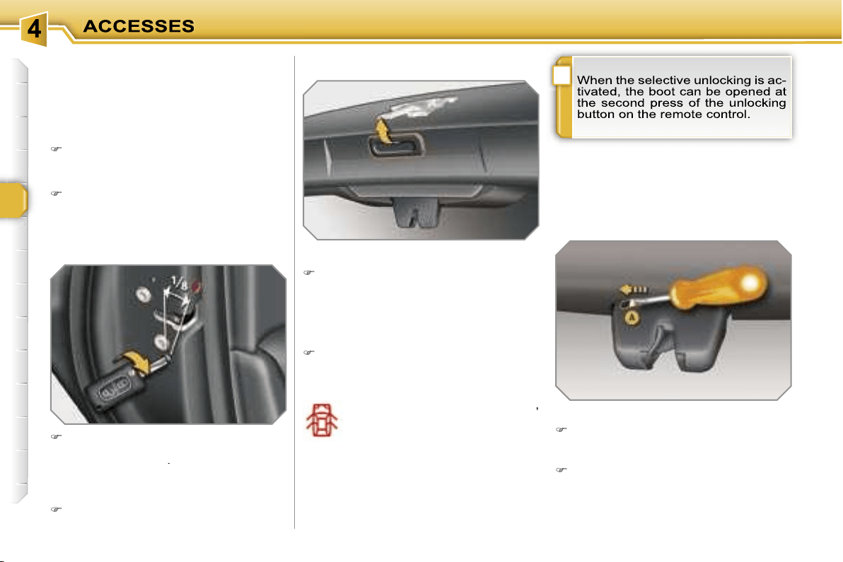
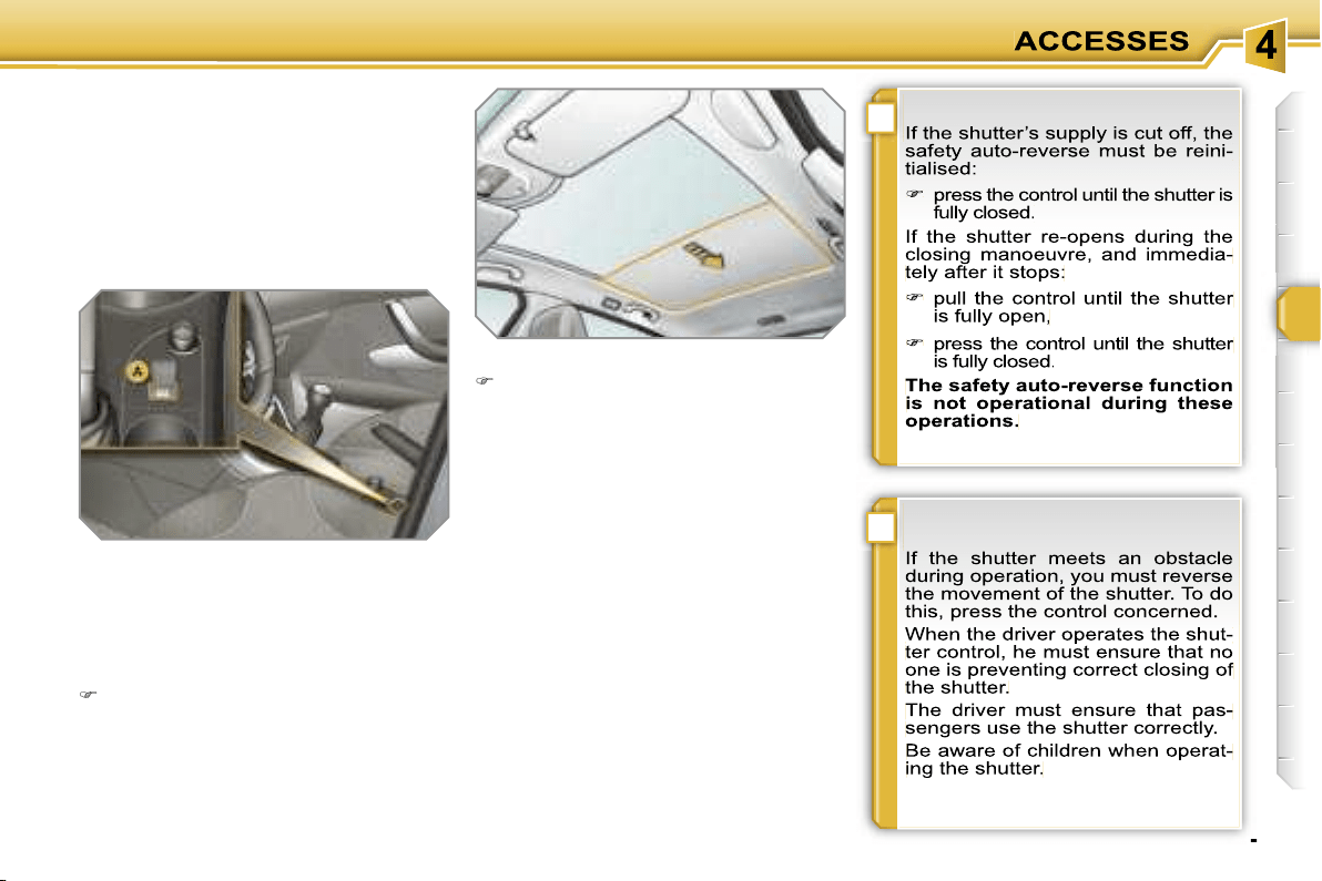
!
i
75
GLASS PANORAMIC ROOF
Component which has a tinted glass
panoramic surface to increase the light
and visibility in the passenger compart-
ment. Fitted with an electric shutter in
several sections to improve tempera-
ture and noise related comfort.
- manual mode
Pull or press control
A
gently.
The shutter stops when you release
the control.
- automatic mode
Pull or press control
A
firmly.
One press opens or closes the shutter
completely.
Pressing the control again stops the
shutter.
Safety auto-reverse
In automatic mode and at the end of its
travel, if the shutter meets an obstacle
while closing it stops and moves back
slightly.
One-touch electric shutter
There are two options for opening and
closing:
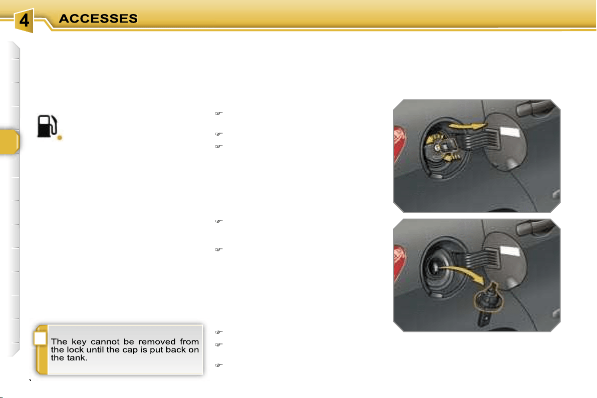
i
76
FUEL TANK
Capacity of the tank: approximately
60 litres.
To fill the tank safely:
it is essential that the engine is
switched off,
open the fuel filler flap,
insert the key in the cap, then turn it
to the left,
When filling is complete:
put the cap back in place,
turn the key to the right, then remove
it from the cap,
close the flap.
remove the cap and secure it on the
hook, located on the inside of the
flap,
fill the tank, but
do not continue
after the 3rd cut-off of the nozzle
;
this could cause malfunctions.
Low fuel level
Filling
A label affixed to the inside of the flap
reminds you of the type of fuel to be
used according to your engine.
Operating fault
A fuel gauge malfunction is indicated by
the return of the fuel level indicator nee-
dle to zero.
Contact a PEUGEOT dealer.
When the fuel tank minimum
level is reached, this warning
light comes on on the instru-
ment panel, accompanied by
an audible signal and a message on the
multifunction display.
You have enough fuel left to drive
approximately 30 miles (50 km).
If you run out of fuel, refer to the "Practi-
cal information» section also.
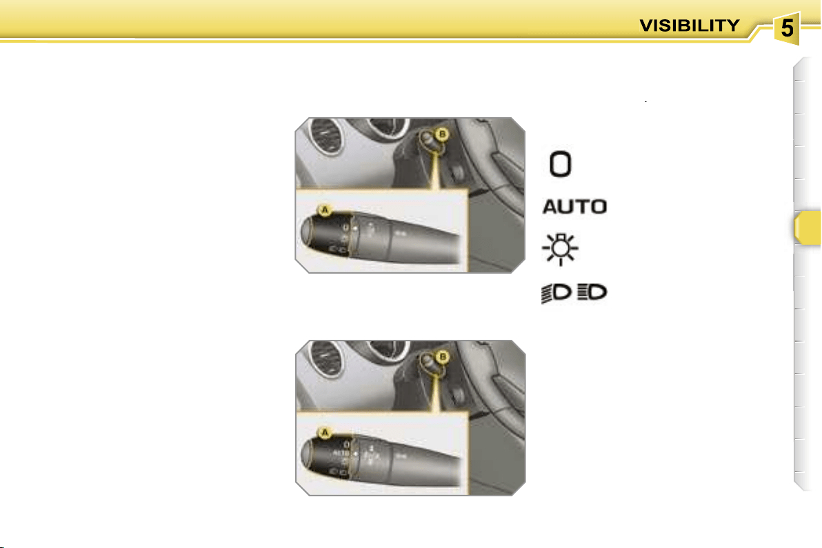
77
LIGHTING CONTROLS
System for selection and control of the
various front and rear lights providing
the vehicle’s lighting.
Main lighting
The various front and rear lights of the
vehicle are designed to adapt the driv-
er’s visibility progressively in relation to
the climatic conditions:
- side lights, to be seen,
- dipped headlamps to see without daz-
zling other drivers,
- main beam headlamps to see clearly
when the road is clear,
- directional headlamps for improved
visibility when cornering.
Additional lighting
Other lights are installed to fulfil the re-
quirements of particular driving condi-
tions:
- rear fog lamps to be seen from a dis-
tance,
- front fog lamps for even better visibil-
ity,
- daytime lights to be seen during the
day.
Programming
Various automatic lighting control
modes are also available according to
the following options:
- follow-me-home lighting,
- automatic lighting,
- directional lighting.
Model without AUTO lighting
Model with AUTO lighting
automatic switching on of
the lights,
Manual controls
The lighting commands are issued di-
rectly by the driver by means of the ring
A
and the lever
B
.
A.
main lighting mode selection ring,
with:
lights off,
side lights only,
B.
lever for inversion of the lights by
pulling: dipped headlamps/main
beam headlamps.
In the lights off and side lights modes,
the driver can switch on the main beam
headlamps directly ("headlamp flash")
for as long as he pulls the lever.
dipped headlamps or main
beam headlamps.
Displays
Lighting of the corresponding indicator
light on the instrument panel confirms
the selective switching on of the lighting
selected.
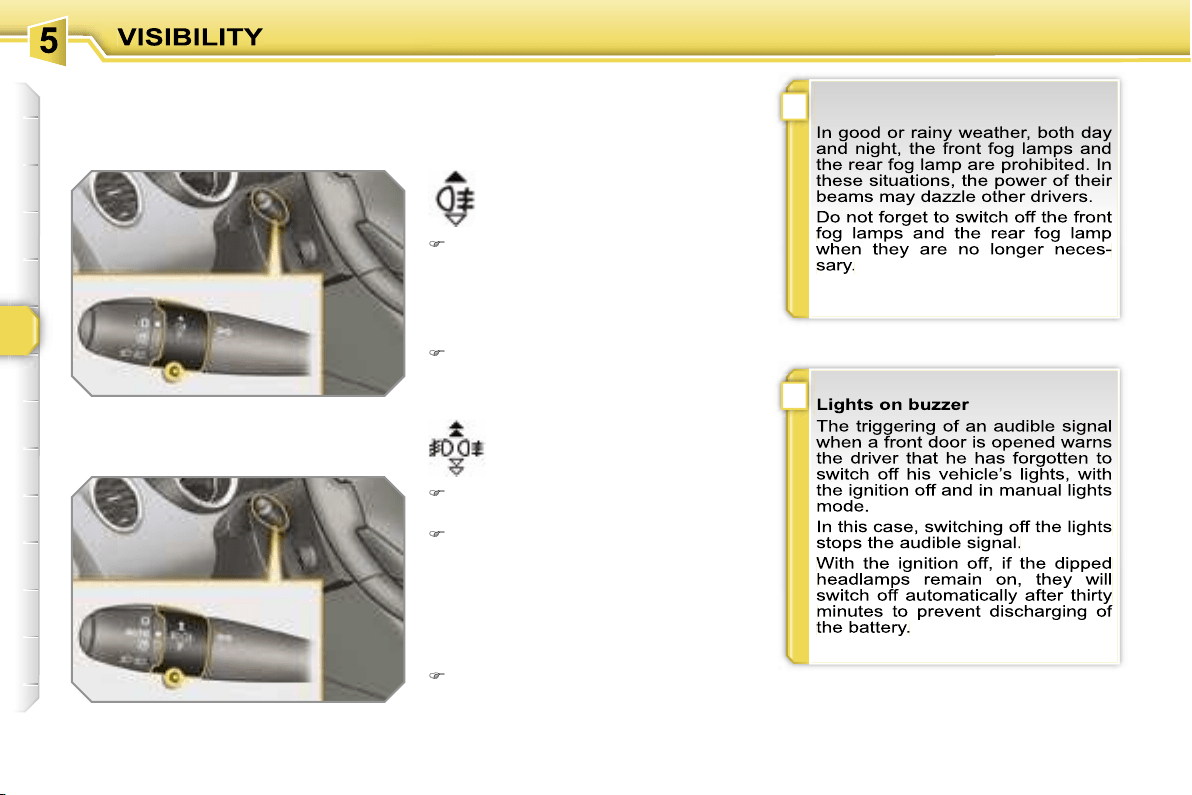
!
i
78
Model with rear fog lamp only
rear fog lamp
To switch on the fog lamp, turn the
ring
C
forwards.
When the lights are switched off auto-
matically (with AUTO model), the fog
lamp and the dipped headlamps will re-
main on.
To switch off all of the lights, turn the
ring
C
rearwards.
Model with front and rear fog lamps
front and rear fog lamps
To switch on the fog lamps, turn the
ring
C
forwards.
To switch off the rear fog lamp, turn
the ring
C
rearwards twice in succes-
sion.
When the lights are switched off auto-
matically (with AUTO model) or when
the dipped headlamps are switched off
manually, the fog lamps and the side
lights will remain on.
Turn the ring rearwards to switch
off the fog lamps, the side lights will
then switch off.
C.
fog lamps selection ring.
The fog lamps operate with the dipped
and main beam headlamps.

i
i
79
Follow-me-home lighting
The temporary maintaining of the
dipped headlamps lighting after the ve-
hicle’s ignition has been switched off
makes the driver’s exit easier when the
light is poor.
Switching on
With the ignition off, "flash" the head-
lamps using the lever
B
.
A second "headlamp flash" switches
the function off again.
Switching off
The follow-me-home lighting switches
off automatically after a set time.
Daytime lights
On vehicles fitted with daytime lights,
the corresponding lights comes on
when the vehicle is started*.
* According to country.
The instruments and controls (instru-
ment panel, multifunction display, air
conditioning control panel, ...) are not
lit, except on switching to the automatic
switching on of the lights mode or when
the lights are switched on manually.
Exterior welcome lighting
The remote switching on of the lights
makes your approach to the vehicle
easier in poor light when in automatic
switching on of the lights mode.
Switching on
Press the open padlock on the re-
mote control.
The dipped headlamps and the side
lights come on; your vehicle is also
unlocked.
Switching off
The exterior welcome lighting switches
off automatically after a set time, when
the ignition is switched on or on locking
the vehicle.
Programming
The function is activated or
deactivated via the multi-
function display configura-
tion menu.
Programming
The duration of maintaining
of the lighting is selected
via the multifunction dis-
play configuration menu.
In countries in which this function is im-
posed by regulations*, it is activated by
default.
The side lights and the number plate
lights are also switched on.
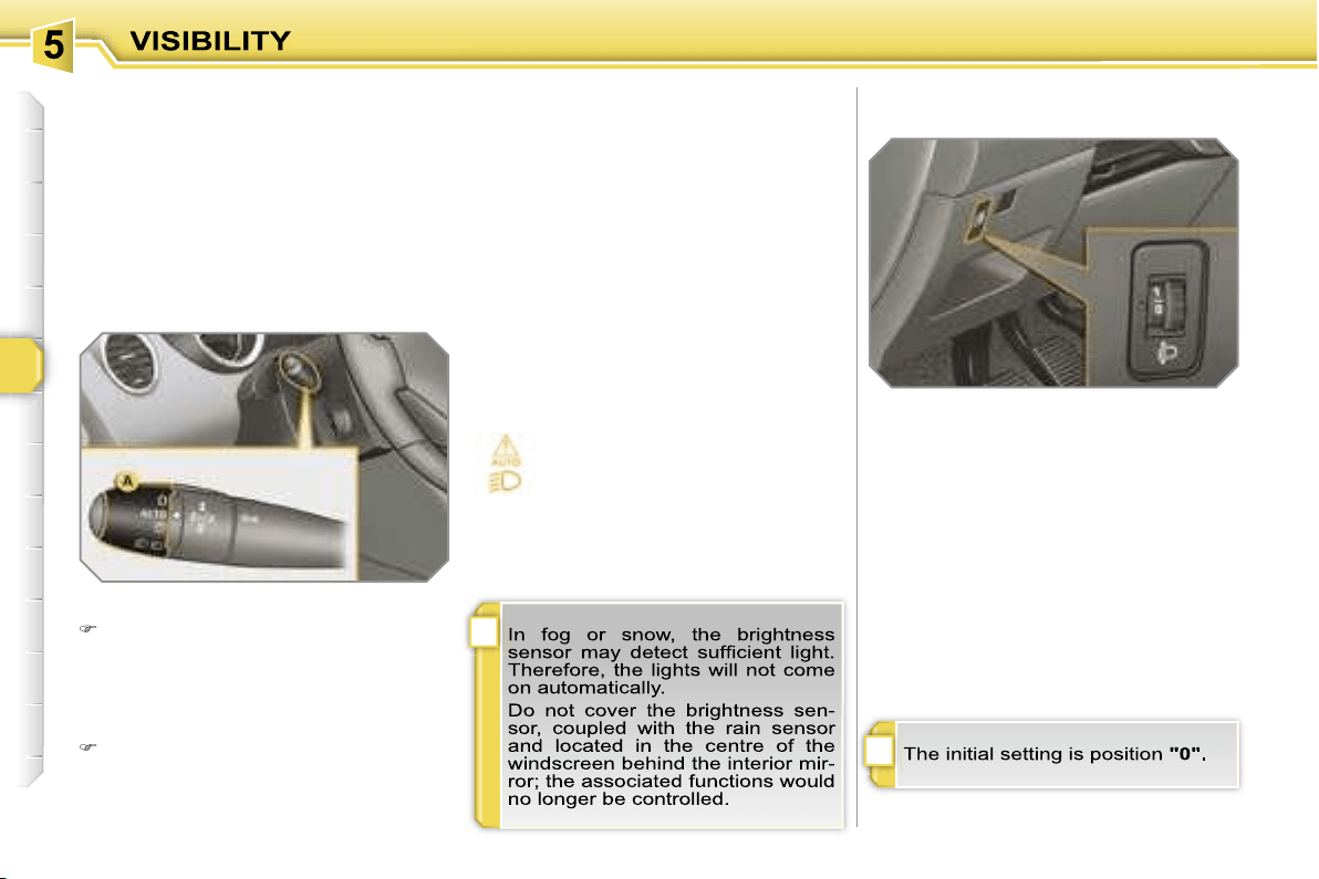
!
i
80
Coupling with the "Follow-me-
home" lighting
Association with the automatic lighting
provides the "follow-me-home" lighting
with the following additional options:
- selection of the duration of maintaining
of the lighting for 15, 30 or 60 seconds
in the vehicle parameters on the multi-
function display configuration menu,
- automatic activation of "follow-me-
home" lighting when automatic light-
ing is in operation.
Automatic lighting
The side lights and dipped headlamps
are switched on automatically, without
any action on the part of the driver,
when a low level of external light is de-
tected or in certain cases of activation
of the windscreen wipers.
As soon as the brightness returns to a
sufficient level or after the windscreen
wipers are switched off, the lights are
switched off automatically.
Activation
Turn ring
A
to the
"AUTO"
position.
The automatic lighting is accompa-
nied by a message on the multifunc-
tion display.
Deactivation
Turn ring
A
to a position other than
"AUTO"
. Deactivation is accompa-
nied by a message on the multifunc-
tion display.
Operating fault
In the event of a malfunction
of the brightness sensor, the li-
ghts come on, this warning light
is displayed on the instrument
panel and/or a message appears on the
multifunction display, accompanied by
an audible signal.
In this case, contact a PEUGEOT dealer.
MANUAL HEADLAMP
ADJUSTMENT
To avoid causing a nuisance to other
road users, the height of the halogen
headlamps should be adjusted in rela-
tion to the load in the vehicle.
0.
1 or 2 people in the front seats.
-.
3 people.
1.
5 people.
2.
5 people + maximum authorised
load.
3.
Driver + maximum authorised load.
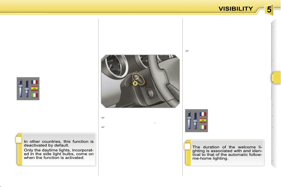
i
i
79
Follow-me-home lighting
The temporary maintaining of the
dipped headlamps lighting after the ve-
hicle’s ignition has been switched off
makes the driver’s exit easier when the
light is poor.
Switching on
With the ignition off, "flash" the head-
lamps using the lever
B
.
A second "headlamp flash" switches
the function off again.
Switching off
The follow-me-home lighting switches
off automatically after a set time.
Daytime lights
On vehicles fitted with daytime lights,
the corresponding lights comes on
when the vehicle is started*.
* According to country.
The instruments and controls (instru-
ment panel, multifunction display, air
conditioning control panel, ...) are not
lit, except on switching to the automatic
switching on of the lights mode or when
the lights are switched on manually.
Exterior welcome lighting
The remote switching on of the lights
makes your approach to the vehicle
easier in poor light when in automatic
switching on of the lights mode.
Switching on
Press the open padlock on the re-
mote control.
The dipped headlamps and the side
lights come on; your vehicle is also
unlocked.
Switching off
The exterior welcome lighting switches
off automatically after a set time, when
the ignition is switched on or on locking
the vehicle.
Programming
The function is activated or
deactivated via the multi-
function display configura-
tion menu.
Programming
The duration of maintaining
of the lighting is selected
via the multifunction dis-
play configuration menu.
In countries in which this function is im-
posed by regulations*, it is activated by
default.
The side lights and the number plate
lights are also switched on.

!
i
80
Coupling with the "Follow-me-
home" lighting
Association with the automatic lighting
provides the "follow-me-home" lighting
with the following additional options:
- selection of the duration of maintaining
of the lighting for 15, 30 or 60 seconds
in the vehicle parameters on the multi-
function display configuration menu,
- automatic activation of "follow-me-
home" lighting when automatic light-
ing is in operation.
Automatic lighting
The side lights and dipped headlamps
are switched on automatically, without
any action on the part of the driver,
when a low level of external light is de-
tected or in certain cases of activation
of the windscreen wipers.
As soon as the brightness returns to a
sufficient level or after the windscreen
wipers are switched off, the lights are
switched off automatically.
Activation
Turn ring
A
to the
"AUTO"
position.
The automatic lighting is accompa-
nied by a message on the multifunc-
tion display.
Deactivation
Turn ring
A
to a position other than
"AUTO"
. Deactivation is accompa-
nied by a message on the multifunc-
tion display.
Operating fault
In the event of a malfunction
of the brightness sensor, the li-
ghts come on, this warning light
is displayed on the instrument
panel and/or a message appears on the
multifunction display, accompanied by
an audible signal.
In this case, contact a PEUGEOT dealer.
MANUAL HEADLAMP
ADJUSTMENT
To avoid causing a nuisance to other
road users, the height of the halogen
headlamps should be adjusted in rela-
tion to the load in the vehicle.
0.
1 or 2 people in the front seats.
-.
3 people.
1.
5 people.
2.
5 people + maximum authorised
load.
3.
Driver + maximum authorised load.
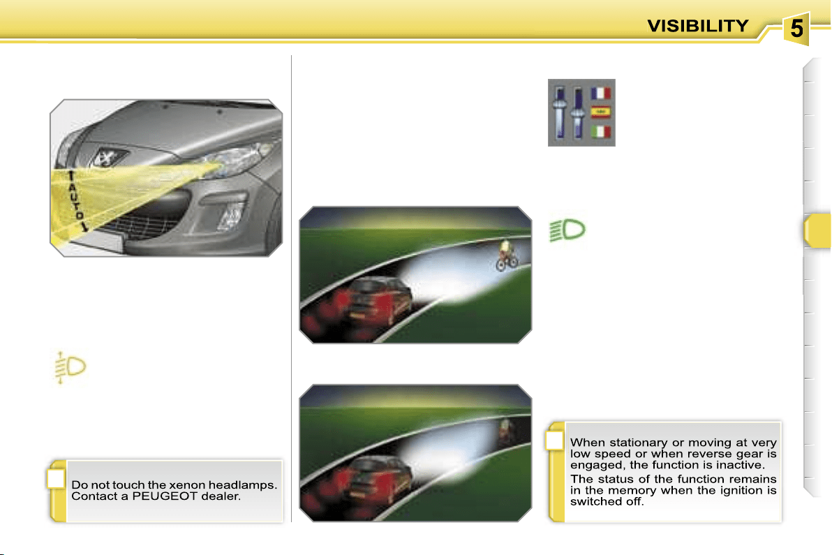
!
i
81
DIRECTIONAL LIGHTING
When the dipped or main beam head-
lamps are on, this function enables the
light beam to follow the direction of the
road.
The use of this function, coupled with
the xenon headlamps only, considera-
bly improves the quality of your lighting
when cornering.
with directional lighting
without directional lighting
Programming
Operating fault
The function is activated or
deactivated via the multi-
function display configura-
tion menu.
If a malfunction occurs, this
warning light flashes on the in-
strument panel, accompanied
by a message on the multifunc-
tion display.
Contact a PEUGEOT dealer.
AUTOMATIC ADJUSTMENT
OF THE DIRECTIONAL
HEADLAMPS
In order to avoid causing a nuisance to
other road users, this system corrects
the height of the xenon headlamps beam
automatically and when stationary, in re-
lation to the load in the vehicle.
If a malfunction occurs, this
warning light and/or the service
warning light is displayed on the
instrument panel, accompanied
by an audible signal and a message on
the multifunction display.
The system then places your head-
lamps inb the lowest position.
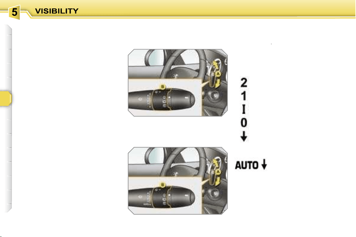
82
WIPER CONTROLS
System for selection and control of the
various front and rear wiping modes for
the elimination of rain and cleaning.
The vehicle’s various front and rear wip-
ers are designed to improve the driver’s
visibility progressively in relation to the
climatic conditions.
Manual controls
The wiper commands are issued direct-
ly by the driver by means of the lever
A
and the ring
B
.
Model with intermittent wiping
Model with AUTO wiping
fast (heavy rain),
normal (moderate rain),
intermittent (proportional to
the speed of the vehicle),
automatic, then single
wipe (see following
page).
park,
single wipe (press down-
wards),
Programming
Various automatic wiper control modes
are also available according to the fol-
lowing options:
- automatic wiping for the windscreen
wipers,
- rear wiping on engaging reverse
gear.
Windscreen wipers
A.
wiping speed selection lever:
or
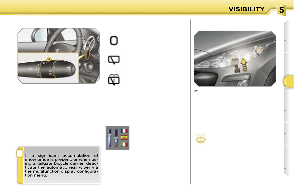
!
83
Windscreen and headlamp wash
B.
rear wiper selection ring:
park,
intermittent wipe,
wash-wipe (set duration).
Reverse gear
When reverse gear is engaged, the
rear wiper will come into operation if the
windscreen wipers are operating.
Programming
Pull the windscreen wiper stalk to-
wards you. The windscreen wash
then the windscreen wipers operate
for a fixed period.
If the dipped headlamps are on,
the
headlamp washers operate at the same
time.
Rear wiper
The function is activated or
deactivated via the multi-
function display configura-
tion menu.
This function is activated
by default.
Screenwash/headlamp
wash low
In the case of vehicles fitted with
headlamp washers, when the
minimum level of the reservoir is
reached, this warning light and/or
the service warning light is displayed on
the instrument panel, accompanied by an
audible signal and a message on the mul-
tifunction display.
Next time you stop, fill the screenwash/
headlamp wash reservoir.
The warning light is displayed when the ig-
nition is switched on, or every time the stalk
is operated, until the reservoir is filled.

!
i
i
84
Special position of the
windscreen wipers
Automatic windscreen wiping
The windscreen wipers operate auto-
matically, without any action on the part
of the driver, if rain is detected (sensor
behind the interior mirror), adapting their
speed to the intensity of the rainfall.
Activation
This is controlled manually by the dri-
ver by pushing lever
A
to the
"AUTO"
position.
It is accompanied by a message on the
multifunction display.
In the minute following switching off of
the ignition, any action on the stalk po-
sitions the wipers in the centre of the
windscreen.
This action enables you to position the
wiper blades for winter parking, clean-
ing or replacement.
To park the wipers after this has been
done, switch on the ignition and operate
the stalk.
Switching off
This is controlled manually by the driver
by moving lever
A
upwards and return-
ing it to position
"0"
.
It is accompanied by a message on the
multifunction display.
Operating fault
If an automatic wiping malfunction oc-
curs, the wipers will operate in intermit-
tent mode.
Contact a PEUGEOT dealer to have the
system checked.
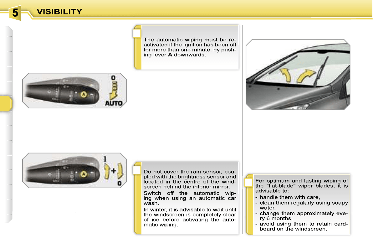
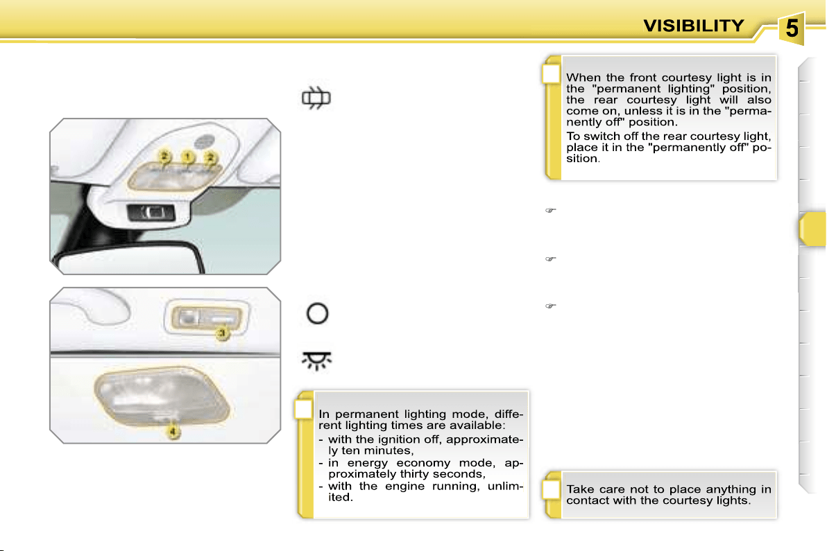
i
i
!
85
COURTESY LIGHTS
Selection and control of the various
passenger compartment lights.
1. Front courtesy light
2. Map reading lights
3. Rear side reading lights
4. Rear courtesy light
Front and rear courtesy lights
In this position, the courtesy li-
ght comes on gradually:
Map reading lights
With the ignition on, press the cor-
responding switch.
- when the vehicle is unlocked,
- when the key is removed from the ig-
nition,
- when a door is opened,
- when the remote control locking button is
activated, in order to locate your vehicle.
It switches off gradually:
- when the vehicle is locked,
- when the ignition is switched on,
- 30 seconds after the last door is closed.
Permanently off.
Permanent lighting.
Rear side reading lights
With the ignition on, the first press of
the corresponding switch switches
on the reading light concerned in
permanent lighting mode.
Following a second press, it comes on:
- when the vehicle is unlocked,
- when the key is removed from the
ignition,
- when a door is opened,
- when the remote control locking
button is pressed, in order to locate
your vehicle.
It switches off gradually:
- when the vehicle is locked,
- when the ignition is switched on,
- 30 seconds after the last door is
closed.
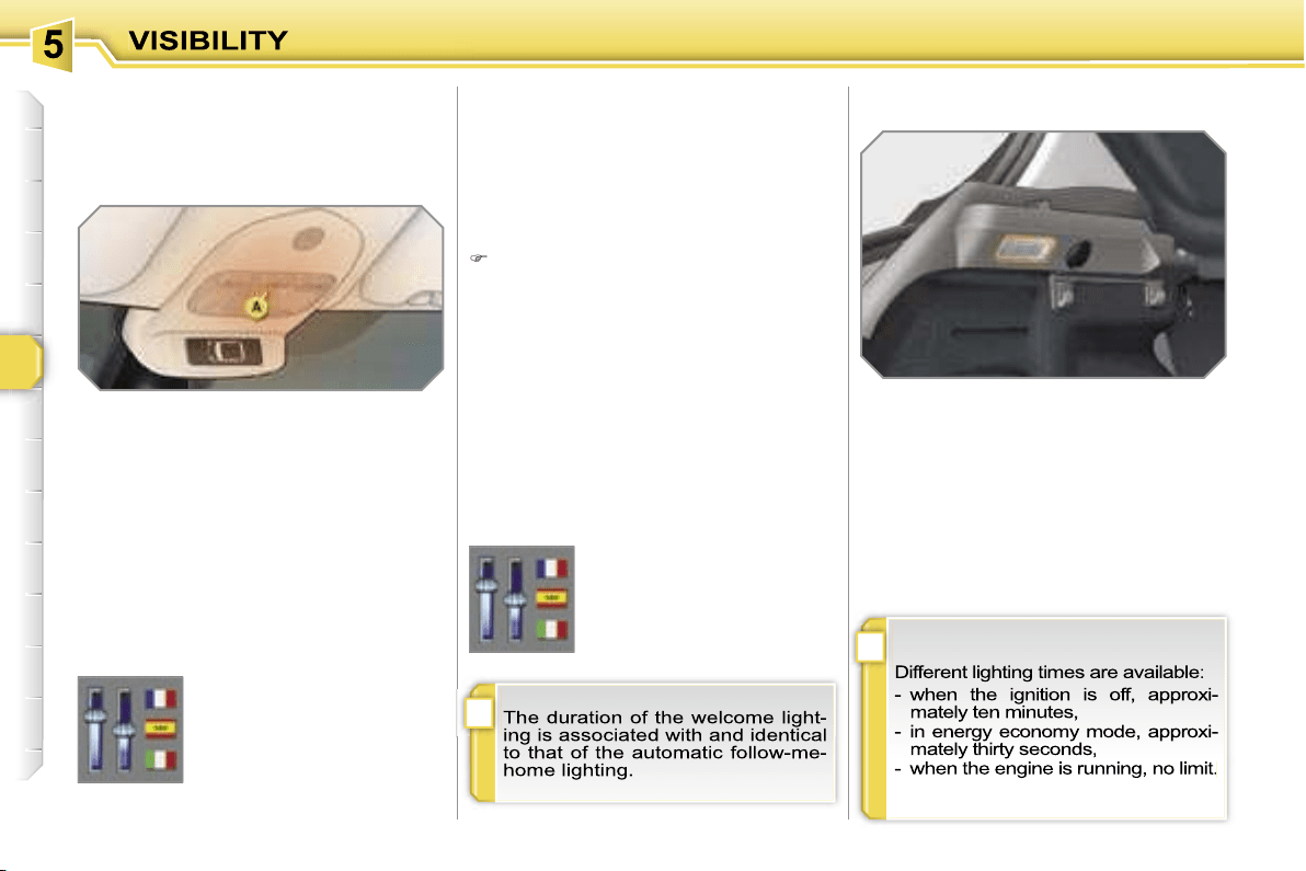
i
i
86
AMBIENT LIGHTING
This comes on automatically when the
boot is opened and switches off auto-
matically when the boot is closed.
INTERIOR WELCOME LIGHTING BOOT LIGHTING
The remote switching on of the passenger
compartment lighting makes your approach
to the vehicle easier in poor light when in
automatic switching on of the lights mode.
Switching on
Press the open padlock on the re-
mote control.
The front and rear door sill lighting,
the footwell lighting and the courtesy
lights come on; your vehicle is also
unlocked.
Switching off
The interior welcome lighting switches
off automatically after a set time or when
one of the doors is opened.
Programming
The dimmed passenger compartment
lighting improves visibility in the vehicle
when the light is poor.
Switching on
At night, the footwell lighting and the
front courtesy light ambient lamp
A
come on automatically when the side
lights are switched on.
Switching off
The ambient lighting switches off auto-
matically when the dipped headlamps
are switched off.
Programming
The function is activated or
deactivated via the multi-
function display configura-
tion menu.
This function is activated
by default.
The duration of maintaining
of the lighting is selected
via the multifunction dis-
play configuration menu.
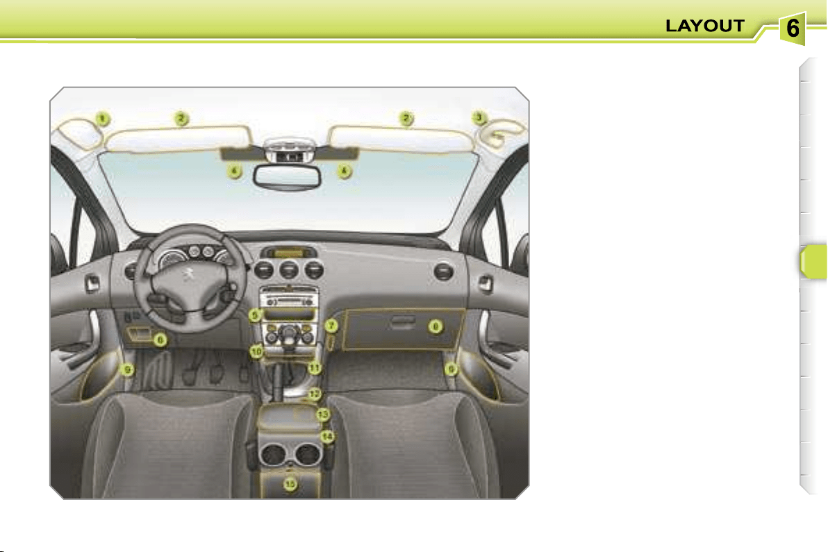
87
INTERIOR LAYOUT
1. Spectacles storage
2. Sun visor
(see details on following page)
3. Grab handle with coat hook
4. Toll card/car park ticket
windows
(see details on following page)
5. Storage compartment
6. Storage compartment
7. Bag hook
8. Glove box with light
(see details on following page)
9. Door trays
10. Ashtray with light
(see details on following page)
11. Storage compartment with
non-slip carpet
12. Lighter/12 V accessories socket
(see details on following page)
13. Can holder
14. Front armrest
(see details on following page)
15. Storage box
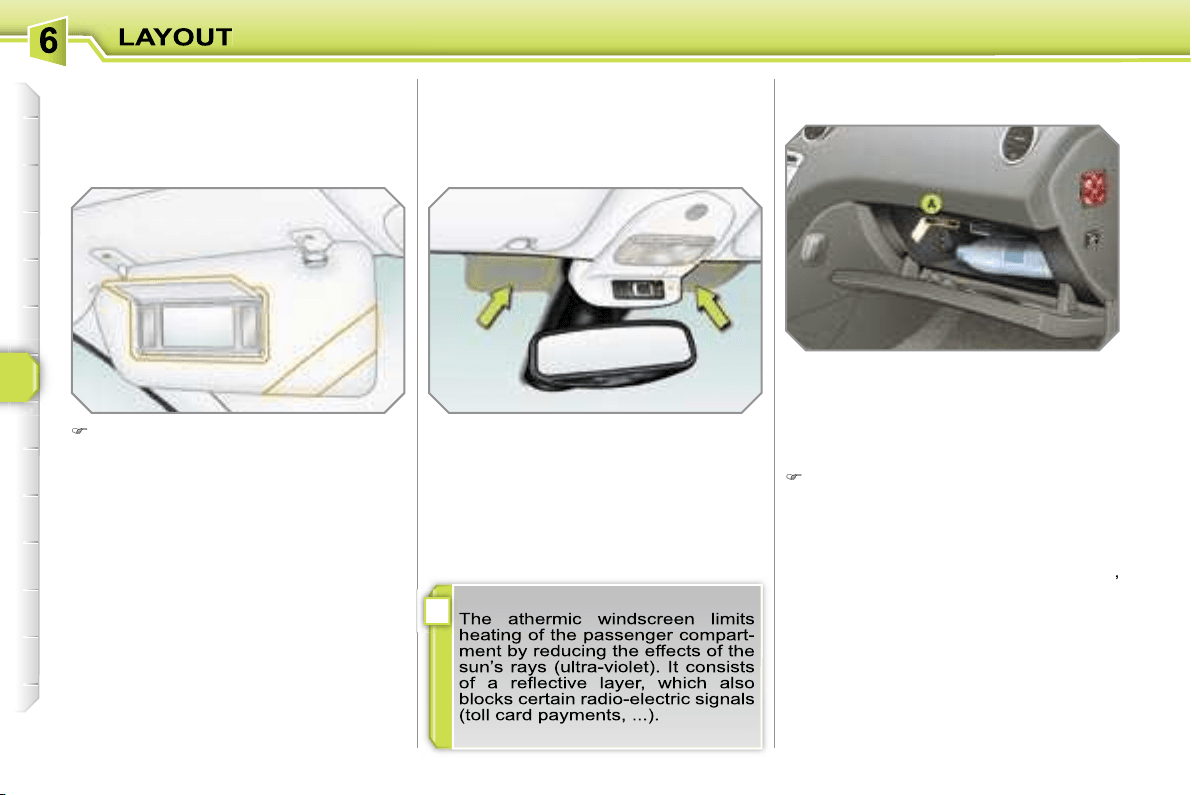
i
88
GLOVE BOX WITH LIGHT
This has areas for storing a bottle of wa-
ter, the vehicle’s handbook, ...
Its lid has areas for storing a pen, a pair
of spectacles, tokens, cards, a can, fra-
grance cartridges, ...
To open the glove box, raise the handle.
The light comes on when the lid is
opened.
If the vehicle is fitted with air condition-
ing, it provides access to the air vent
A
,
which can be opened or closed, distri-
buting the same conditioned air as the
vents in the passenger compartment.
SUN VISOR
Component which protects against
sunlight from the front or the side, also
equipped with an illuminated courtesy
mirror.
With the ignition on, raise the con-
cealing flap; the mirror is lit automati-
cally.
This sun visor is also equipped with a
ticket holder.
TOLL CARD/CAR PARK TICKET
WINDOWS
Facility for affixing toll cards and/or car
park tickets.
These windows are located on each
side of the base of the interior mirror.
They are two non-reflective areas of the
athermic windscreen.
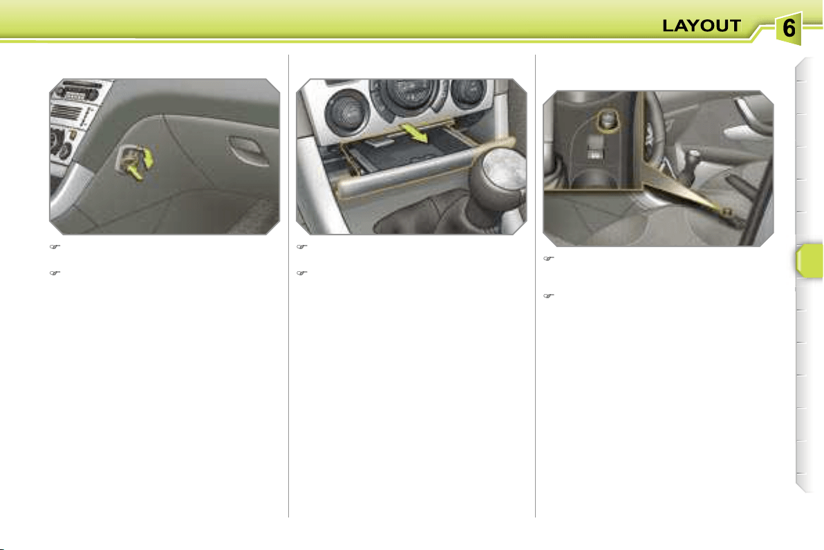
89
LIGHTER/12 V ACCESSORIES
SOCKET
To use the lighter, press it in and wait
a few seconds until it pops out auto-
matically.
To connect a 12 V accessory (max
power: 100 Watts), remove the light-
er and connect a suitable adaptor.
ASHTRAY WITH LIGHT
Pull the drawer to gain access to the
ashtray.
To empty the ashtray, after opening,
press the tab and remove the ash-
tray.
BAG HOOK
Press the lower part of the hook to
unfold it.
Hang the strap of your bag on the
hook to secure it.
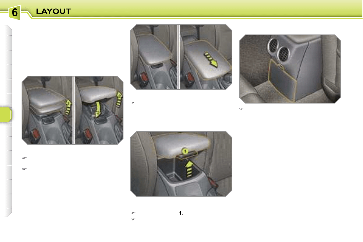
90
FRONT ARMREST
Comfort and storage device for the driver
and front passenger.
The height and longitudinal position of
the armrest cover can be adjusted for
greater comfort.
Height adjustment
Raise the cover to the required posi-
tion (low, intermediate or high).
If you raise the cover slightly beyond
the high position, guide it when low-
ering it to the low position.
STORAGE BOX
To empty the box, after opening,
press the tab and remove it.
Storage
The armrest’s compartment can hold up
to 6 CDs.
Raise the lever
1
.
Raise the cover fully.
Longitudinal adjustment
Slide the cover fully forwards or rear-
wards.
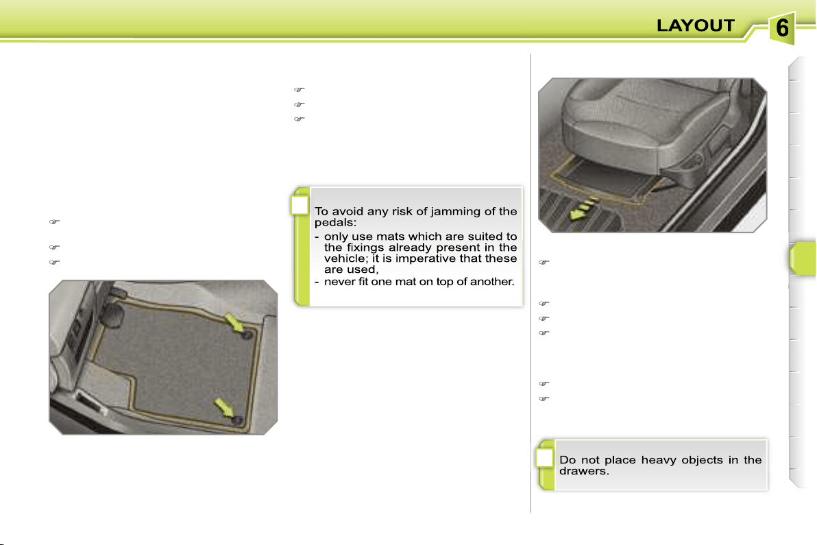
!
!
91
MAT
Removable component which protects
the carpet against exterior dirt.
Refitting
To refit the mat on the driver’s side:
position the mat correctly,
refit the fixings by pressing,
check that the mat is secured cor-
rectly.
Fitting
When fitting the mat for the first time,
use only the fixings provided in the wal-
let attached.
Removal
To remove the mat on the driver’s side:
move the seat as far back as pos-
sible,
unclip the fixings,
remove the mat.
STORAGE DRAWERS*
Opening
Raise the front of the drawer and pull it.
* Except on electric seat.
Removal
Bring the drawer to the end of its travel.
Press the ends of the slides.
Raise the drawer and pull it fully.
Refitting
Engage the drawer in its slides.
At the end of its travel, press on the
top of the drawer to secure it.
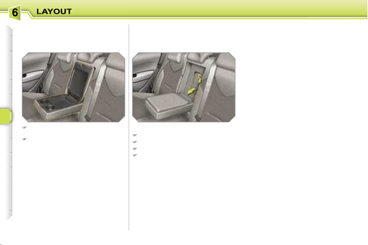
92
REAR ARMREST
Comfort and storage device for the rear
passengers.
SKI FLAP
Device for storing and transporting long
objects.
Opening
Lower the rear armrest.
Pull the flap handle downwards.
Lower the flap.
Load the objects from inside the boot.
Lower the rear armrest for a more
comfortable position.
Raise the cover to gain access to its
storage compartment.
This has a storage tray, two can holders
and two pen holders.
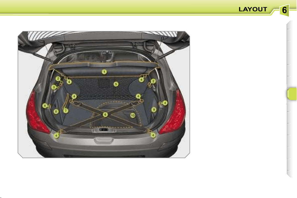
93
BOOT LAYOUT
1. Rear shelf or shelf with
integrated storage compartment
(see details on following page)
2. Hooks
(see details on following page)
3. 12 V accessories socket
(see details on following page)
4. Stowing rings
5. Luggage retaining net
(see details on following page)
6. Movable straps
(see details on following page)
7. Luggage retaining strap
8. Enclosed storage tray
9. Open storage tray
10. Storage box
(see details on following page)
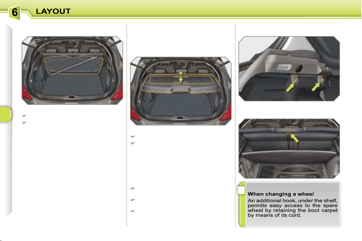
i
94
To remove the shelf:
unhook the two cords,
raise the shelf slightly, then remove it.
There are several options for storing the
shelf:
- either upright behind the front seats,
- or upright behind the rear seats using
one of the movable straps.
Rear shelf
To remove the shelf:
unhook the two cords,
raise the shelf slightly, then remove it.
There are several options for storing the
shelf:
- either upright behind the front seats,
- or upright behind the rear seats using
one of the movable straps.
To open the cover, from inside or out-
side, raise one of the two handles.
To close the cover, first raise the
handle.
To remove the cover, raise both hand-
les at the same time.
Shelf with integrated storage compartment
The hooks permit the securing of shop-
ping bags.
Hooks
This permits the storage of any object so
that it cannot be seen from the outside
and without hindering rearward visibility.
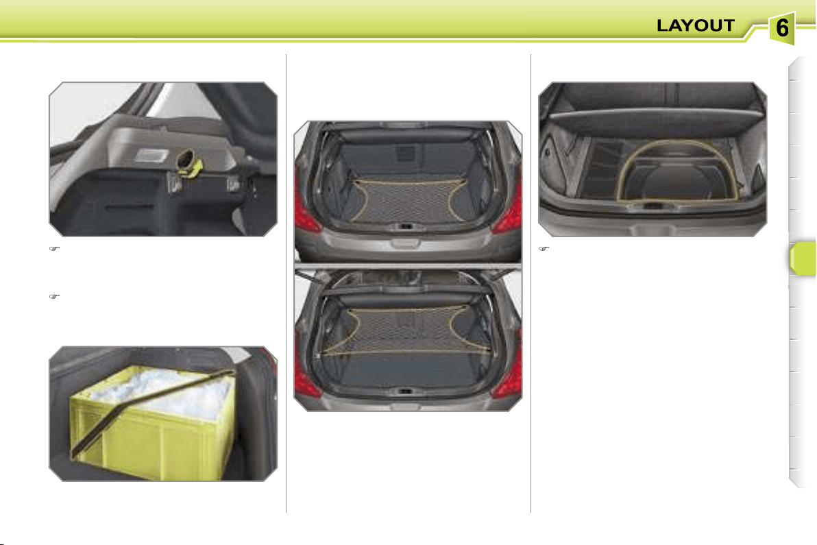
95
Hooked onto the stowing rings, this en-
ables you to secure your luggage.
Luggage retaining net
Raise the boot carpet to gain access
to the storage box.
This has areas for storing a box of spare
bulbs, a first aid kit, a puncture repair
kit, two warning triangles, ...
Storage box
In order to connect a 12 V accesso-
ry (max power: 100 Watts), remove
the cap and connect the appropriate
adaptor.
Turn the key to the ignition position.
12 V accessories socket
There are three possible positions:
- flat at the bottom of the boot,
- horizontal at the rear shelf,
- vertical at the back of the rear seats.
Movable straps
Hooked onto the stowing rings, they
permit securing of your luggage.
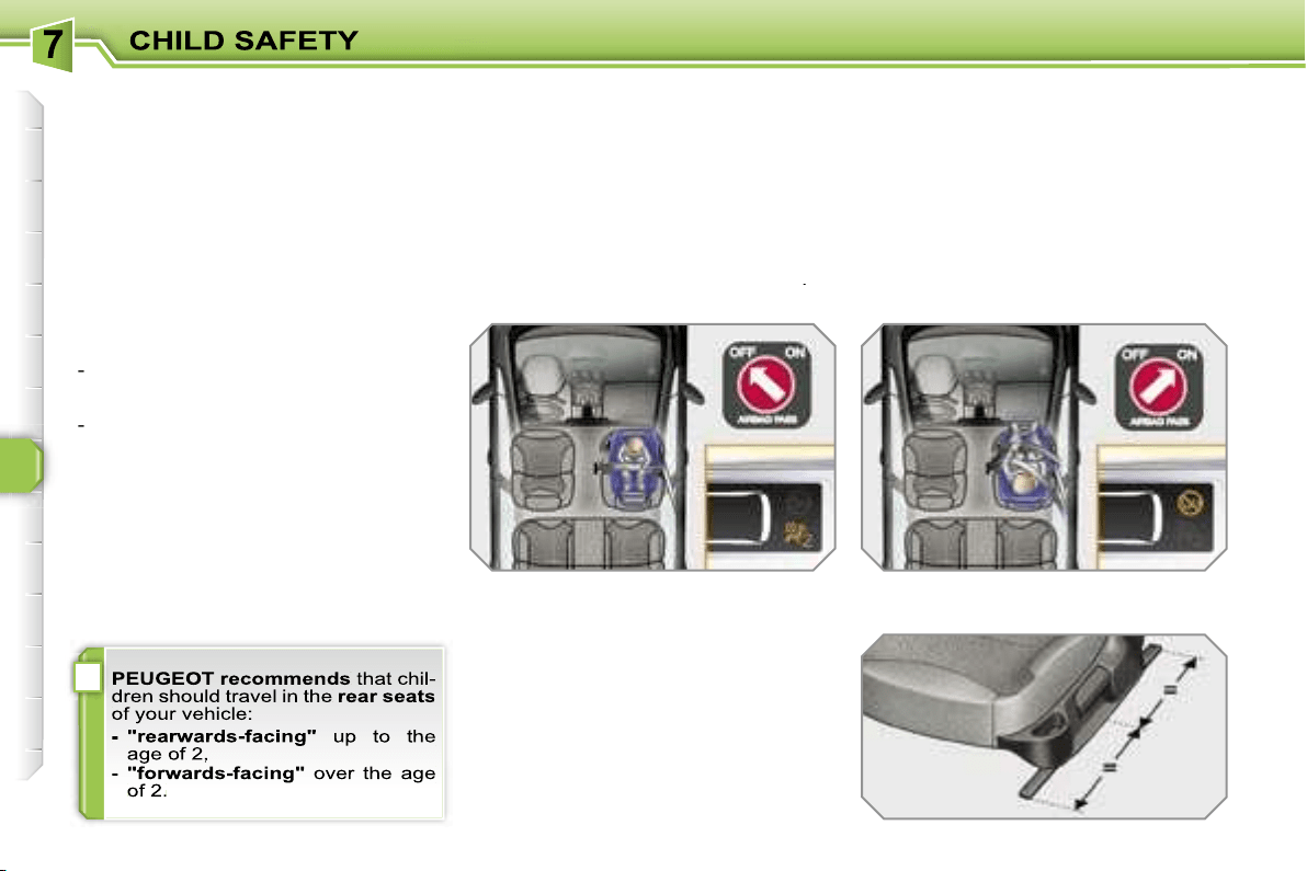
i
96
GENERAL POINTS RELATING
TO CHILD SEATS
Although one of PEUGEOT’s main cri-
teria when designing your vehicle, the
safety of your children also depends on
you.
For maximum safety, please follow
these precautions:
- in accordance with Directive 2003/20,
all children under the age of 12 or
less than one metre fifty tall must
travel in approved child seats suited
to their weight
, on seats fitted with a
seat belt or ISOFIX mountings*.
-
statistically, the safest seats in
your vehicle for the transportation
of children are the rear seats,
-
a child weighing less than 9 kg must
travel in the "rearwards-facing" position
both in the front and in the rear.
INSTALLING A CHILD SEAT
USING A THREE POINT SEAT
BELT
"Forwards-facing"
When a "forwards-facing" child seat is
installed on the
front passenger seat
,
adjust the vehicle’s seat to the interme-
diate longitudinal position with the seat
back upright and leave the passenger
air bag armed.
"Rearwards-facing"
When a "rearwards-facing" child seat is
installed on the
front passenger seat
,
it is essential that the passenger air
bag is disarmed. Otherwise,
the child
would risk being seriously injured or
killed if the air bag were to inflate
.
Intermediate longitudinal
position
* The rules for transporting children are
specific to each country. Consult the
current legislation in your country.
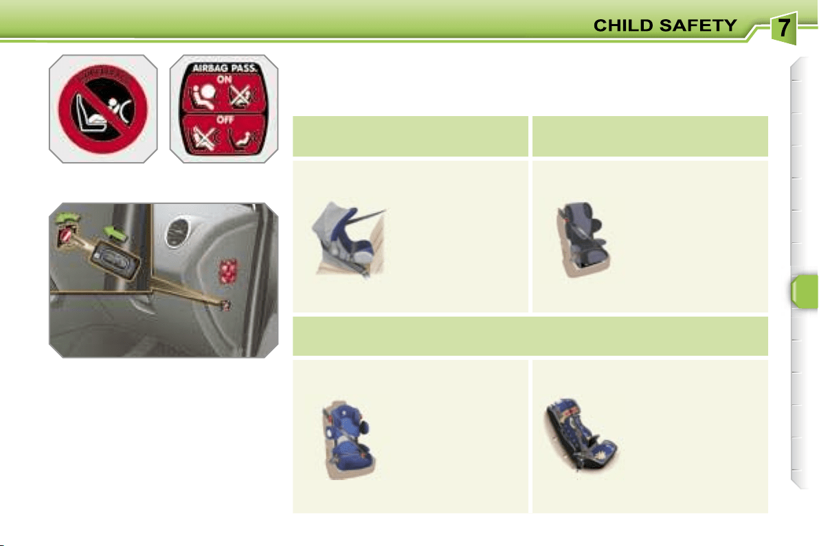
97
Passenger air bag OFF
CHILD SEATS RECOMMENDED BY PEUGEOT
PEUGEOT offers a complete range of recommended child seats which are secu-
red using a
three point seat belt
:
Group 0: from birth to 10 kg
Group 0+: from birth to 13 kg
Groups 1, 2 and 3: from 9 to 36 kg
L1
"ROMER
Baby-Safe Plus"
Installed in the
rear-facing position.
L2
"KIDDY Life"
For the safety
of young children
(from 9 to 18 kg),
PEUGEOT
recommends use
of the restraining
cushion.
Groups 2 and 3: from 15 to 36 kg
L3
"RECARO Start".
L4
"KLIPPAN Optima"
From the age
of 6 years
(approximately 22 kg),
the booster is used
on its own.
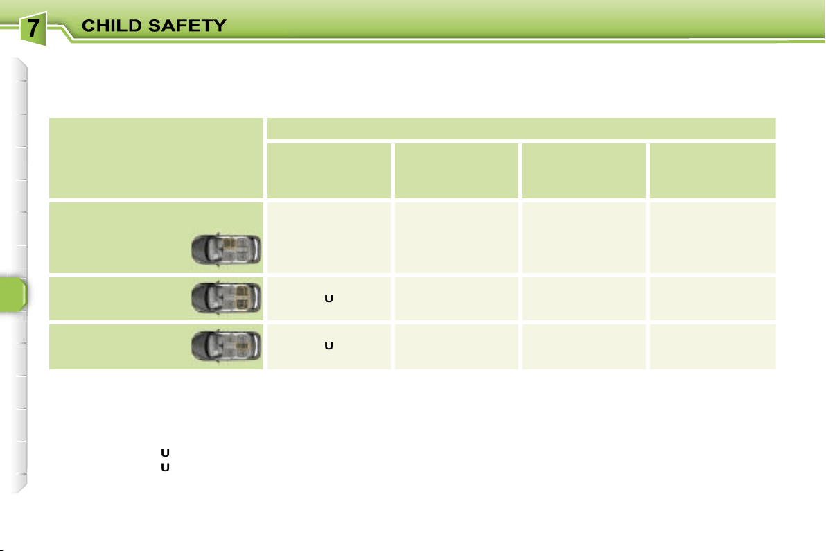
98
LOCATION OF CHILD SEATS SECURED USING THE SEAT BELT
In accordance with European regulations (Directive 2005/40), this table indicates the options for installing child seats secured
using the seat belt and universally approved (a) in relation to the weight of the child and the seat in the vehicle.
(a) Universal child seat: child seat which can be installed in all vehicles using the seat belt.
(b) Group 0: from birth to 10 kg.
(c) Consult the legislation in force in your country before installing your child on this seat.
U:
seat suitable for the installation of a child seat secured using the seat belt and univerally approved "rear facing" and/or
"forward facing".
U (R1):
identical to
U
, with the vehicle’s seat adjusted to the intermediate longitudinal position.
U (R2):
identical to
U
, with the vehicle’s seat adjusted to the highest position.
L-:
only the child seats indicated can be installed on the seat concerned (according to country).
* The seat’s head restraint must be removed and stored.
Seat
Weight of the child/
indicative age
Less than 13 kg
(groups 0 (b)
and 0+)
Up to ≈ 1 year
From 9 to 18 kg
(group 1)
From 1 to ≈ 3 years
From 15 to 25 kg
(group 2)
From 3 to ≈ 6 years
From 22 to 36 kg
(group 3)
From 6 to ≈ 10 years
Front passenger seat (c)
- fixed
- height adjustable
U (R1)
U (R2)
U (R1)
U (R2)
U (R1)
U (R2)
U (R1)
U (R2)
Rear side seats
U
U*
U*
U*
Rear centre seat
U
U*
(except L2)
U*
L3
U*
L3
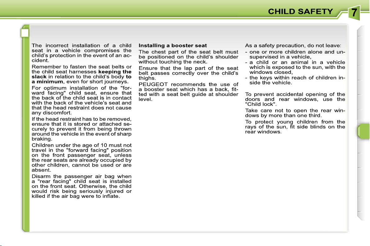
!
99
ADVICE ON CHILD SEATS
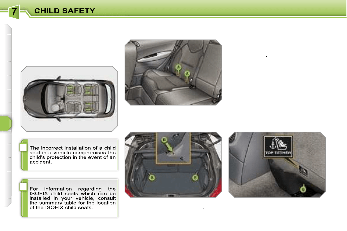
!
i
100
"ISOFIX" MOUNTINGS
Your vehicle has been approved in accord-
ance with the
new ISOFIX regulation
.
The seats, represented below, are fitted
with regulation ISOFIX mountings:
The Isofix mountings are three rings for
each seat:
- two rings
A
, located between the ve-
hicle seat back and cushion, indicated
by a label,
- a ring
B
, for fixing the upper strap re-
ferred to as the
TOP TETHER
.
This ISOFIX mounting system guaran-
tees you fast, reliable and safe fitting of
the child seat in your vehicle.
The
ISOFIX child seats
are fitted with
two locks which are secured easily on
the two rings
A
.
Some also have an
upper strap
which
is attached to ring
B
.
To attach this strap, raise the vehicle
seat’s head restraint then pass the hook
between its rods. Then fix the hook on
ring
B
and tighten the upper strap.
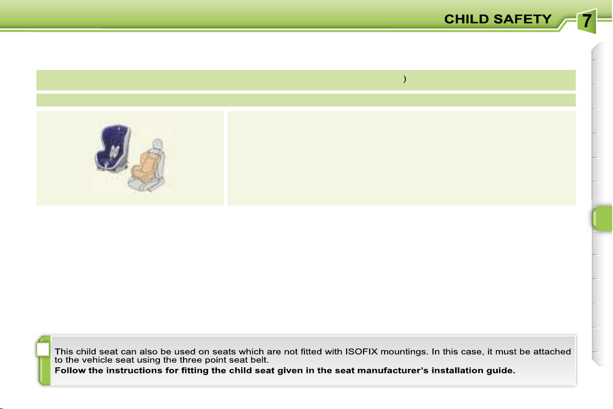
i
101
ISOFIX CHILD SEAT RECOMMENDED BY PEUGEOT AND APPROVED FOR YOUR VEHICLE
ISOFIX RÖMER Duo Plus
(size category
B1
)
Group 1: from 9 to 18 kg
Installed in the forward facing position.
Fitted with an upper strap to be secured on the ISOFIX upper ring,
referred to as the TOP TETHER.
Three seat body angles: sitting, reclining, lying.
102
SUMMARY TABLE FOR THE LOCATION OF ISOFIX CHILD SEATS
In accordance with European Regulations (ECE 16), this table indicates the options for installing ISOFIX child seats on seats
in the vehicle fitted with ISOFIX mountings.
In the case of universal and semi-universal ISOFIX child seats, the ISOFIX size category, determined by a letter from
A
to
G
,
is indicated on the child seat next to the ISOFIX logo.
IUF:
seat suitable for the installation of an
I
sofix
U
niversal seat, "
Forward
facing" secured using the "Top Tether" upper strap.
IL-SU:
seat suitable for the installation of an
I
sofix
S
emi-
U
niversal seat either:
- "rear facing" fitted with a "Top Tether" upper strap or a support,
- "forward facing" fitted with a support,
- an infant car seat fitted with a "Top Tether" upper strap or a support.
For advice on securing of the "Top Tether" upper strap, refer to the "Isofix mountings section".
X:
seat not suitable for the installation of an ISOFIX seat of the size category indicated.
* The ISOFIX infant car seat, secured on the lower rings of a vehicle ISOFIX seat, occupies two rear seats.
Weight of the child/
indicative age
Less than 10 kg
(group 0)
Up to approx.
6 months
Less than 10 kg
(group 0)
Less than 13 kg
(group 0+)
Up to approx. 1 year
From 9 to 18 kg
(group 0)
From approx. 1 to 3 years
Type of ISOFIX
child seat
Infant car seat
"rear facing"
"rear facing"
"forward facing"
ISOFIX size category
F
G
C
D
E
C
D
A
B
B1
ISOFIX child seats
universal and semi-universal
which can
be installed on the:
- front passenger seat
X
IL-SU
IL-SU
IUF
- rear side seats
IL-SU*
IL-SU
IL-SU
IUF
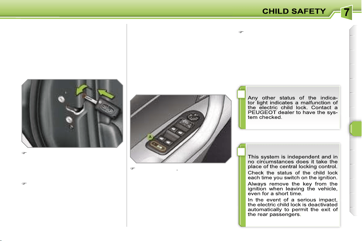
!
!
103
MANUAL CHILD LOCK
Mechanical system to prevent opening
of the rear door using its interior control.
The control is located on the edge of
each rear door.
Turn the red control one quarter of
a turn to the right using the ignition
key.
ELECTRIC CHILD LOCK
Remote control system to prevent open-
ing of the rear doors using their interior
controls and use of the rear electric win-
dows.
The control is located on the driver’s
door, with the electric window controls.
Press button
A
.
The indicator light on button
A
comes
on, accompanied by a message on the
multifunction display.
This indicator light remains on until the
child lock is deactivated.
Locking
Unlocking
Turn the red control one quarter of a
turn to the left using the ignition key.
Activation
Deactivation
Press button
A
again.
The indicator light on button
A
switches
off, accompanied by a message on the
multifunction display.
This indicator light remains off until the
child lock is activated.
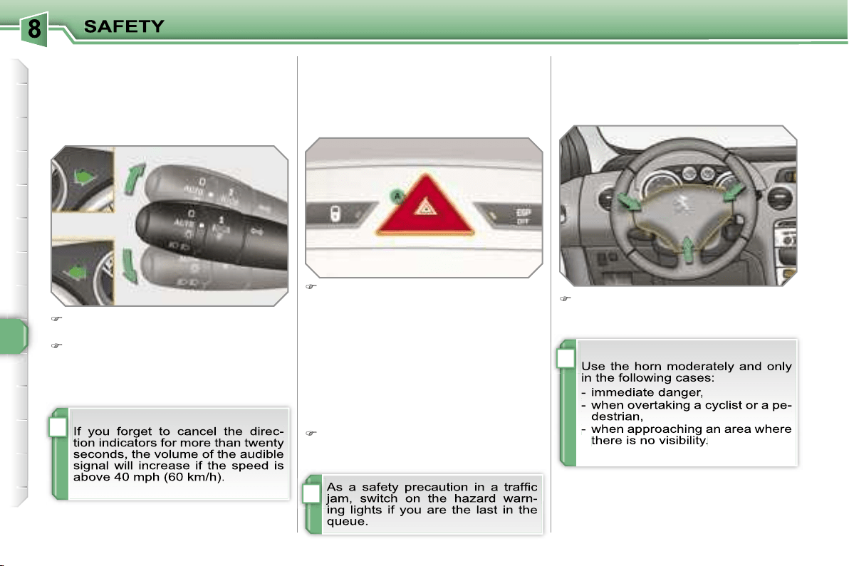
i
i
i
104
DIRECTION INDICATORS
Selection of the left or right direction in-
dicators to signal a change of direction
of the vehicle.
Lower the lights stalk fully when mo-
ving to the left.
Raise the lights stalk fully when mov-
ing to the right.
HAZARD WARNING LIGHTS
A visual warning by means of the direc-
tion indicators to alert other road users
to a vehicle breakdown, towing or ac-
cident.
Press button
A
, the direction indica-
tors flash.
They can operate with the ignition off.
Automatic lighting of hazard
warning lights
When braking in an emergency, de-
pending on the deceleration, the hazard
warning lights come on.
They will switch off automatically the
first time you accelerate.
If they do not, press button
A
to
switch the direction indicators off.
HORN
Audible warning to alert other road us-
ers to an imminent danger.
Press one of the spokes of the stee-
ring wheel.
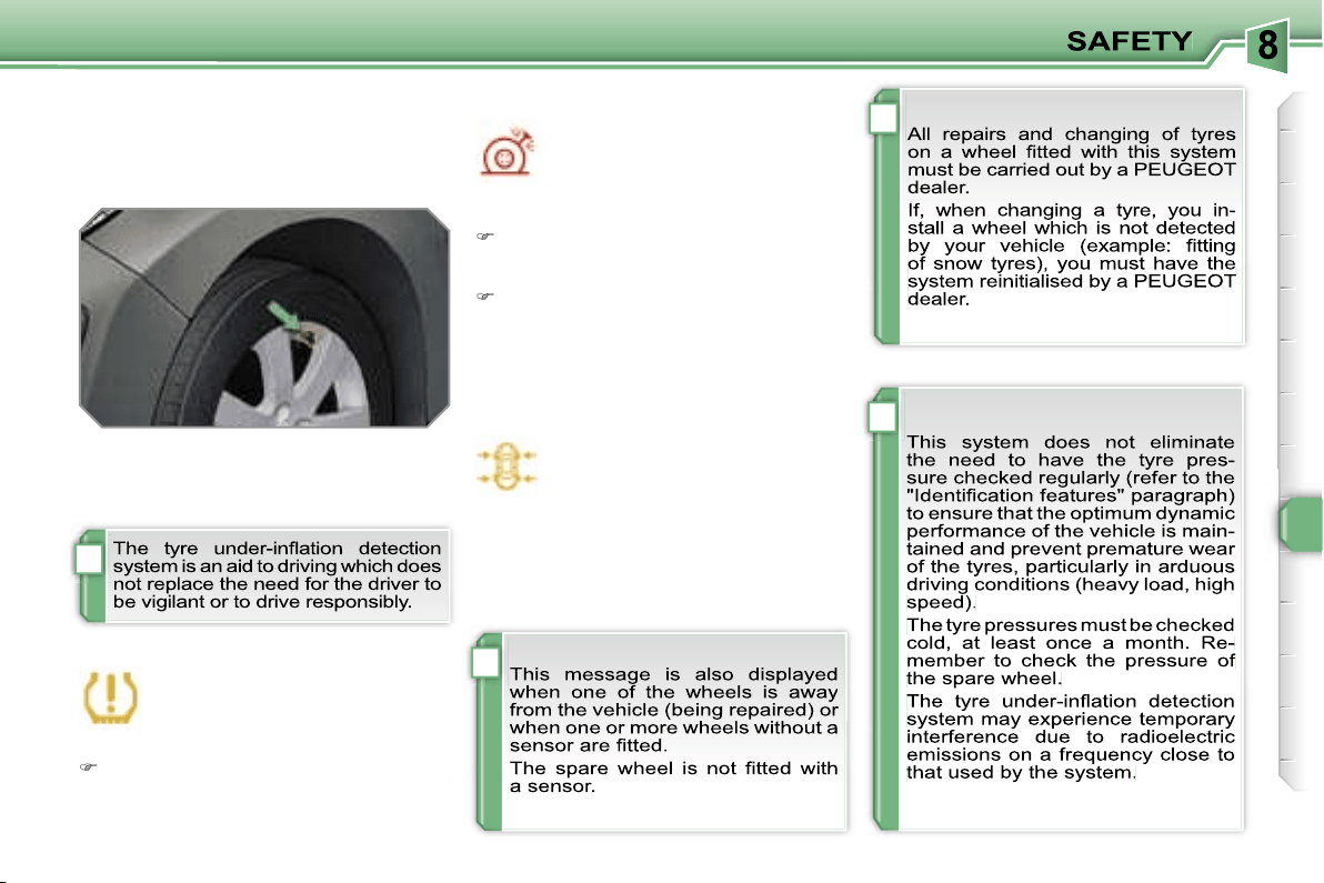
!
i
i
i
105
TYRE UNDER-INFLATION
DETECTION
System which automatically checks the
pressure of the tyres while driving.
Sensors fitted in each valve trigger a
warning in the event of malfunction
(speed above 12 mph (20 km/h)).
This warning light is displayed on
the instrument panel and/or a mes-
sage appears on the multifunction
display, accompanied by an audi-
ble signal, to locate the wheel concerned.
Check the tyre pressures as soon as possible.
This check must be carried out when
the tyres are cold.
Flat tyre
The
STOP
warning light comes on
and/or this warning light is displayed
on the instrument panel, accom-
panied by an audible signal and a
message on the multifunction dis-
play locating the wheel concerned.
Stop immediately, avoiding any sud-
den movement of the steering wheel
and the brakes.
Change the damaged wheel (punc-
tured or very deflated tyre), and have
the tyre pressure checked as soon
as possible.
Puncture
Sensor(s) not detected or faulty
This warning light is displayed
on the instrument panel and/or
a message appears on the mul-
tifunction display, accompanied
by an audible signal, to locate the wheel
or wheels which are not detected or to
indicate a fault in the system.
Contact a PEUGEOT dealer to replace
the faulty sensor(s).
!
i
106
BRAKING ASSISTANCE
SYSTEMS
Group of supplementary systems which
help you to obtain optimum braking in
complete safety in emergency situa-
tions:
- the anti-lock braking system (ABS),
- the electronic brake force distribution
(EBFD),
- the emergency braking assistance
(EBA).
Anti-lock braking system
and electronic brake force
distribution
Linked systems which improve the sta-
bility and manoeuvrability of your vehi-
cle when braking, in particular on poor
or slippery surfaces.
Operating fault
If this warning light comes on,
accompanied by an audible sig-
nal and a message on the mul-
tifunction display, it indicates a
malfunction of the anti-lock braking sys-
tem which could result in loss of control
of the vehicle when braking.
If this warning light comes on,
together with the
STOP
and
ABS warning lights, accompa-
nied by an audible signal and a
message on the multifunction display, it
indicates a malfunction of the electron-
ic brake force distribution which could
result in loss of control of the vehicle
when braking.
You MUST stop as soon as it is safe
to do so.
In both cases, contact a PEUGEOT
dealer.
Emergency braking assistance
System which, in an emergency, ena-
bles you to obtain the optimum braking
pressure more quickly, thus reducing
the stopping distance.
Activation
The anti-lock braking system comes
into operation automatically when there
is a risk of wheel lock.
Normal operation of the ABS may make
itself felt by slight vibration of the brake
pedal.
Activation
It is triggered by the speed at which the
brake pedal is pressed.
The effect of this is a reduction in the
resistance of the pedal and an increase
in braking efficiency.
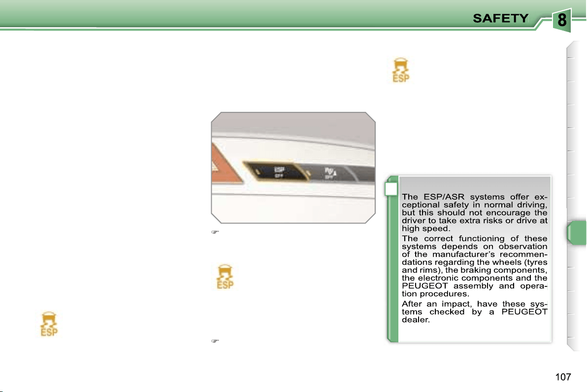
!
Disarming
In exceptional conditions (starting a
vehicle which is bogged down, stuck
in snow, on soft ground, ...), it may be
advisable to disarm the ASR and ESP
systems, so that the wheels can move
freely and regain grip.
Press the
"ESP OFF"
button, loca-
ted in the centre of the fascia.
If this warning light comes on on the in-
strument panel and the indicator light on
the button comes on, this indicates that
the ASR and ESP systems are disarmed.
Reactivation
These systems are reactivated automat-
ically each time the ignition is switched
back on or from 30 mph (50 km/h).
Press the
"ESP OFF"
button again
to reactivate them manually.
Operating fault
If this warning light comes on,
accompanied by an audible sig-
nal and a message on the mul-
tifunction display, this indicates
a malfunction of these systems.
Contact a PEUGEOT dealer to have the
systems checked.
TRAJECTORY CONTROL
SYSTEMS
Associated systems which guarantee
the directional stability of the vehicle
within the limits of the laws of physics:
- the anti-skid regulation (ASR),
- the electronic stability programme
(ESP).
Activation
These systems are activated automati-
cally each time the vehicle is started.
Anti-skid regulation and
electronic stability programme
The anti-skid regulation optimises trac-
tion to prevent skidding of the wheels,
by acting on the brakes of the driving
wheels and on the engine.
The electronic stability programme acts
on the brake of one or more wheels and
on the engine to keep the vehicle on the
trajectory required by the driver.
They come into operation in the event
of a grip or trajectory problem.
This is indicated by flashing of
this warning light on the instru-
ment panel.
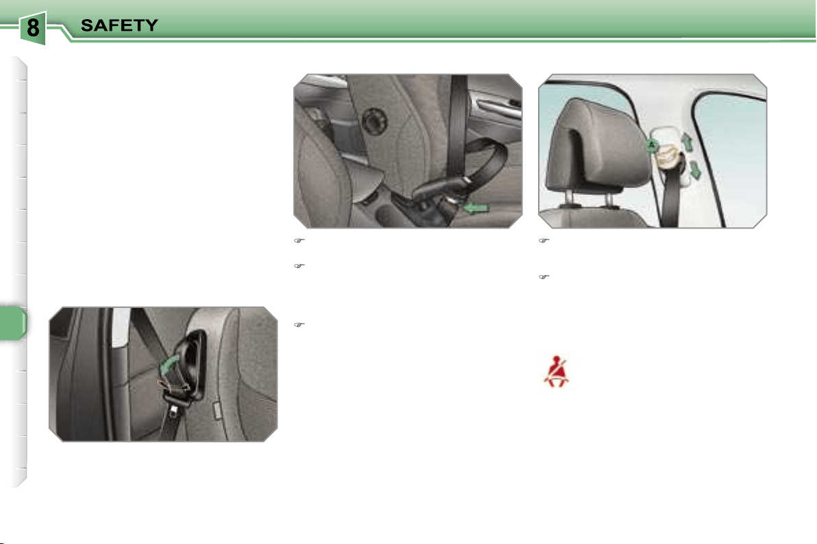
108
Height adjustment
Seat belt not fastened/unfastened
warning light
Fastening
Pull the strap, then insert the tongue
in the buckle.
Check that the seat belt is fastened
correctly by pulling the strap.
To lower the attachment point,
squeeze the control
A
and slide it
downwards.
To raise the attachment point, slide
the control
A
upwards.
When the ignition is switched
on, this warning light comes on,
either on the instrument panel
or on the seat belt and passen-
ger’s front air bag warning lights
display, if the driver and/or the front pas-
senger has not fastened his seat belt.
From approximately 12 mph (20 km/h) this
warning light flashes for two minutes ac-
companied by an audible signal of increas-
ing volume. Once these two minutes have
elapsed, this warning light remains on until
the driver and/or the front passenger fas-
tens his seat belt.
Unfastening
Press the red button on the buckle.
SEAT BELTS
Front seat belts
The front seat belts are fitted with a pre-
tensioning and force limiting system.
This system improves safety in the front
seats in the event of a front impact. De-
pending on the severity of the impact,
the pretensioning system instantly tight-
ens the seat belts against the body of
the occupants.
The pretensioning seat belts are active
when the ignition is on.
The force limiter reduces the pressure
of the seat belt on the chest of the occu-
pant, so increasing his protection.
On the 3-door versions, lower the sup-
port incorporated in the control to rest
the seat belt on it. This enables you to
retrieve the seat belt more easily when
you have to put it back on.
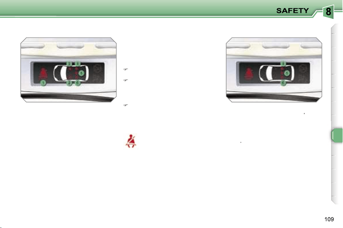
1.
Front and/or rear seat belts not
fastened/unfastened warning light.
2.
Front left seat belt warning light.
3.
Front right seat belt warning light.
4.
Rear right seat belt warning light.
5.
Rear centre seat belt warning light.
6.
Rear left seat belt warning light.
The corresponding warning light
2
or
3
comes on in red on the seat belt and
passenger’s front air bag warning lights
display if the seat belt is not fastened or
is unfastened.
Seat belt not fastened/unfastened
warning lights display
Rear seat belts
The rear seats are each fitted with a
three-point inertia reel seat belt with
force limiter (with the exception of the
rear centre seat).
Seat belt unfastened warning light
This warning light comes on,
either on the instrument panel
or on the seat belt and passen-
ger’s front air bag warning lights
display, when one or more rear passen-
gers unfasten their seat belt.
From approximately 12 mph (20 km/h),
this warning light flashes for two minutes
accompanied by an audible signal of in-
creasing volume. Once these two minutes
have elapsed, this warning light remains
on until the one or more rear passengers
fasten their seat belt.
Fastening
Pull the strap, then insert the tongue
in the buckle.
Check that the seat belt is fastened
correctly by pulling the strap.
Seat belt unfastened warning lights
display
When the ignition is switched on, the
corresponding warning lights
4
,
5
and
6
come on in red for approximately
30 seconds, if the seat belt is not fas-
tened.
When the engine is running or the vehi-
cle is moving, the corresponding warning
light
4
,
5
or
6
comes on in red, accompa-
nied by an audible signal and a message
on the multifunction display, if a rear pas-
senger has unfastened his seat belt.
Unfastening
Press the red button on the buckle.
i
110
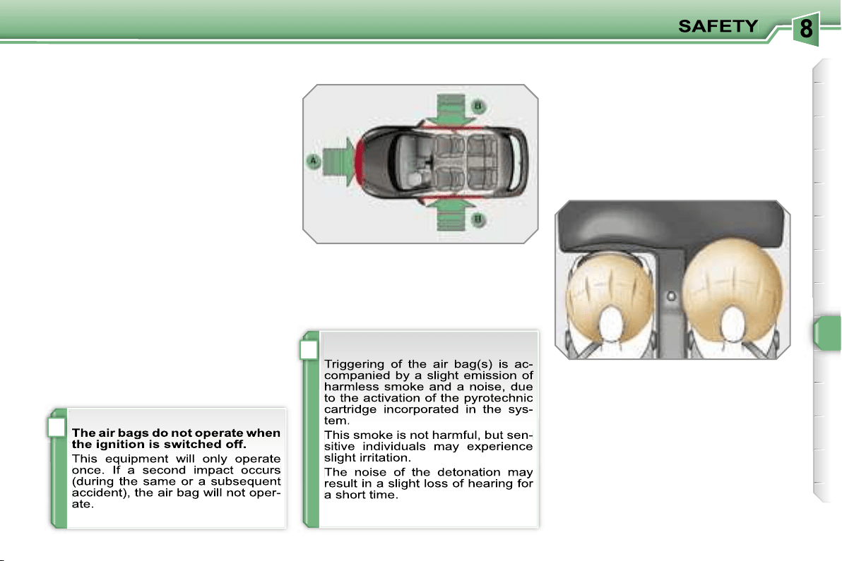
i
!
111
AIR BAGS
System designed to maximise the safety
of the occupants (with the exception of
the rear centre passenger) in the event
of violent collisions. It supplements the
action of the force-limiting seat belts
(with the exception of the rear centre
passenger).
If a collision occurs, the electronic de-
tectors record and analyse the front and
side impacts sustained in the impact
detection zones:
- in the case of a serious impact, the air
bags are triggered instantly and pro-
tect the occupants of the vehicle (with
the exception of the rear centre pas-
senger); immediately after the impact,
the air bags deflate rapidly so that
they do not hinder visibility or the exit
of the occupants,
- in the case of a minor or rear impact
or in certain roll-over conditions, the
air bags will not be triggered; the seat
belt alone is sufficient to provide opti-
mum protection in these situations.
Front air bags
System which protects the driver and
front passenger in the event of a seri-
ous front impact in order to limit the risk
of injury to the head and chest.
The driver’s air bag is incorporated in
the centre of the steering wheel; the
front passenger’s air bag is incorporat-
ed in the fascia above the glove box.
Activation
The air bags are triggered simultane-
ously, unless the passenger’s front air
bag is disarmed, in the event of a seri-
ous front impact applied to all or part of
the front impact zone
A
, in the longitu-
dinal centreline of the vehicle on a hori-
zontal plane and directed from the front
to the rear of the vehicle.
The front air bag inflates between the
front occupant of the vehicle and the
fascia to cushion his forward move-
ment.
Impact detection zones
A.
Front impact zone.
B.
Side impact zone.
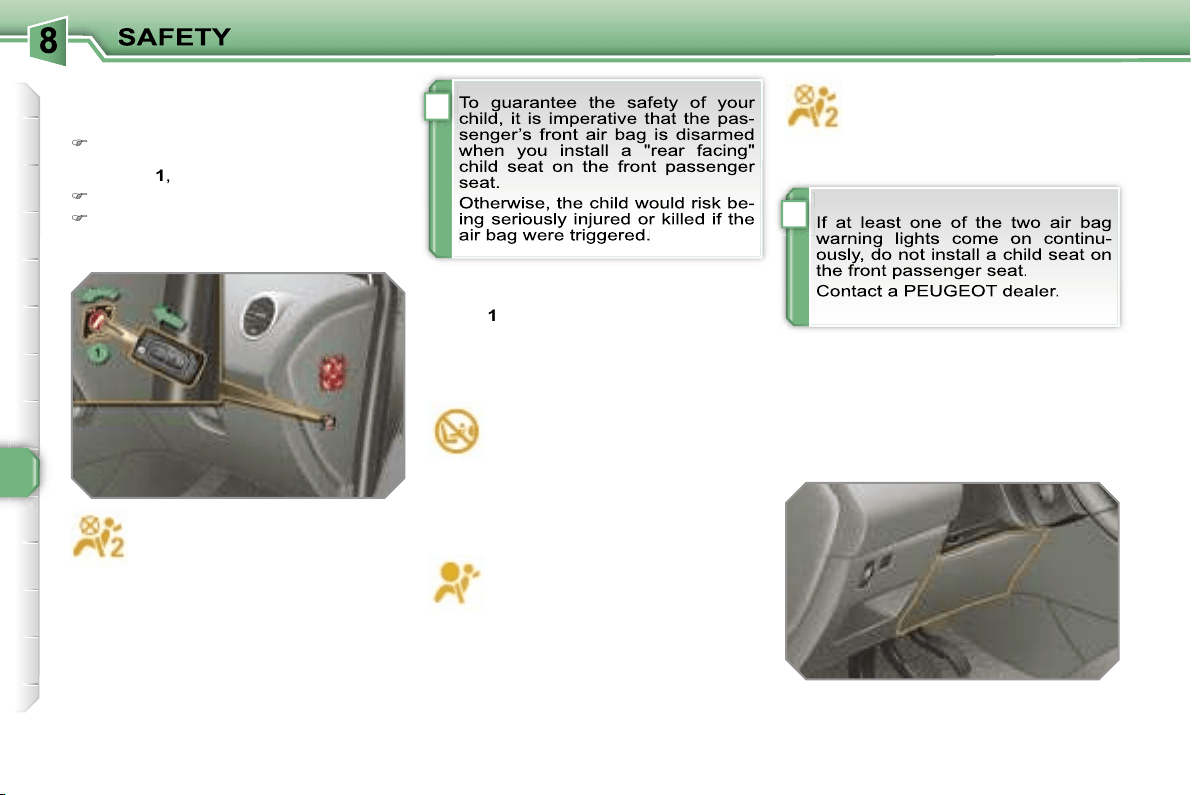
!
!
112
Operating fault
If this warning light comes on on
the instrument panel, accompa-
nied by an audible warning and
a message on the multifunction
display, contact a PEUGEOT dealer to
have the system checked. The air bags
may no longer be triggered in the event
of a serious impact.
Steering column air bag*
System which protects the driver’s
knees in the event of a serious front im-
pact.
This air bag is incorporated in the fascia
below the steering column.
Activation
It is deployed at the same time as the
front air bags.
Reactivation
When you remove the child seat, turn
switch
1
to the
"ON"
position to re-arm
the air bag and so guarantee the safety
of your front passenger in the event of
an impact.
With the ignition on, this warn-
ing light comes on on the seat
belt and passenger’s front air
bag warning lights display for
approximately one minute, if the pas-
senger’s front air bag is activated.
According to version, this warn-
ing light comes on either on
the instrument panel or on the
seat belt and passenger’s front
air bag warning lights display when the
ignition is on and until the air bag is re-
armed.
If this warning light flashes,
contact a PEUGEOT dealer.
The passenger’s front air bag
may no longer be triggered in
the event of a serious impact.
Deactivation
Only the passenger’s front air bag can
be disarmed:
with the ignition off,
insert the key
in the passenger air bag disarming
switch
1
,
turn it to the
"OFF"
position,
then, remove the key keeping the
switch in this position.
* According to country.
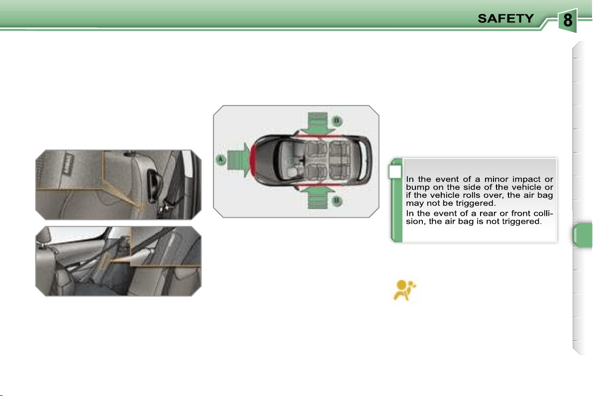
!
113
Side air bags
System which protects the driver and
passengers (with the exception of the
rear centre passenger) in the event of a
serious side impact in order to limit the
risk of injury to the chest.
Each side air bag is incorporated:
- in the front, in the seat back frame, on
the door side,
- in the rear, in the side trim (except on
3-door models).
Activation
The side air bags are triggered unilater-
ally in the event of a serious side impact
applied to all or part of the side impact
zone
B
, perpendicular to the longitudi-
nal centreline of the vehicle on a hori-
zontal plane and directed from the out-
side towards the inside of the vehicle.
Curtain air bags
System which protects the driver and
passengers (with the exception of the
rear centre passenger) in the event of a
serious side impact in order to limit the
risk of injury to the head.
Each curtain air bag is incorporated in
the pillars and the upper section of the
passenger compartment.
Operating fault
Activation
The curtain air bag is triggered at the
same time as the corresponding side air
bags in the event of a serious side impact
applied to all or part of the side impact
zone
B
, perpendicular to the longitudinal
centreline of the vehicle on a horizontal
plane and directed from the outside to-
wards the inside of the vehicle.
The curtain air bag inflates between the
front or rear occupant of the vehicle and
the windows.
Impact detection zones
A.
Front impact zone.
B.
Side impact zone.
If this warning light comes on on
the instrument panel, accompa-
nied by an audible signal and a
message on the multifunction
display, contact a PEUGEOT dealer to
have the system checked. The air bags
may no longer be triggered in the event
of a serious impact.
The side air bag inflates between the
front or rear occupant of the vehicle and
the corresponding door trim pad.
!
114
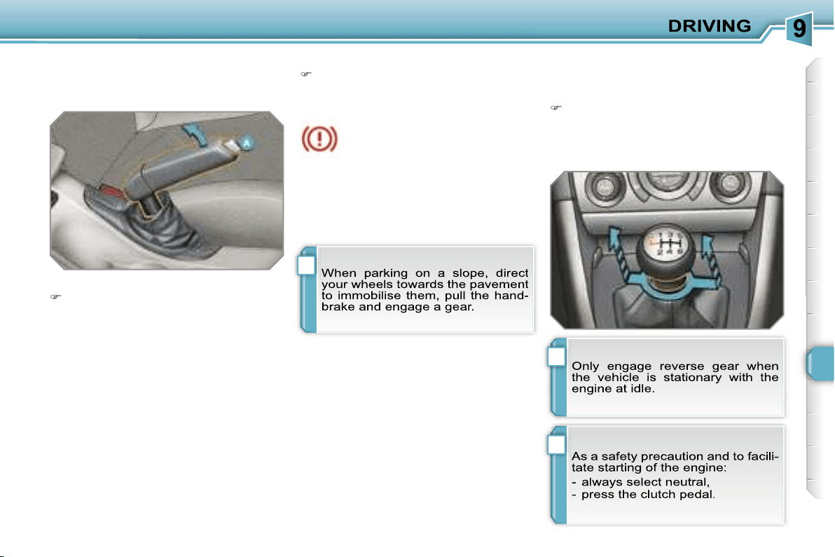
!
i
!
115
HANDBRAKE
Mechanical brake to hold the vehicle
when stationary.
Applying
Pull the handbrake to immobilise
your vehicle.
When the vehicle is being driv-
en, if this warning light and the
STOP
warning light come on,
accompanied by an audible
signal and a message on the multi-
function display, this indicates that the
handbrake is still on or has not been
properly released.
Releasing
Pull on the handle and press the but-
ton
A
to release the handbrake.
6-SPEED MANUAL GEARBOX
Engaging reverse gear
Raise the ring under the knob and
push the gear lever to the left then
forwards.
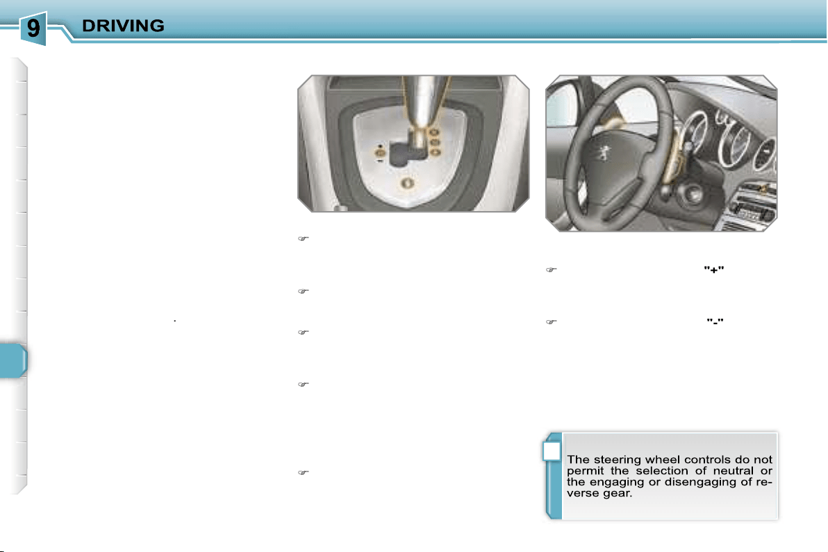
i
116
6-SPEED PILOTED MANUAL
GEARBOX
Six-speed piloted manual gearbox
which offers a choice between the com-
fort of fully automatic operation or the
pleasure of manual gear changing.
Therefore, three driving modes are of-
fered:
- the
automatic
mode for automatic
control of the gears by the gearbox,
- the
sequential
mode for manual
changing of the gears by the driver,
- the
auto sequential
mode to over-
take, for example, remaining in auto-
matic mode while using the functions
of the sequential mode.
A
Sport
function is available in auto-
matic or sequential mode for a more dy-
namic style of driving.
The use of this gearbox enables you to
benefit from an additional function: the
hill start assistance
.
Gear lever
R.
Reverse
With your foot on the brake, move
the lever upwards to select this posi-
tion.
N.
Neutral.
With your foot on the brake, select
this position to start.
A.
Automatic mode.
Move the lever downwards to select
this mode.
M. +/-
Sequential mode with manual
changing of the gears.
Move the lever downwards then to
the left to select this mode, then:
- push the lever forwards to change
up a gear,
- or pull the lever rearwards to
change down a gear.
S.
Sport function.
Press this button to activate or deac-
tivate this
function.
Steering wheel controls
+.
Change up control to the right of the
steering wheel.
Press the back of the
"+"
steering
wheel control to change up a gear.
-.
Change down control to the left of
the steering wheel.
Press the back of the
"-"
steering
wheel control to change down a
gear.
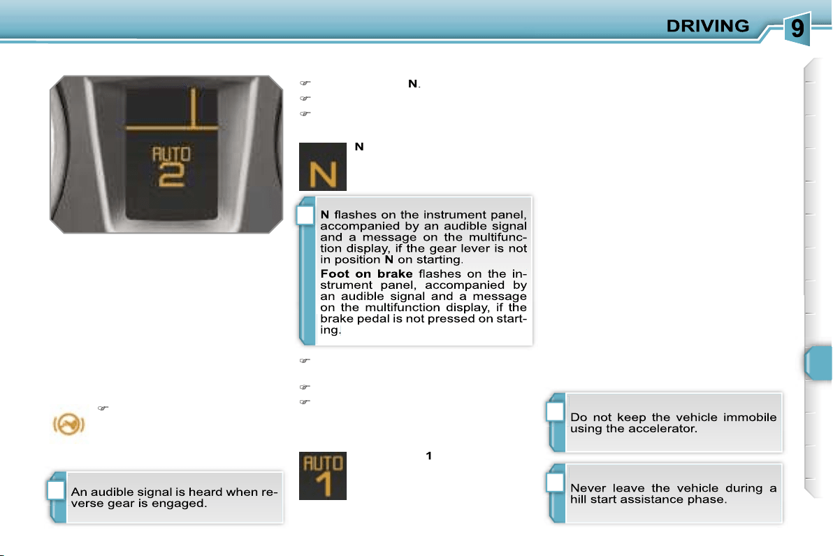
i
i
!
i
117
Displays on the instrument panel
Gear lever positions
Moving off
N.
Neutral
R.
Reverse
1, 2, 3, 4, 5, 6.
Gears in sequential
mode
AUTO.
This comes on when the
automatic mode is selected.
It switches off on changing to
sequential mode.
S.
Sport (Sport function)
Place your
foot on the
brake
when this warning
light flashes (e.g.: when
starting the engine).
Select position
N
.
Press the brake pedal down fully.
Start the engine.
Select first gear (position
M
or
A
) or
reverse (position
R
).
Release the handbrake.
Take your foot off the brake pedal,
then accelerate.
AUTO
and
1
or
R
appear on
the instrument panel display.
Hill start assistance
This is an additional function associated
with this gearbox. It permits the tempo-
rary immobilisation of your vehicle.
It maintains the pressure of the brakes
briefly, long enough for you to move
your foot from the brake pedal to the
accelerator pedal.
It coms into operation if the vehicle is
immobilised by pressing the brake ped-
al and in accordance with the gradient:
- on an ascending gradient, with the ve-
hicle stationary, gear lever in position
A
or
M
, the vehicle is kept immobile
briefly when the brake pedal is re-
leased,
- on a descending gradient, with the ve-
hicle stationary, gear lever in position
R
, the vehicle is kept immobile briefly
when the brake pedal is released.
N
appears on the instrument
panel display.
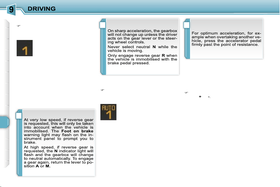
i
! i
118
Sequential mode
When the vehicle has moved off, se-
lect position
M
to change to sequen-
tial mode.
AUTO
disappears and the
gears engaged appear in suc-
cession on the instrument
panel display.
The gear change requests are only car-
ried out if the engine speed permits.
It is not necessary to release the accel-
erator during gear changes.
When braking or slowing down, the
gearbox changes down automatically to
permit reacceleration of the vehicle in
the correct gear.
The gearbox is then operating in auto-
active mode, without any action on the
part of the driver. It continuously selects
the most suitable gear in relation to the
following parameters:
- style of driving,
- profile of the road.
AUTO
and the gear engaged
appear on the instrument pan-
el display.
Automatic mode
Following use of the sequential
mode, select position
A
to return to
the automatic mode.
"Auto sequential mode"
This mode enables you to overtake, for
example, remaining in automatic mode
while using the functions of the sequen-
tial mode.
Activate steering wheel control posi-
tion
+
or
-
.
The gearbox engages the gear request-
ed if the engine speed permits.
AUTO
is
still displayed on the instrument panel.
After a few moments without any action
on the controls, the gearbox resumes
automatic control of the gears.
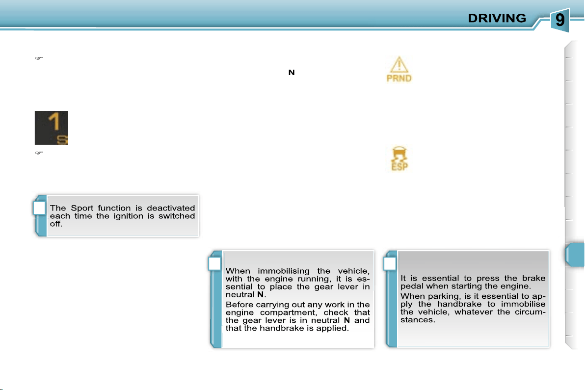
!!
i
119
Stopping the vehicle
Before switching off the engine, you can
choose to:
- move to position
N
to engage neutral,
- leave the gear engaged; in this case,
it will not be possible to move the ve-
hicle.
In both cases, it is essential that you
apply the handbrake to immobilise the
vehicle.
Operating fault
With the ignition on, if this warn-
ing light comes on and
AUTO
flashes, accompanied by an au-
dible signal and a message on
the multifunction display, this indicates
a malfunction of the gearbox.
Contact a PEUGEOT dealer without de-
lay.
With the ignition on, if the warn-
ing light above and this warning
light come on, accompanied by
an audible signal and a mes-
sage on the multifunction display, this
indicates a malfunction of the hill start
assistance.
Contact a PEUGEOT dealer without de-
lay.
Sport function
Following selection of the sequential
mode or automatic mode, press but-
ton
S
to activate the Sport function
which offers you a more dynamic
style of driving.
S
appears next to the gear en-
gaged on the instrument panel
display.
Press button
S
again to deactivate
the function.
S
is then cleared from the instrument
panel display.
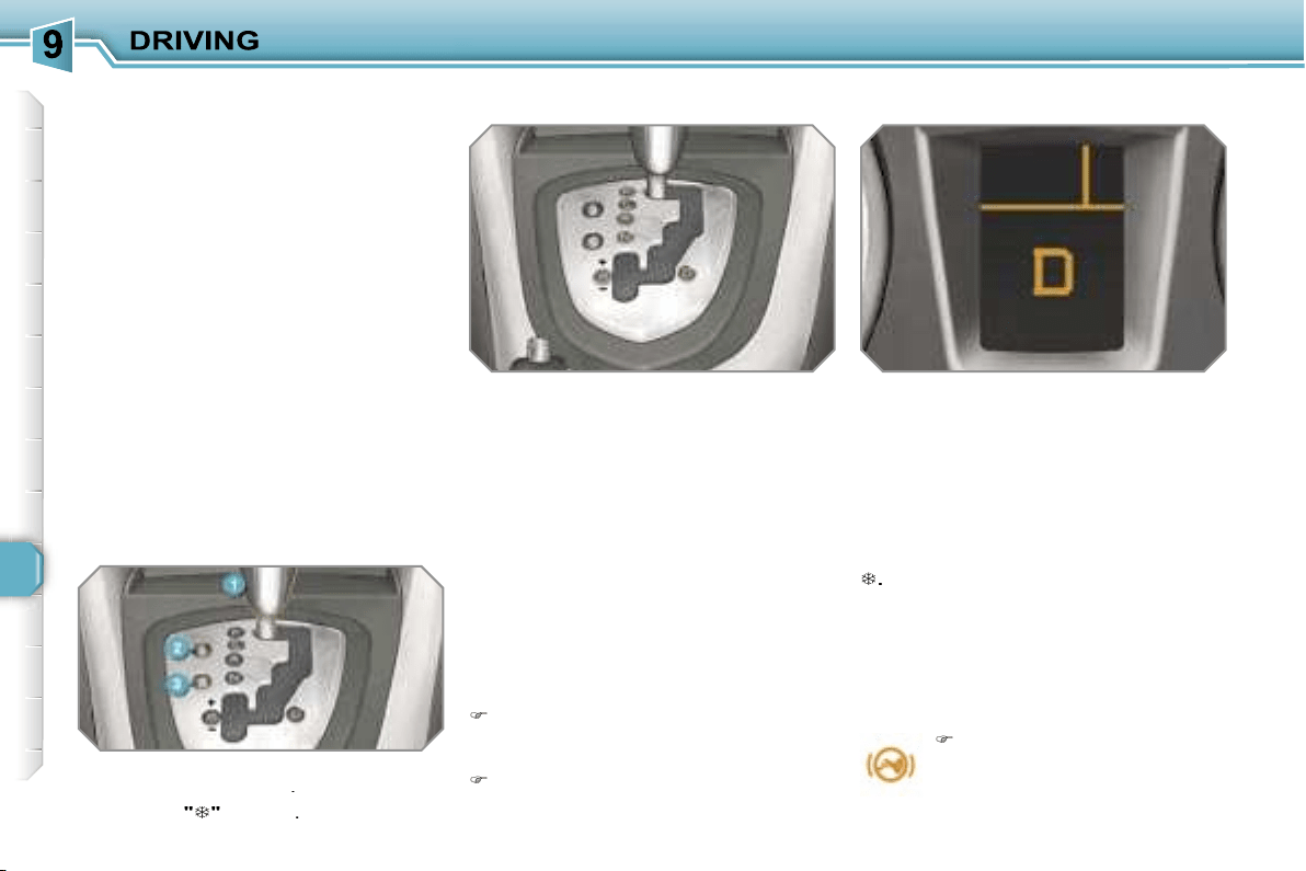
120
"PORSCHE TIPTRONIC
SYSTEM" AUTOMATIC
GEARBOX
Four or six speed automatic gearbox
which offers a choice between the com-
fort of fully automatic operation, en-
hanced by sport and snow programmes,
or manual gear changing.
Therefore, four driving modes are of-
fered:
-
automatic
operation for electronic
management of the gears by the gear-
box,
-
sport
programme for a more dynamic
style of driving,
-
snow
programme to improve driving
when traction is poor,
-
manual
operation for sequential
changing of the gears by the driver.
Gear lever
P.
Park.
- Immobilisation of the vehicle, hand-
brake on or off.
- Starting the engine.
R.
Reverse.
- Reversing manoeuvres, vehicle sta-
tionary, engine at idle.
N.
Neutral.
- Immobilisation of the vehicle, hand-
brake on.
- Starting the engine.
D.
Automatic operation.
M. +/-
Manual operation with sequen-
tial changing of the four or six
gears.
Press forwards to change up through
the gears.
or
Press rearwards to change down
through the gears.
Displays on the instrument panel
When you move the lever in the gate
to select a position, the corresponding
indicator light is displayed on the instru-
ment panel.
P.
Park
R.
Reverse
N.
Neutral
D.
Drive (Automatic driving)
S.
Sport
programme
.
Snow
programme
1 to 4.
Gear engaged during
1 to 6.
manual operation
-.
Invalid value during manual
operation
Press the brake pedal when
this indicator light flashes
(e.g.: starting the engine).
Gear selection gate
1.
Gear lever.
2.
Button
"S"
(sport)
.
3.
Button
"
"
(snow)
.
Foot on brake
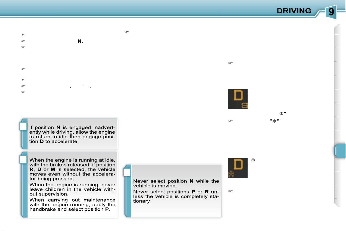
!
!
i
121
Moving off
Apply the handbrake.
Select position
P
or
N
.
Start the engine.
If this procedure is not followed, an au-
dible signal is heard, accompanied by a
message on the multifunction display.
With the engine running, press the
brake pedal.
Release the handbrake.
Select position
R
,
D
or
M
or
or
,
Gradually release the brake pedal.
The vehicle moves off immediately.
The gearbox then operates in auto-
adaptive mode, without any intervention
on the part of the driver. It continuously
selects the most suitable gear accord-
ing to the style of driving, the profile of
the road and the load in the vehicle.
For maximum acceleration without
touching the lever, press the accelera-
tor pedal down fully (kick down). The
gearbox changes down automatically
or maintains the gear selected until the
maximum engine speed is reached.
On braking, the gearbox changes down
automatically to provide efficient engine
braking.
If you release the accelerator sharply,
the gearbox will not change to a higher
gear for safety reasons.
Automatic operation
Select position
D
for
automatic
changing of the four or six gears.
appears on the instrument
panel.
Snow programme "
"
Press button
"
"
, after starting the
engine.
The gearbox adapts to driving on slip-
pery roads.
This programme improves starting and
drive when traction is poor.
S
appears on the instrument
panel.
Sport programme "S"
Press button
"S"
, after starting the
engine.
The gearbox automatically favours a
dynamic style of driving.
Sport and snow programmes
These two special programmes supple-
ment the automatic operation in very
specific conditions of use.
Return to automatic operation
At any time, press the button se-
lected again to quit the programme
engaged and return to auto-adaptive
mode.
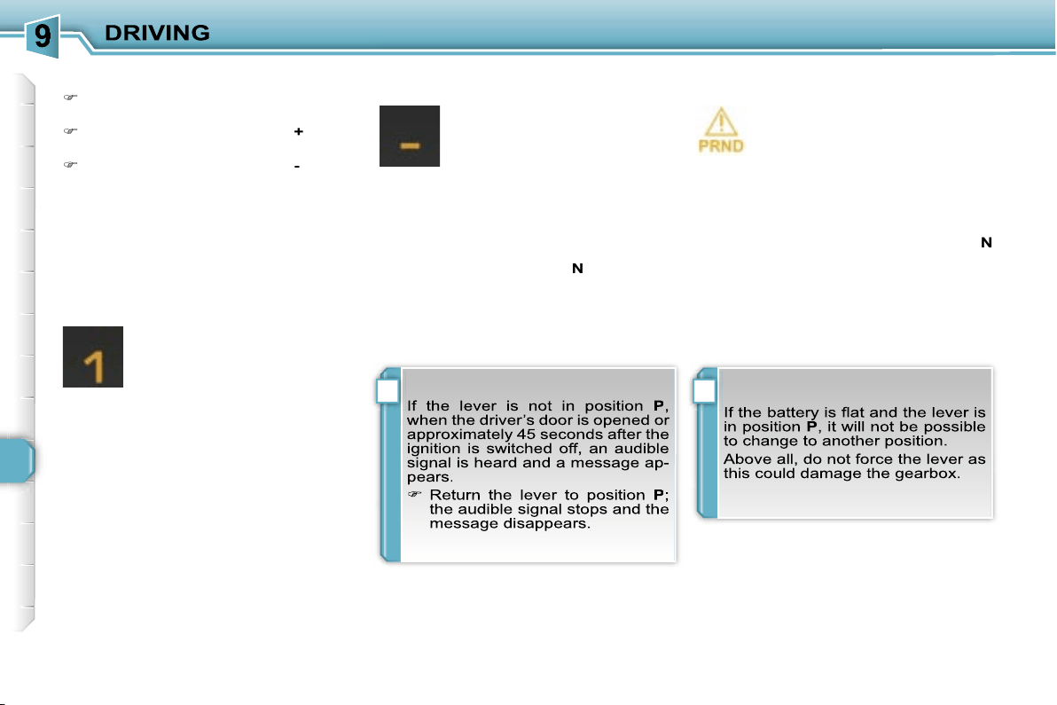
!i
122
Stopping the vehicle
Before switching off the engine, you
can engage position
P
or
N
to place the
gearbox in neutral.
In both cases, apply the handbrake to
immobilise the vehicle.
Operating fault
When the ignition is on, the
lighting of this warning light, ac-
companied by an audible signal
and a message on the multi-
function display, indicates a gearbox
malfunction.
In this case, the gearbox switches to
emergency mode and is locked in 3rd
gear. You may feel a substantial knock
when changing from
P
to
R
and from
N
to
R
. This will not cause any damage to
the gearbox.
Do not exceed 60 mph (100 km/h), local
speed restrictions permitting.
Contact a PEUGEOT dealer as soon as
possible.
Manual operation
Select position
M
for
sequential
changing of the four or six gears.
Push the lever towards the
+
sign to
change up a gear.
Pull the lever towards the
-
sign to
change down a gear.
D
disappears and the gears
engaged appear in succes-
sion on the instrument panel.
In the event of under-revving
or over-revving, the gear se-
lected flashes for a few seconds, then
the actual gear engaged is displayed.
It is possible to change from position
D
(automatic) to position
M
(manual) at
any time.
When the vehicle is stationary or mov-
ing very slowly, the gearbox selects
gear
M1
automatically.
The sport and snow programmes do not
operate in manual mode.
It is only possible to change from one
gear to another if the vehicle speed and
engine speed permit; otherwise, the
gearbox will operate temporarily in au-
tomatic mode.
Invalid value during manual
operation
This symbol is displayed if a
gear is not engaged correctly
(selector between two posi-
tions).
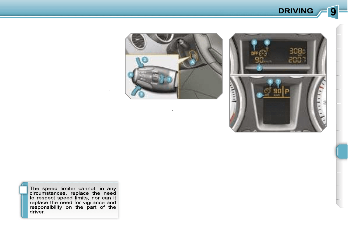
i
123
SPEED LIMITER
System which prevents the vehicle from
exceeding the speed programmed by
the driver.
When the programmed speed limit is
reached, pressing the accelerator pedal
no longer has any effect.
The speed limiter is
switched on
man-
ually: it requires a programmed speed
of at least 20 mph (30 km/h).
The speed limiter is
switched off
by
switched off
switched off
manual operation of the control.
The programmed speed can be ex-
ceeded temporarily by pressing the ac-
celerator firmly.
To return to the programmed speed,
simply slow down to a speed below the
programmed speed.
The programmed speed remains in the
memory when the ignition is switched
off.
The controls of this system are grouped
together on stalk
A
.
1.
Speed limiter mode selection dial
2.
Value decrease button
3.
Value increase button
4.
Speed limiter on/off button
The programmed information is grouped
together on the instrument panel dis-
play.
5.
Speed limiter on/off indication
6.
Speed limiter mode selection
indication
7.
Programmed speed value
Steering wheel controls
Displays on the instrument panel
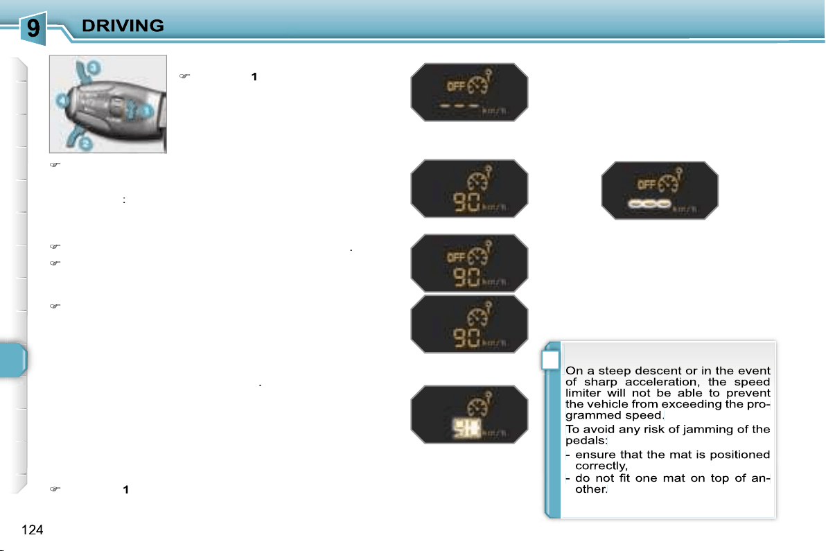
!
Programming
Turn dial
1
to the
"LIMIT"
position:
the speed limiter mode is selected
but is not switched on (OFF).
Exceeding the programmed speed
Pressing the accelerator pedal to exceed the programmed
speed will not have any effect unless you press the pedal
firmly
past the
point of resistance
.
The speed limiter is deactivated temporarily and the pro-
grammed speed, which is still displayed, flashes.
Returning to the programmed speed, by means of intention-
al or unintentional deceleration of the vehicle, automatically
cancels the flashing of the programmed speed.
Return to normal driving
Turn dial
1
to the
"0"
position: the speed limiter mode is
deselected. The display returns to the distance recorder.
Operating fault
In the event of a speed limiter malfunc-
tion, the speed is cleared resulting in
flashing of the dashes.
Contact a PEUGEOT dealer to have the
system checked.
You do not have to switch the speed
limiter on in order to set the speed.
Switch the speed limiter off by pressing button
4
: the dis-
play confirms that it has been switched off (OFF).
Switch the speed limiter back on by pressing button
4
again.
Set the speed value by pressing button
2
or
3
(e.g.:
55 mph (90 km/h)).
You can then change the programmed speed using but-
tons
2
and
3
:
- by + or - 1 mph (km/h) = short press,
- by + or - 5 mph (km/h) = long press,
- in steps of + or - 5 mph (km/h) = maintained press.
Switch the speed limiter on by pressing button
4
.
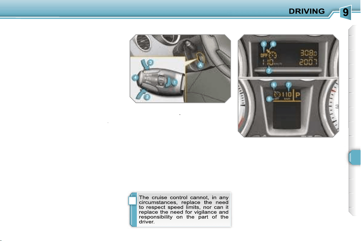
i
125
CRUISE CONTROL
System which automatically maintains
the speed of the vehicle at the value
programmed by the driver, without any
action on the accelerator pedal.
The cruise control is
switched on
manually: it requires a minimum vehicle
speed of 25 mph (40 km/h) and the en-
gaging:
- of fourth gear on the manual gear-
box,
- of second gear on the piloted manual
or automatic gearbox, in sequential
driving mode,
- of position
A
on the piloted manual
gearbox or
D
on the automatic gear-
box.
The cruise control is
switched off
man-
switched off
switched off
ually or by pressing the brake or clutch
pedal or on triggering of the ESP sys-
tem for safety reasons.
It is possible to exceed the programmed
speed temporarily by pressing the ac-
celerator pedal.
To return to the programmed speed,
simply release the accelerator pedal.
Switching off the ignition cancels any
programmed speed value.
The controls of this system are grouped
together on lever
A
.
1.
Cruise control mode selection dial
2.
Speed programming/value
decrease button
3.
Speed programming/value
increase button
4.
Cruise control off/resume button
The programmed information is grouped
together on the instrument panel dis-
play.
5.
Cruise control off/resume
indication
6.
Cruise control mode selection
indication
7.
Programmed speed value
Steering wheel controls
Displays on the instrument panel
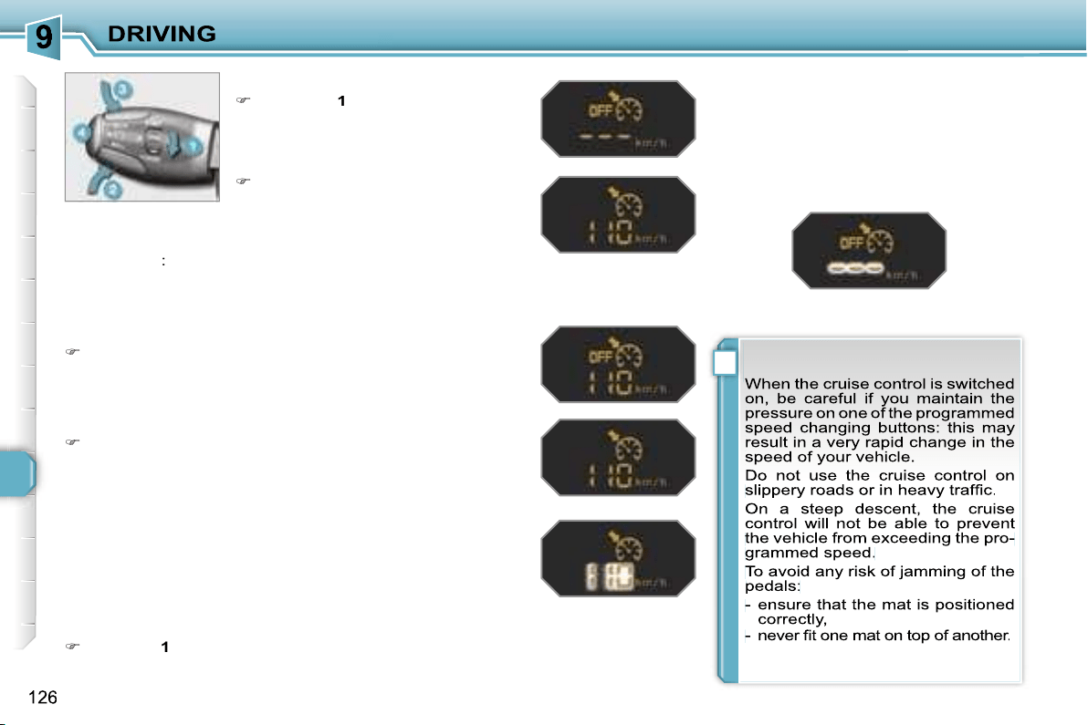
!
Programming
Turn dial
1
to the
"CRUISE"
po-
sition: the cruise control mode is
selected but is not switched on
(OFF).
Exceeding the programmed speed
Intentional or unintentional exceeding of the programmed
speed results in flashing of this speed on the display.
Return to the programmed speed, by means of intentional or
unintentional deceleration of the vehicle, automatically can-
cels the flashing of the speed.
Return to normal driving
Turn dial
1
to the
"0"
position: the cruise control mode is
deselected. The display returns to the distance recorder.
Operating fault
In the event of a cruise control malfunc-
tion, the speed is cleared resulting in
flashing of the dashes.
Contact a PEUGEOT dealer to have the
system checked.
Set the programmed speed by ac-
celerating to the required speed,
then press button
2
or
3
(e.g.:
70 mph (110 km/h)).
Switch off the cruise control by pressing button
4
: the dis-
play confirms that it has been switched off (OFF).
Switch the cruise control back on by pressing button
4
again.
You can then change the programmed speed using but-
tons
2
and
3
:
- by + or - 1 mph (km/h) = short press,
- by + or - 5 mph (km/h) = long press,
- in steps of + or - 5 mph (km/h) = maintained press.
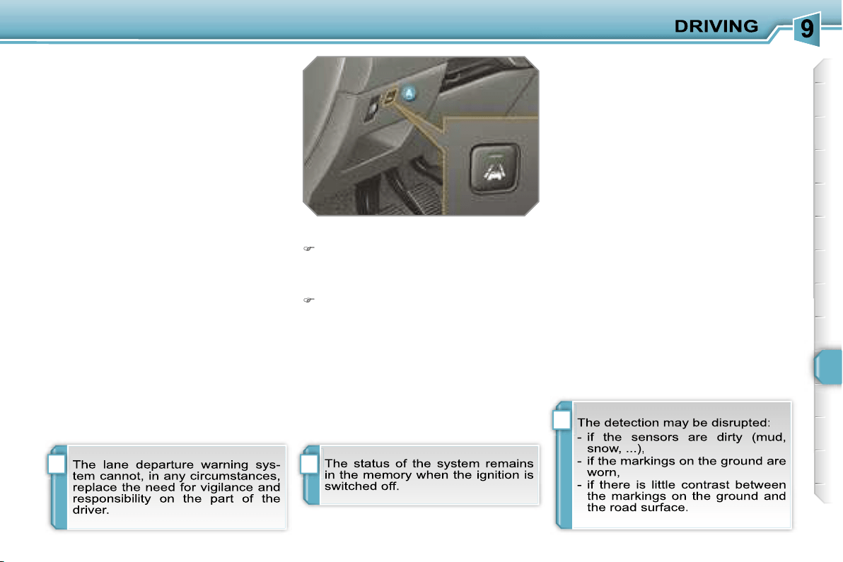
i
i
i
127
LANE DEPARTURE WARNING
SYSTEM
System which detects the involuntary
crossing of longitudinal traffic lane
markings on the ground (continuous or
discontinuous line).
Sensors, fitted below the front bumper,
trigger a warning if the vehicle drifts
(speed higher than 50 mph (80 km/h)).
This system operates to its full potential
above all when used on motorways and
main roads.
Deactivation
Press button
A
again, the indicator
light switches off.
Activation
Press button
A
, the indicator light
comes on.
Operating fault
If the indicator light on the button switches
off while the system is active, this indi-
cates a malfunction.
Contact a PEUGEOT dealer.
Detection
You are warned by vibration of the driv-
er’s seat cushion:
- on the right-hand side, if the marking
on the ground has been crossed on
the right,
- on the left-hand side, if the marking on
the ground has been crossed on the left.
No warning is transmitted while the di-
rection indicator is active and for approx-
imately 20 seconds after the direction
indicator is switched off.
A warning may be transmitted if a direc-
tion marking (arrow) or non-standard
marking (graffiti) is crossed.
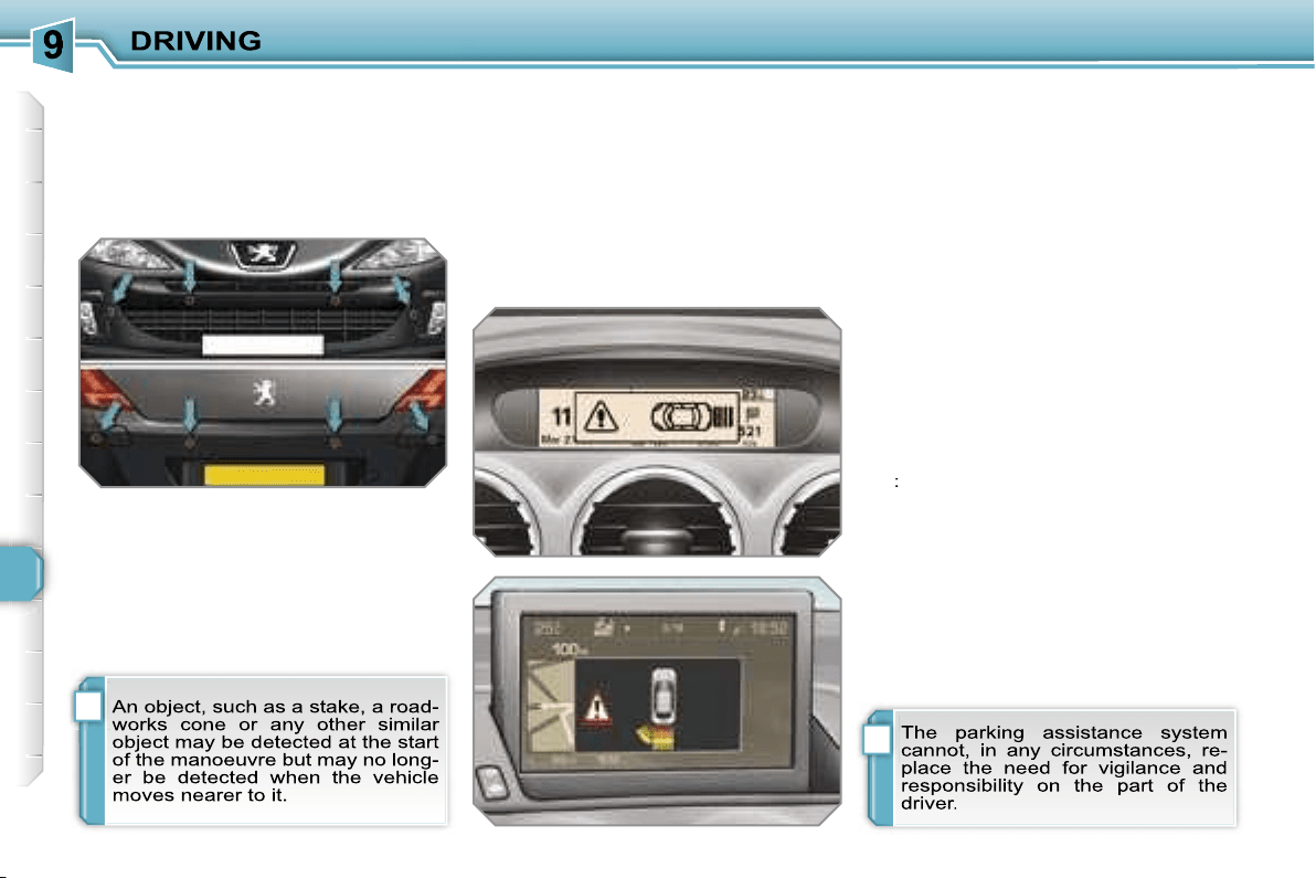
i
i
128
VISUAL AND AUDIBLE FRONT
AND/OR REAR PARKING
ASSISTANCE
System consisting of four proximity sen-
sors, installed in the front and/or rear
bumper.
It detects any obstacle (person, vehicle,
tree, barrier...) located behind the vehi-
cle, however, it will not be able to detect
obstacles located immediately below
the bumper.
The parking assistance is
switched
on
:
- by engaging reverse gear,
- at a speed below 6 mph (10 km/h) in
forward gear.
This is accompanied by an audible sig-
nal and/or displaying of the vehicle on
the multifunction display.
The proximity information is indicated
by:
- an audible signal which becomes
more rapid as the vehicle approaches
the obstacle,
- a diagram on the multifunction display,
with blocks which move closer to the
vehicle.
The obstacle is located in relation to the
emission of the audible signal by the
speakers; front or rear and right or left.
When the distance between the vehicle
and the obstacle is less than approxi-
mately twenty-five centimetres, the au-
dible signal becomes continuous and/or
the "Danger" symbol appears, depend-
ing on the multifunction display version.
The parking assistance is
switched
off
:
- when you exit reverse gear,
- when the speed is higher than 6 mph
(10 km/h) in forward gear,
- when the vehicle has been stationary
for more than three seconds in for-
ward gear.
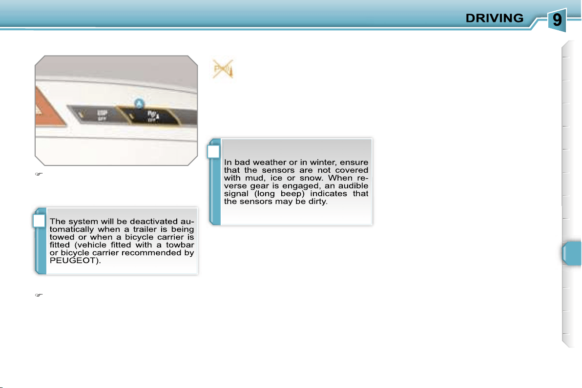
i
i
129
Deactivation
Operating fault
Reactivation
Press button
A
again, the warning
light switches off, the system is reac-
tivated.
Press button
A
, the warning light
comes on, the system is fully deacti-
vated.
If an operating fault occurs, this
warning light is displayed on the
instrument panel and/or a mes-
sage appears on the multifunc-
tion display, accompanied by an audible
signal (short beep), when reverse gear
is engaged.
Contact a PEUGEOT dealer.
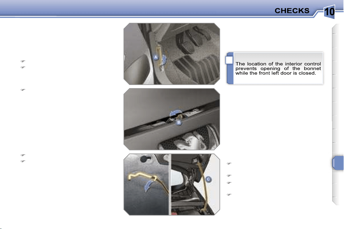
10
i
131
BONNET
Protects the components of the engine
and provides access for checking levels.
Push the exterior control
B
to the left
and raise the bonnet.
Unclip the strut
C
from its housing.
Fix the strut in the notch to hold the
bonnet open.
Closing
Take the strut out of the support
notch.
Clip the strut in its housing.
Lower the bonnet and release it at
the end of its travel.
Pull on the bonnet to check that it is
secured correctly.
Opening
Open the front left door.
Pull the interior control
A
, located at
the bottom of the door frame.
10
i i
132
RUNNING OUT OF FUEL
(DIESEL)
If your vehicle is fitted with an HDI en-
gine, the fuel circuit must be reprimed if
you run out of fuel.
This system consists of a repriming
pump, a transparent pipe and a degas
screw under the bonnet (refer to the
corresponding graphic).
1.6 litre Turbo HDI 16V engine
Fill the fuel tank with at least five
litres of diesel.
Open the bonnet.
Unclip the style cover to gain access
to the repriming pump.
Squeeze and release the repriming
pump until fuel appears in the trans-
parent pipe with the green connector.
Operate the starter until the engine
starts.
Put the style cover back in position
and clip it in place.
Close the bonnet.
2 litre Turbo HDI 16V engine
Fill the fuel tank with at least five
litres of diesel.
Open the bonnet.
Unclip the style cover to gain access
to the repriming pump.
Slacken the degas screw.
Squeeze and release the repriming
pump until fuel appears in the trans-
parent pipe with the green connector.
Retighten the degas screw.
Operate the starter until the engine
starts.
Put the style cover back in position
and clip it in place.
Close the bonnet.
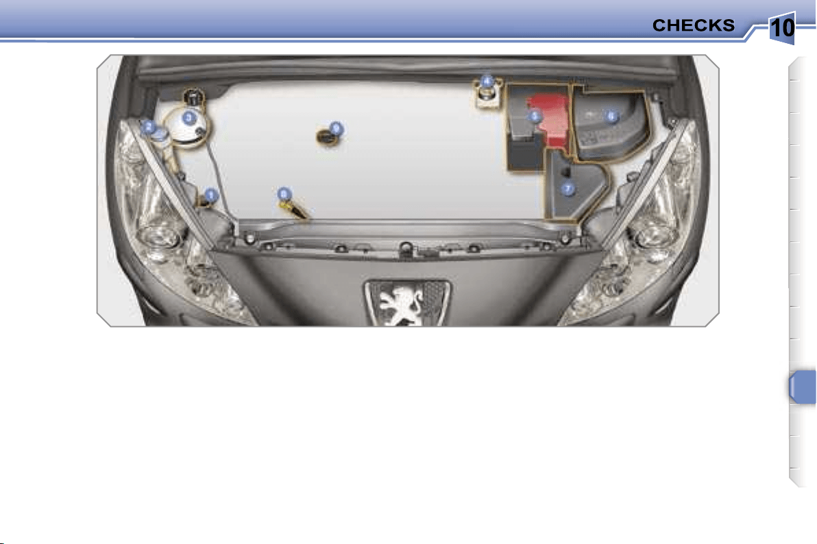
10
133
PETROL ENGINES
They allow you access for checking the level of the various fluids and for replacing certain components.
1.
Power steering reservoir.
2.
Screenwash and headlamp wash
reservoir.
3.
Coolant reservoir.
4.
Brake fluid reservoir.
5.
Battery.
6.
Fuse box.
7.
Air filter.
8.
Dipstick.
9.
Engine oil filler cap.
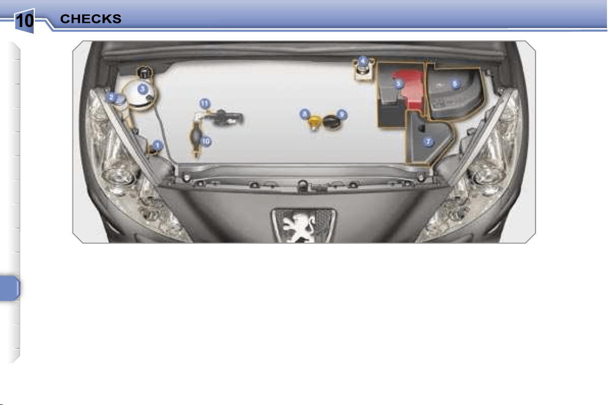
10
134
DIESEL ENGINES
They allow you access for checking the level of the various fluids, for replacing certain components and for repriming the
fuel.
1.
Power steering reservoir.
2.
Screenwash and headlamp wash
reservoir.
3.
Coolant reservoir.
4.
Brake fluid reservoir.
5.
Battery.
6.
Fuse box.
7.
Air filter.
8.
Dipstick.
9.
Engine oil filler cap.
10.
Repriming pump.
11.
Degas screw*.
* According to engine.
10
135
CHECKING LEVELS
Check all of these levels regularly and
top them up if necessary, unless other-
wise indicated.
If a level drops significantly, have the
corresponding circuit checked by a
PEUGEOT dealer.
Brake fluid level
In addition, as the cooling system is
pressurised, wait at least one hour after
switching off the engine before carrying
out any work.
To avoid any risk of scalding, unscrew
the cap by two turns to allow the pres-
sure to drop. When the pressure has
dropped, remove the cap and top up
the level.
Oil level
The reading will only be correct
if the vehicle is on level ground
and the engine has been off for
more than 15 minutes.
The check is carried out either when the
ignition is switched on using the oil level
indicator on the instrument panel, or us-
ing the dipstick.
Between two oil changes, the consump-
tion should not exceed 0.5 litre per
600 miles (1,000 km).
The brake fluid level should be
close to the "MAX" mark. If it is
not, check the brake pad wear.
Draining the circuit
Refer to the servicing booklet for details
of the interval for this operation.
Power steering fluid level
The power steering fluid level
should be close to the "MAX"
mark. Unscrew the cap, with the
engine cold, to check the level.
Screenwash and headlamp
wash fluid
In the case of vehicles fitted
with headlamp washers, the
minimum level of this fluid is
indicated by an audible signal
and a message on the multifunction
display.
Top up the level when you stop the
vehicle.
Draining the engine
Refer to the servicing booklet for details
of the interval for this operation.
In order to maintain the reliability of the
engine and emission control system,
the use of additives in the engine oil is
prohibited.
Oil specification
The oil must correspond to your engine
and conform to the manufacturer’s rec-
ommendations.
Fluid specification
The brake fluid must conform to the
manufacturer’s recommendations and
fulfil the DOT4 standards.
Draining the circuit
The coolant does not have to be
changed.
Fluid specification
For optimum cleaning and to avoid
freezing, this fluid must not be topped
up or replaced with water.
Coolant level
The coolant level should be
close to the "MAX" mark but
should never exceed it.
When the engine is warm, the tempera-
ture of the coolant is regulated by the fan.
This can operate with the ignition off.
On vehicles which are fitted with a
particle emission filter, the fan may
operate after the vehicle has been
switched off, even if the engine is
cold.
Fluid specification
The coolant must conform to the manu-
facturer’s recommendations.

10
!
i
136
Diesel additive level (Diesel with
particle emission filter)
A low additive level is indicated by light-
ing of the service warning light, accom-
panied by an audible warning and a
message on the multifunction display.
Used products
CHECKS
Unless otherwise indicated, check
these components in accordance with
the servicing booklet and in relation to
your engine.
Otherwise, have them checked by a
PEUGEOT dealer.
Battery
The battery does not require
any maintenance.
However, check that the ter-
minals are clean and correctly
tightened, particularly in sum-
mer and winter.
When carrying out work on the battery,
refer to the "Practical information" sec-
tion for details of the precautions to be
taken before disconnecting the battery
and following its reconnection.
Air filter and passenger compartment filter
Refer to the servicing booklet
for details of the replacement
intervals for these components.
Depending on the environment
(dusty atmosphere...) and the
use of the vehicle (city driving...),
replace
them twice as often if necessary
(refer to the "Engines" paragraph).
A clogged passenger compartment filter
may have an adverse effect on the per-
formance of the air conditioning system
and generate undesirable odours.
Particle emission filter (Diesel)
It is imperative that the maintenance of
the particle emission filter is carried out
by a PEUGEOT dealer.
Oil filter
Replace the oil filter each time
the engine oil is changed.
Refer to the servicing booklet
for details of the replacement
interval for this component.
Topping up
This additive must be topped up by a
PEUGEOT dealer without delay.
10
!
137
Brake disc wear status
Brake pads
Handbrake
Brake wear depends on the
style of driving, particularly in
the case of vehicles used in
town, over short distances. It
may be necessary to have the
condition of the brakes checked, even
between vehicle services.
Unless there is a leak in the circuit, a
drop in the brake fluid level indicates
that the brake pads are worn.
For information relating to
checking the brake disc wear
status, contact a PEUGEOT
dealer.
If the handbrake travel is too
long or if a loss of effectiveness
of this system is noticed, the
handbrake must be adjusted,
even between two services.
This system must be checked by a
PEUGEOT dealer.
Manual gearbox
The gearbox does not re-
quire any maintenance (no oil
change).
Refer to the servicing book-
let for the details of the level
checking interval for this com-
ponent.
6-speed piloted manual gearbox
The gearbox does not re-
quire any maintenance (no oil
change).
Refer to the servicing booklet
for details of the checking in-
terval for this component.
Automatic gearbox
The gearbox does not re-
quire any maintenance (no oil
change).
Refer to the servicing booklet
for details of the checking in-
terval for this component.
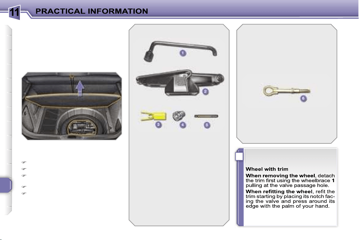
11
i
138
CHANGING A WHEEL
Procedure for changing a faulty wheel
for the spare wheel using the tools pro-
vided with the vehicle.
The tools are installed in the boot under
the floor.
To gain access to them:
open the boot,
raise the floor,
secure it by hooking its cord on the
hook on the rear shelf support,
remove the polystyrene storage box,
unclip and remove the box contain-
ing the tools.
1.
Wheelbrace.
Permits removal of the wheel
trim and removal of the wheel
fixing bolts.
2.
Jack with integral handle.
Permits raising of the vehicle.
3.
"Bolt cover" tool.
Permits removal of the bolt
protectors (covers) on alloy
wheels.
4.
Socket for the anti-theft bolts
(located in the glove box).
Permits adaptation of the
wheelbrace to the special
"anti-theft" bolts.
List of tools
Other accessories
6.
Removable towing eye.
Refer to the paragraph
"Towing the vehicle".
Access to the tools
5.
Centring guide.
Permits the refitting of an alloy
wheel on the hub.
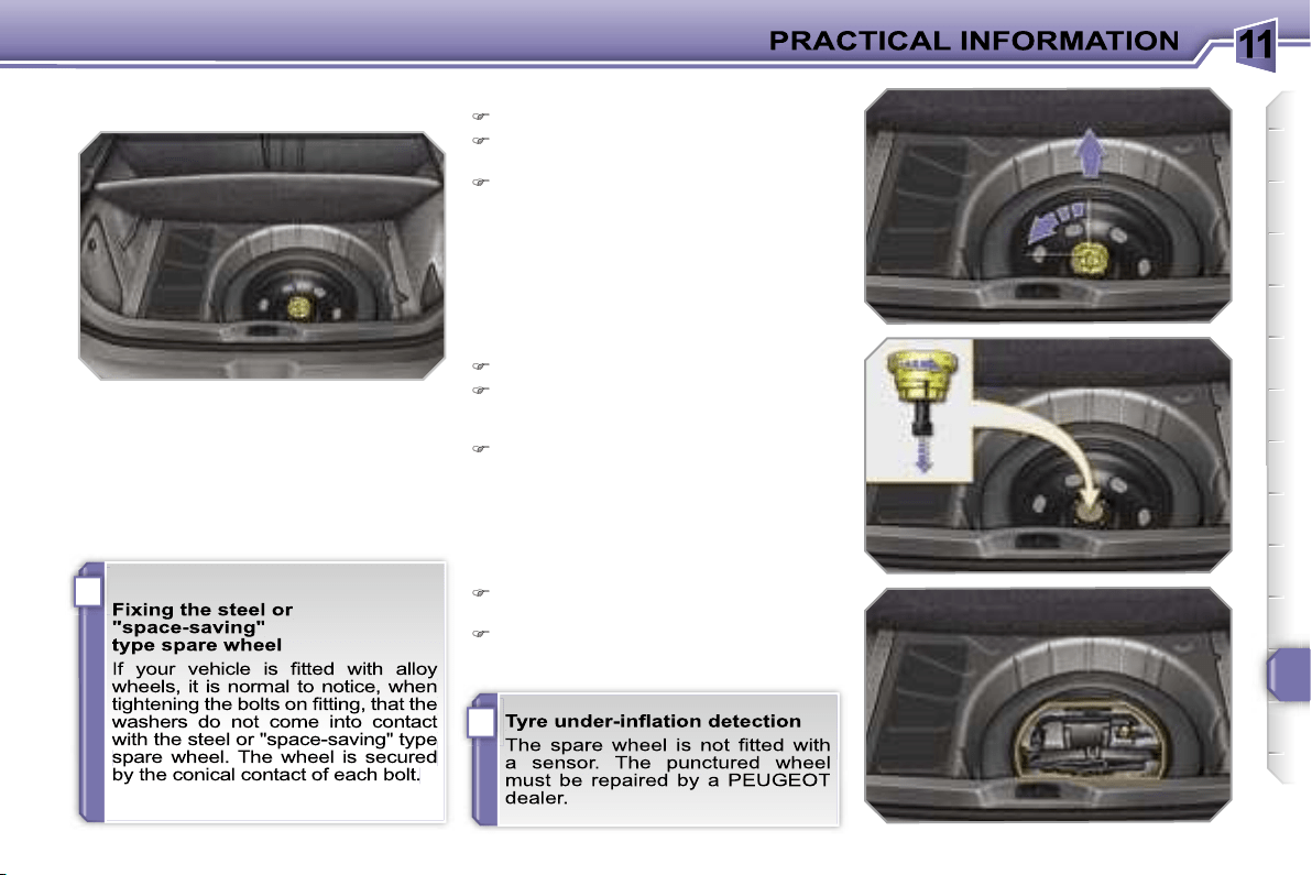
11
i
i
139
Access to the spare wheel
The spare wheel is installed in the boot
under the floor.
According to country, the spare wheel
may be steel, alloy or of the "space sav-
ing" type.
To gain access to it, refer to the para-
graph "Access to the tools" on the previ-
ous page.
Taking out the wheel
Unscrew the yellow central bolt.
Raise the spare wheel towards you
from the rear.
Take the wheel out of the boot.
Putting the wheel back in place
Put the wheel back in its housing.
Unscrew the yellow central bolt by a
few turns then put it in place in the
centre of the wheel.
Tighten fully until the central bolt
clicks to retain the wheel correctly.
Put the box back in place in the cen-
tre of the wheel and clip it.
Put the polystyrene storage box back
in place.
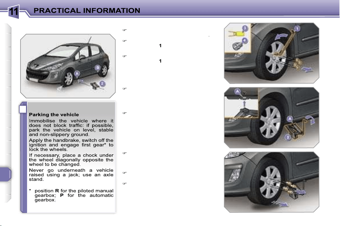
11
i
140
Removing the wheel
List of operations
Remove the chromed bolt cover from
each of the bolts using the tool
3
.
Fit the anti-theft socket
4
on the
wheelbrace
1
to unlock the anti-theft
bolt.
Unlock the other bolts using the
wheelbrace
1
only.
Place the jack
2
in contact with one
of the two front
A
or rear
B
locations
provided on the underframe, which-
ever is closest to the wheel to be
changed.
Extend the jack
2
until its base plate
is in contact with the ground. Ensure
that the centreline of the jack base
plate is directly below the location
A
or
B
used.
Raise the vehicle until there is suf-
ficient space between the wheel and
the ground to admit the spare (not
punctured) wheel easily.
Remove the bolts and store them in
a clean place.
Remove the wheel.
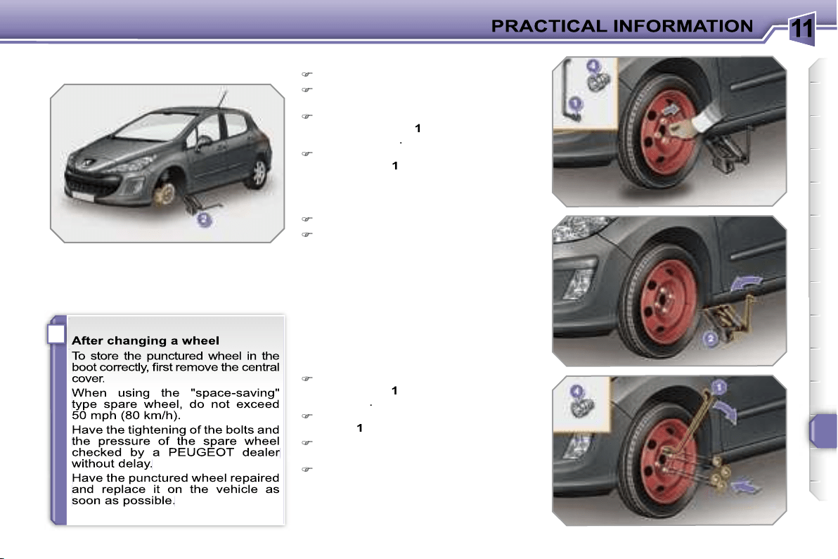
11
i
141
Fitting the wheel
List of operations
Put the wheel in place on the hub.
Screw in the bolts by hand to the
stop.
Pre-tighten the anti-theft bolt using
the wheelbrace
1
fitted with the anti-
theft socket
4
.
Pre-tighten the other bolts using the
wheelbrace
1
only.
Lower the vehicle fully.
Fold the jack
2
and detach it.
Lock the anti-theft bolt using the
wheelbrace
1
fitted with the anti-theft
socket
4
.
Lock the other bolts using the wheel-
brace
1
only.
Refit the chromed bolt covers on
each of the bolts.
Store the tools in the box.
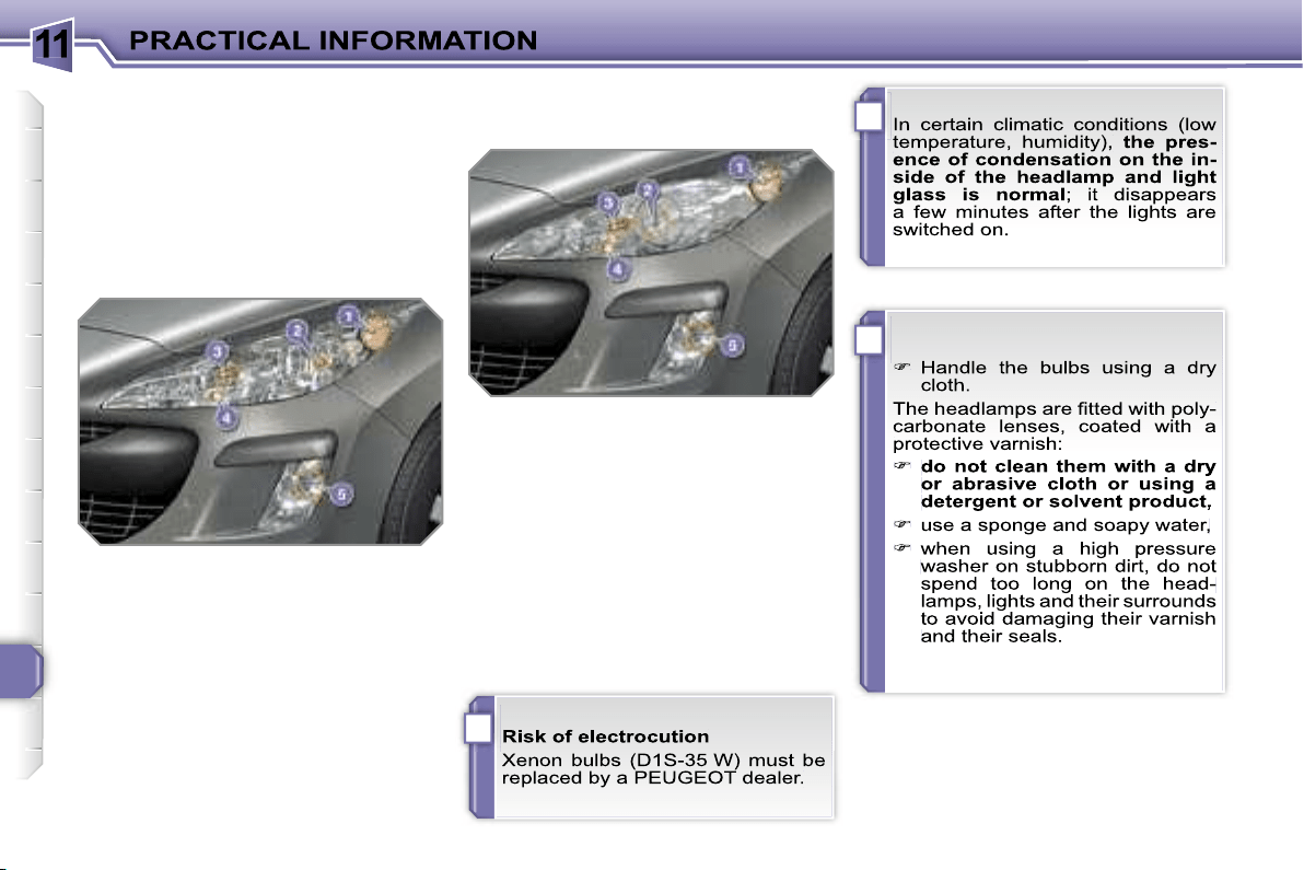
11
i
!
!
142
* According to country.
CHANGING A BULB
Procedure for replacing a faulty bulb with
a new bulb without the use of tools.
Front lights
Model with halogen lights
1. Direction indicators
(PY 21 W amber).
2. Dipped headlamps
(H7-55 W).
3. Main beam headlamps
(H1-55 W).
4. Daytime*/side lights
(P 21/5 W).
5. Fog lamps (H8-35 W).
1. Direction indicators
(PY 21 W SV silver).
2. Dipped/main beam headlamps
(D1S-35 W).
3. Additional main beam
headlamps (H1-55 W).
4. Daytime*/side lights
(P 21/5 W).
5. Fog lamps
(H8-35 W).
Model with xenon lights and
directional headlamps
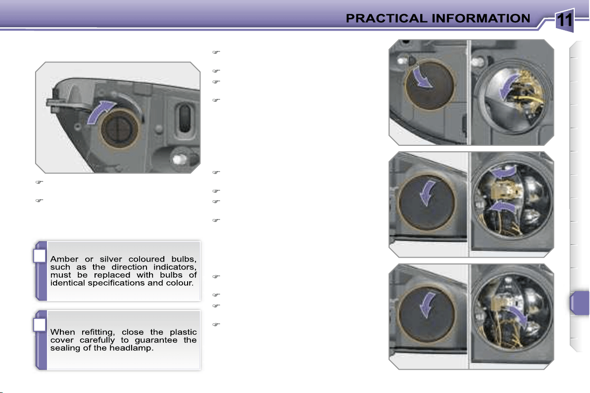
11
i
!
143
Changing main beam headlamp
bulbs
Remove the protective plastic cover
by pulling on the tab.
Disconnect the bulb connector.
Compress the springs to release the
bulb.
Remove the bulb and change it.
To refit, carry out these operations in
reverse order.
Changing daytime/side light bulbs
Remove the protective plastic cover
by pulling on the tab.
Disconnect the bulb connector.
Turn the bulb holder a quarter of a
turn and extract it.
Pull the bulb and change it.
To refit, carry out these operations in
reverse order.
Changing direction indicator bulbs
Turn the bulb holder a quarter of a
turn and extract it.
Pull the bulb and change it.
To refit, carry out these operations in re-
verse order.
Changing dipped headlamp bulbs
Remove the protective plastic cover
by pulling on the tab.
Disconnect the bulb connector.
Compress the springs to release the
bulb.
Extract the bulb and change it.
To refit, carry out these operations in
reverse order.
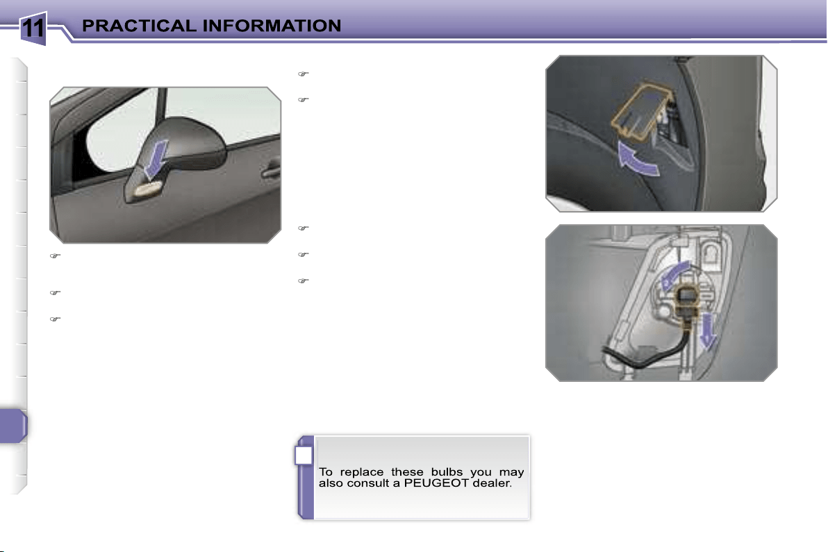
11
i
144
Changing integrated direction
indicator side repeaters
Insert a screwdriver towards the
centre of the repeater between the
repeater and the base of the mirror.
Tilt the screwdriver to extract the
repeater and remove it.
Disconnect the repeater connector.
To refit, carry out these operations in
reverse order.
Contact a PEUGEOT dealer to obtain
replacement repeaters.
Changing fog lamp bulbs
Turn the wheel fully towards the in-
side for easy access to the flap.
Open the access flap, located in the
wheelarch.
Disconnect the bulb holder connec-
tor.
Turn the bulb holder a quarter of a
turn and extract it.
Pull the bulb and change it.
To refit, carry out these operations in re-
verse order.

11
i
145
Rear lights
1. Brake/side lights
(P 21/5 W).
2. Side lights
(P 21/5 W).
3. Fog lamp, left-hand side
(P 21 W).
Reversing light, right-hand side
(P 21 W).
4. Direction indicators
(P 21 W).
Changing bulbs
These five bulbs are changed from out-
side the boot:
remove the two light fixing nuts,
extract the light carefully from the
outside,
disconnect the light connector,
press the four tabs and remove the
bulb holder,
turn the bulb a quarter of a turn and
change it.
To refit, carry out these operations in
reverse order.
on the right-hand side; remove the
access flap,
on the left-hand side; turn the fixing
bolt a quarter of a turn and remove
the storage box cover,
unclip the storage box,
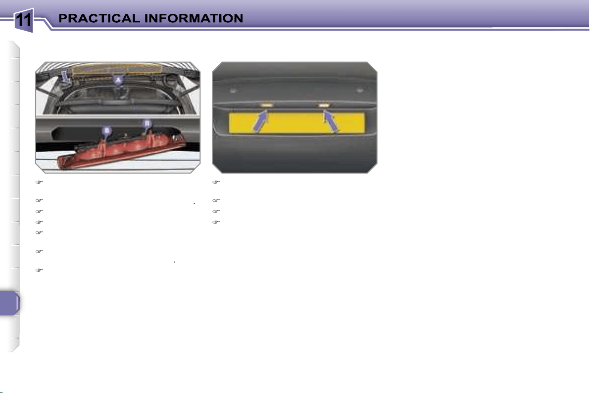
11
146
Changing third brake light bulbs
(4 bulbs W 5 W)
Unclip the tailgate upper trim from
left to right.
Unscrew the two light fixing nuts
A
.
Unclip the light's central pin.
Extract the light from the outside.
Disconnect the bulb holder connec-
tor and the wash-wipe pipe.
Unclip the bulb holder from the light
by pressing on the two tabs
B
.
Pull the bulb and change it.
To refit, carry out these operations in
reverse order.
Do not apply force to the light when
tightening the nuts.
Changing the number plate light
bulbs (W 5 W)
Insert a thin screwdriver into one of
the outer holes of the lens.
Push it outwards to unclip.
Remove the lens.
Pull the bulb and change it.
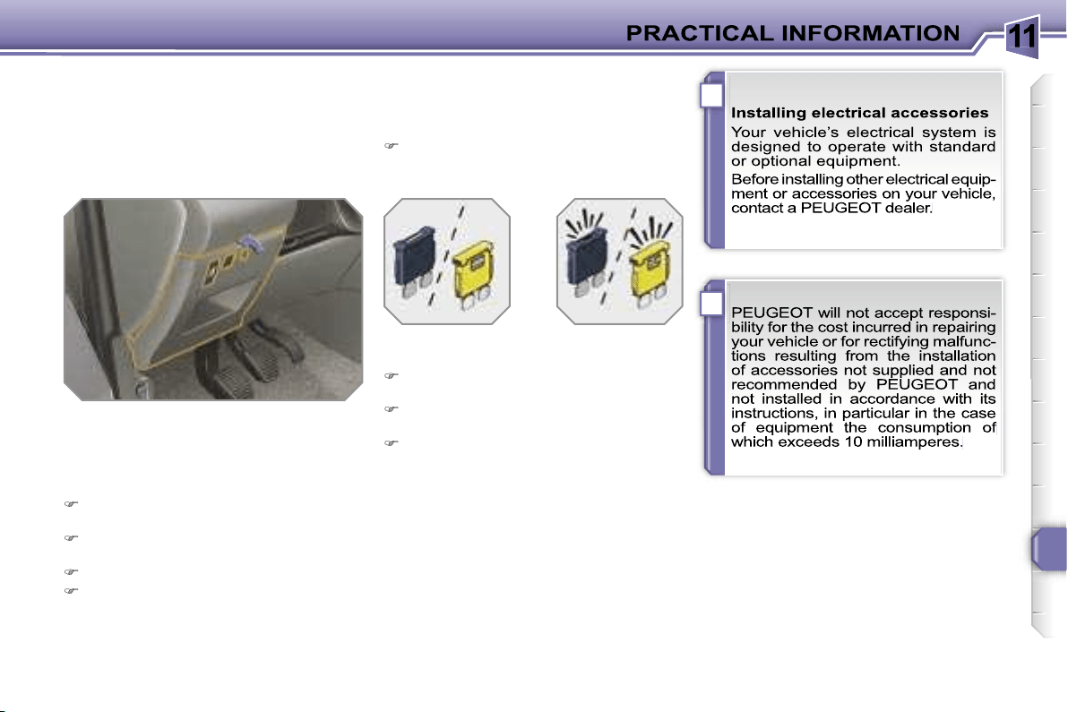
11
!
i
147
CHANGING A FUSE
Procedure for replacing a faulty fuse
with a new fuse to rectify a failure of the
corresponding function.
Access to the tools
The extraction pliers and the spare fus-
es are installed on the back of the fascia
fuse box cover.
To gain access to them:
turn the screw a quarter of a turn to
the left,
unclip the cover by pulling at the top
right,
remove the cover completely,
remove the pliers.
Changing a fuse
Before changing a fuse, the cause of
the failure must be identified and recti-
fied.
Identify the faulty fuse by checking
the condition of its filament.
Use the special pliers to extract the
fuse from its housing.
Always replace the faulty fuse with a
fuse of the same rating.
Check the correspondence between
the number etched on the box, the
rating etched on the fuse and the
tables below.
Correct
Incorrect
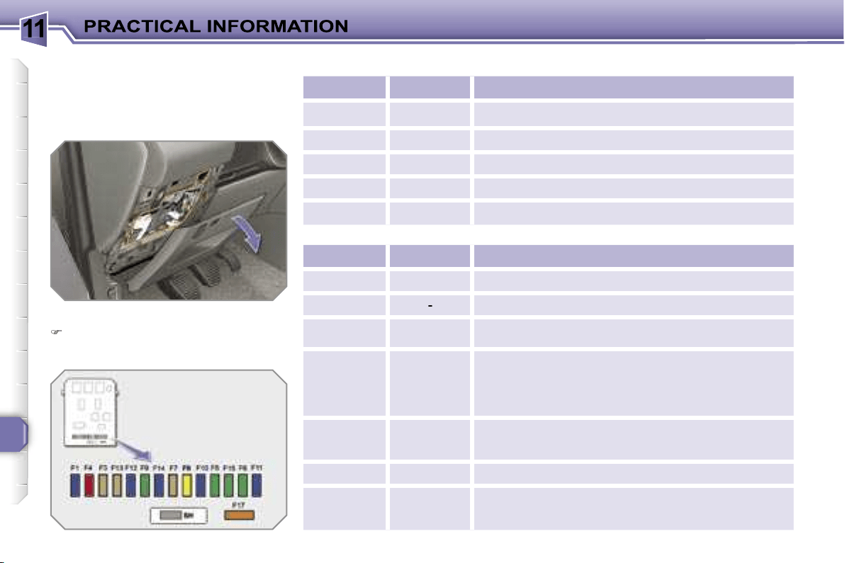
11
148
Fascia fuses
The fuse box is placed in the lower sec-
tion of the fascia (left-hand side).
Access to the fuses
refer to the paragraph "Access to the
tools".
Fuse tables
Fuse N°
Rating
Functions
G36
30 A
Driver and passenger heated seats.
G37
5 A
Trailer fuse box.
G38
30 A
Driver’s seat memory unit.
G39
30 A
Trailer fuse box supply.
G40
30 A
Hi-Fi amplifier.
Fuse N°
Rating
Functions
F1
15 A
Rear wiper.
F2
-
Not used.
F3
5 A
Air bags and pretensioners control unit.
F4
10 A
Clutch pedal and dual-function brake switches,
electrochromatic interior mirror, air conditioning,
steering wheel angle sensor, automatic gearbox,
switching and protection unit.
F5
30 A
Front one-touch electric windows, folding mirrors
supply, glass panoramic roof shutter.
F6
30 A
Rear one-touch electric windows.
F7
5 A
Front and rear courtesy lights, map reading lights,
rear reading lights, sun visor lighting, glove box
lighting.
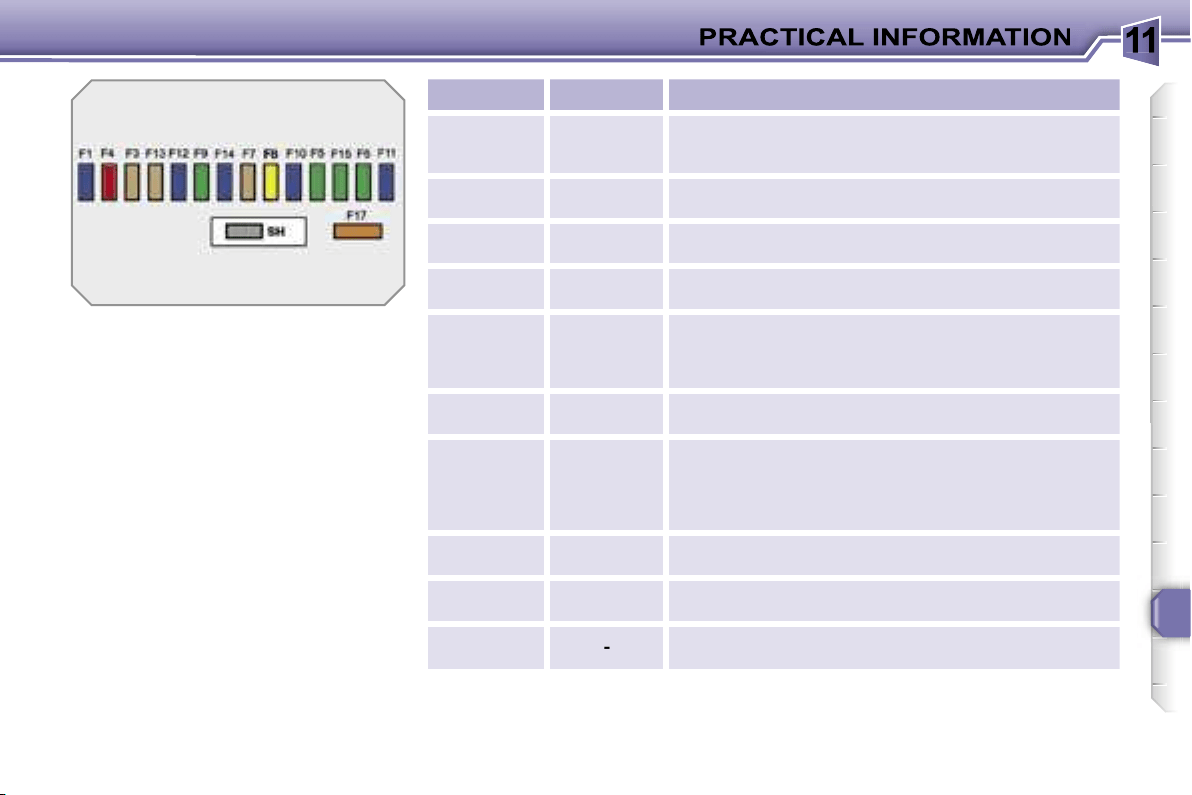
11
149
Fuse N°
Rating
Functions
F8
20 A
Audio equipment, audio/telephone, CD changer,
multifunction display, tyre under-inflation detection.
F9
30 A
Front 12 V socket, lighter.
F10
15 A
Steering wheel controls, alarm siren, alarm control
unit.
F11
15 A
Low current ignition switch.
F12
15 A
Instrument panel, seat belt and passenger’s front
air bag warning lights display, air conditioning,
driver’s seat memory unit, driving school module.
F13
5 A
Engine fuse box, air bags, piloted manual gearbox
gear lever.
F14
15 A
Multifunction display, amplifier, hands-free kit, rain/
brightness sensor, parking assistance control unit,
trailer fuse box, lane departure warning system.
F15
30 A
Locking and deadlocking.
F17
40 A
Rear screen and exterior mirrors de-icing.
SH
-
PARC shunt.
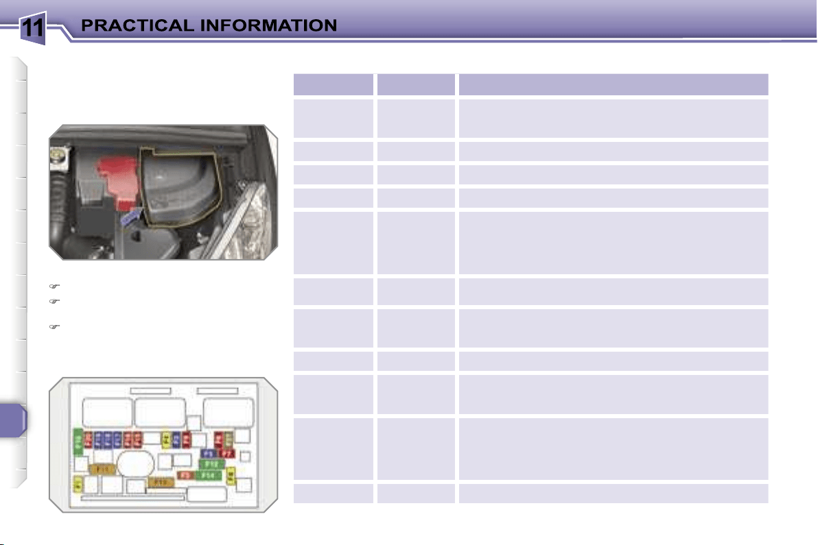
11
150
Engine compartment fuses
The fuse box is placed in the engine
compartment near the battery (left-hand
side).
Access to the fuses
Unclip the cover.
Change the fuse (see corresponding
paragraph).
When you have finished, close the
cover carefully to guarantee the sea-
ling of the fuse box.
Fuse table
Fuse N°
Rating
Functions
F1
20 A
Engine control unit supply, injection pump and
EGR solenoid valves (2 l HDI 16V), injectors
(2 l HDI 16V).
F2
15 A
Horn.
F3
10 A
Front/rear wash-wipe.
F4
20 A
Headlamp wash.
F5
15 A
Fuel pump (petrol), purge canister, turbine
discharge and Turbo pressure regulation solenoid
valves (1.6 l THP 16V), oil vapour heater
(1.6 l THP 16V), diesel heater (1.6 l HDI 16V).
F6
10 A
Vehicle speed sensor, ABS/ESP control unit.
F7
10 A
Power steering control unit, automatic gearbox,
engine coolant level detector.
F8
25 A
Starter control.
F9
10 A
Diagnostic socket, directional headlamps,
air flow sensor (Diesel), particle emission filter
pump (Diesel).
F10
30 A
Engine control unit actuators (petrol: ignition
coils, solenoid valves, oxygen sensors, injectors,
heaters, fuel pump, controlled thermostat)
(Diesel: solenoid valves, heaters).
F11
40 A
Air conditioning blower.
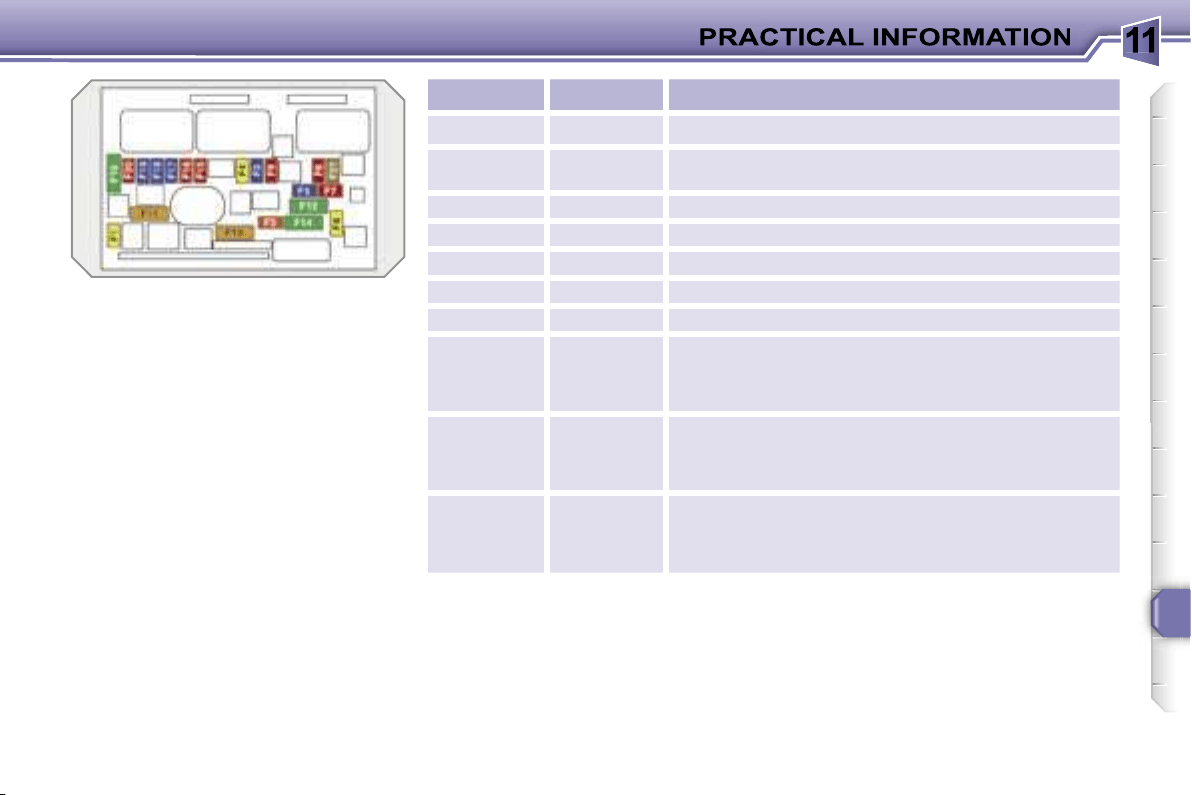
11
151
Fuse N°
Rating
Functions
F12
30 A
Windscreen wipers slow/fast speed.
F13
40 A
Built-in systems interface supply
(ignition positive).
F14
30 A
Air pump.
F15
10 A
Right-hand main beam headlamp.
F16
10 A
Left-hand main beam headlamp.
F17
15 A
Left-hand dipped headlamp.
F18
15 A
Right-hand dipped headlamp.
F19
15 A
Oil vapour heater (1.4 l 16V and 1,6 l VTi 16V),
purge canister solenoid valve (1.4 l 16V and
1.6 l VTi 16V), oxygen sensors (petrol),
air cooling solenoid valves (Diesel).
F20
10 A
Controlled thermostat, variable timing solenoid
valves, Turbo pressure regulation solenoid valve
(Diesel), engine coolant level detector (Diesel).
F21
5 A
Fan assembly relay supply, Valvetronic relay
control (1.4 l 16V and 1.6 l VTi 16V), Turbo cooling
(1.6 l THP 16V), air flow sensor (1.6 l HDI 16V).
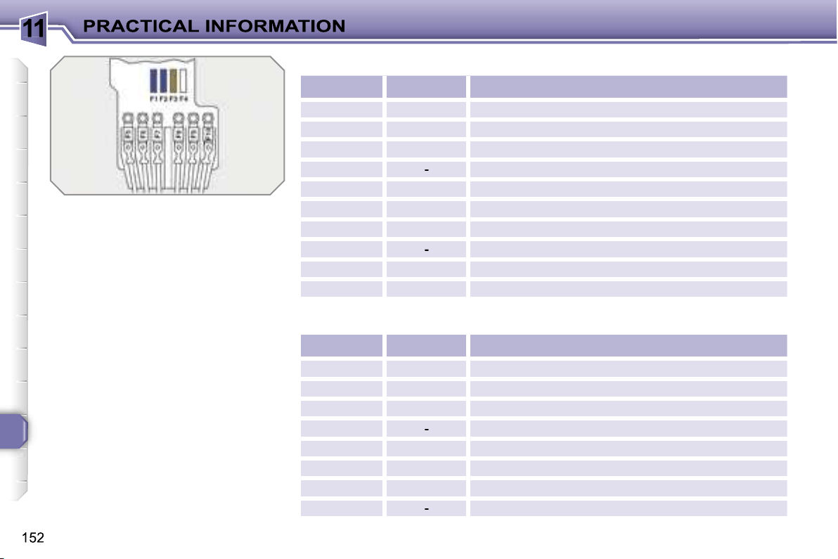
11
Table of mini and midi-fuses above the battery
* The maxi-fuses provide additional
protection for the electrical systems.
All work on the maxi-fuses must be
carried out by a PEUGEOT dealer.
Fuse N°
Rating
Functions
F1
15 A
Gearbox (piloted manual or automatic).
F2
15 A
Diagnostic socket, daytime lights.
F3
5 A
Dual-function brake switch.
F4
-
Not used.
F5*
80 A
Power steering electropump assembly.
F6*
70 A
Heating unit (Diesel).
F7*
100 A
Switching and protection unit.
F8
-
Not used.
F9*
30 A
Piloted manual gearbox electropump assembly.
F10*
30 A
Valvetronic electric motor (1.6 l THP 16V).
Table of maxi-fuses
Fuse N°
Rating
Functions
MF1*
50 A
Fan assembly.
MF2*
50 A
Passenger compartment fuse box.
MF3*
80 A
Built-in systems interface.
MF4*
-
Not used.
MF5*
50 A
ABS/ESP control unit.
MF6*
30 A
ABS/ESP control unit.
MF7*
80 A
Built-in systems interface.
MF8*
-
Not used.
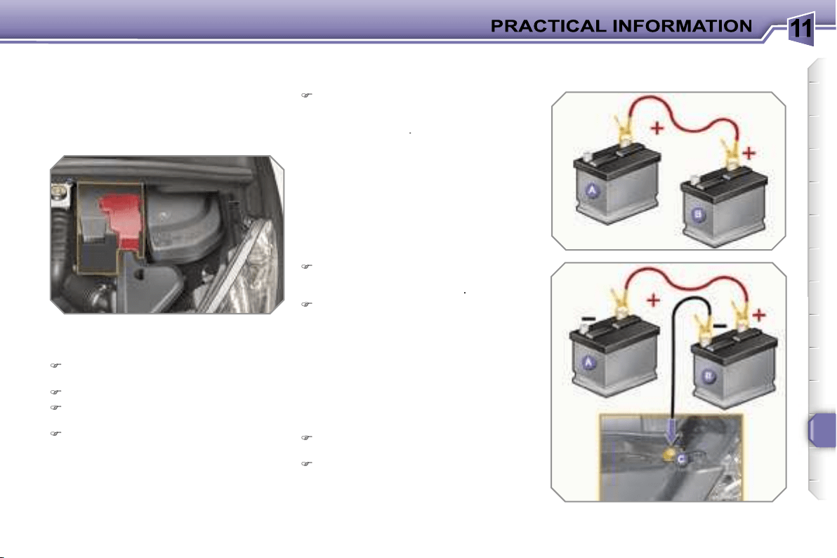
11
153
BATTERY
Procedure for charging your battery
when it is flat or for starting the engine
using another battery.
Access to the battery
Starting using another battery
Connect the red cable to the positive
terminal (+) of the flat battery
A
, then
to the positive terminal (+) of the
slave battery
B
.
Connect one end of the green or
black cable to the negative terminal
(-) of the slave battery
B
.
Connect the other end of the green
or black cable to an earth point
C
on
the broken down vehicle.
Operate the starter, let the engine
run.
Wait until the engine returns to idle
and disconnect the cables.
The battery is located under the bon-
net.
To gain access to it:
open the bonnet using the interior
lever, then the exterior lever,
secure the bonnet strut,
remove the plastic cover to gain
access to the two terminals,
unclip the fuse box to remove the
battery, if necessary.

11
!
!
i
154
Charging the battery using
a battery charger
Disconnect the battery from the vehi-
cle.
Follow the instructions for use pro-
vided by the manufacturer of the
charger.
Reconnect starting with the negative
terminal (-).
Check that the terminals and con-
nectors are clean. If they are covered
with sulphate (whitish or greenish de-
posit), remove them and clean them.
LOAD REDUCTION MODE
System which manages the use of cer-
tain functions in relation to the level of
charge remaining in the battery.
When the vehicle is being driven, the
load reduction function temporarily deac-
tivates certain functions, such as the air
conditioning, the rear screen de-icing...
The deactivated functions are reactivat-
ed automatically as soon as conditions
permit.
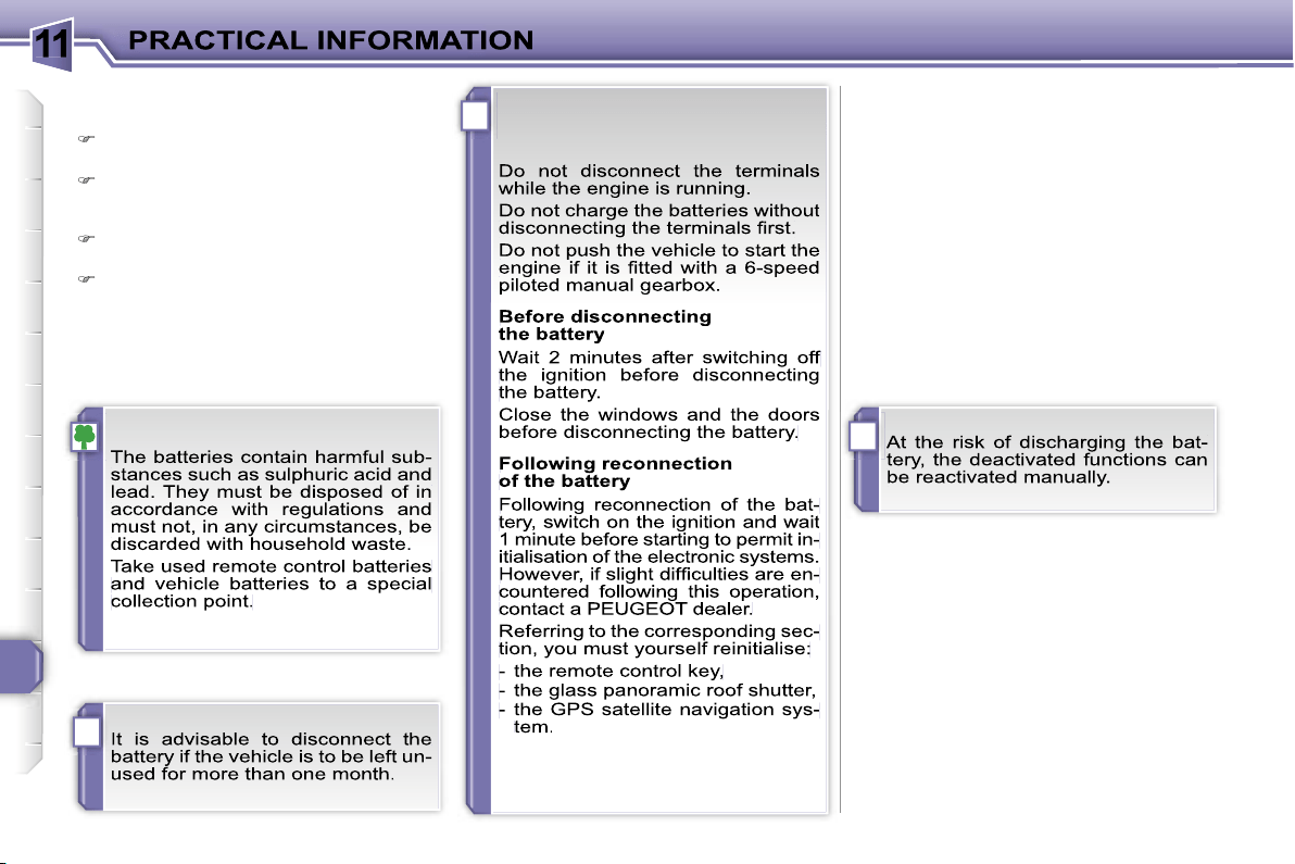
11
!
i
155
ENERGY ECONOMY MODE
System which manages the duration of
use of certain functions to conserve a
sufficient level of charge in the battery.
After the engine has stopped, you can
still use functions such as the audio
equipment, windscreen wipers, dipped
headlamps, courtesy lights, etc. for a
maximum combined duration of thirty
minutes.
Exiting economy mode
These functions are reactivated auto-
matically next time the vehicle is driven.
In order to resume the use of these
functions immediately, start the en-
gine and let it run for a few minutes.
The time available to you will then be
double the duration for which the en-
gine is left running. However, this period
will always be between five and thirty
minutes.
Switching to economy mode
Once the thirty minutes are over, a
message appears on the multifunction
display indicating that the vehicle has
switched to economy mode and the ac-
tive functions are
put on standby.
CHANGING A WIPER BLADE
Procedure for replacing a worn wiper
blade with a new one without the use
of tools.
Removing a front or rear wiper
blade
Raise the corresponding wiper arm.
Unclip the wiper blade and remove it.
Fitting a front or rear
wiper blade
At the front, check the size of the wip-
er blade as the shorter blade is fitted
on the right-hand side of the vehicle.
Put the corresponding new wiper
blade in place and clip it.
Fold down the wiper arm carefully.
Before removing a front wiper
blade
Within one minute after switching off
the ignition, operate the wipers stalk
to position the wiper blades in the
centre of the windscreen.
After fitting a front wiper blade
Switch on the ignition.
Operate the wipers stalk again to
park the wiper blades.
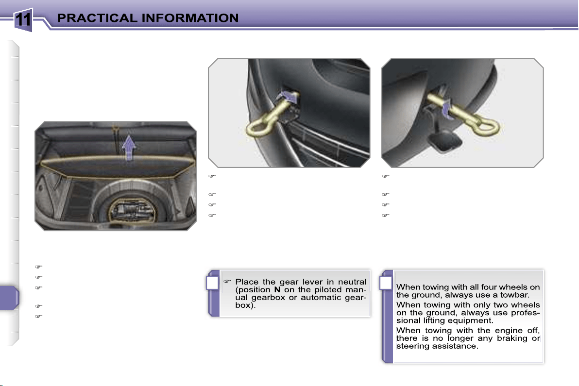
11
!i
156
TOWING THE VEHICLE
Procedure for having your vehicle towed
or for towing another vehicle using a re-
movable towing eye.
Access to the tools
Towing your vehicle
On the front bumper, unclip the cover
by pressing at the bottom.
Screw the towing eye in fully.
Install the towbar.
Switch on the hazard warning lights
on the towed vehicle.
On the rear bumper, unclip the cover
by pressing at the bottom.
Screw the towing eye in fully.
Install the towbar.
Switch on the hazard warning lights
on the towed vehicle.
Towing another vehicle
The towing eye is installed in the boot
under the floor.
To gain access to it:
open the boot,
raise the floor,
secure it by hooking its cord on the
hook on the shelf support,
remove the polystyrene storage box,
remove the towing eye from the holder.
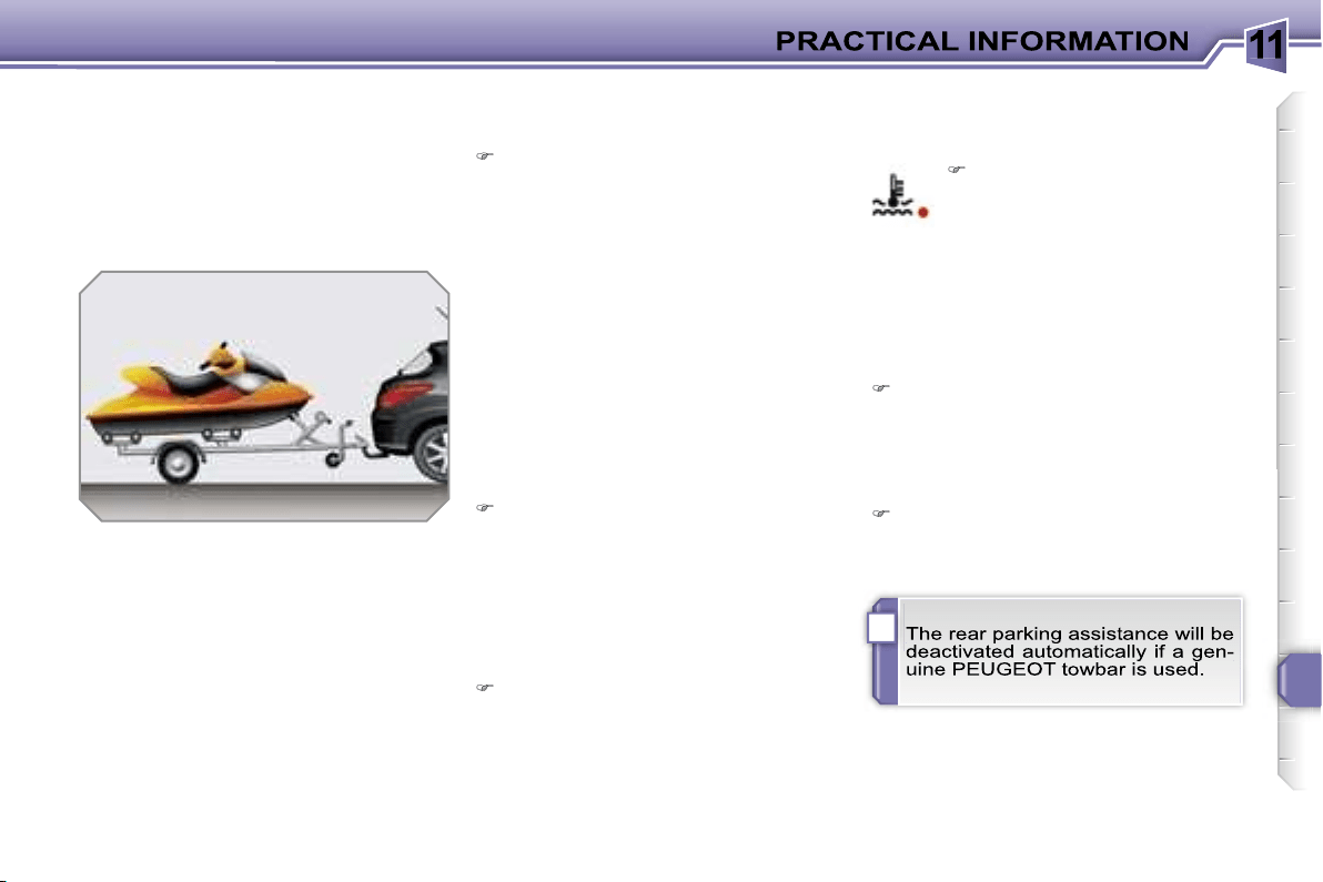
11
i
157
TOWING A TRAILER,
CARAVAN, etc.
Towbar suited to the attachment of a
trailer or caravan with additional signal-
ling and lighting.
Your vehicle is primarily designed for
transporting people and luggage, but it
may also be used for towing a trailer.
We recommend the use of original
PEUGEOT towbars that have been
tested and approved from the design
stage of your vehicle and that the
fitting of the towbar is entrusted to a
PEUGEOT dealer.
Driving with a trailer subjects the towing
vehicle to more significant stress and its
driver must be particularly careful.
Driving advice
Distribution of loads
Distribute the load in the trailer so
that the heaviest items are as close
as possible to the axle and the nose
weight approaches the maximum
permitted without exceeding it.
Air density decreases with altitude, thus
reducing engine performance. Above
1 000 metres, the maximum towing load
must be reduced by 10 % and so on for
every 1 000 metres of altitude.
Refer to the "Technical Data" section for
details of the weights and towing loads
which apply to your vehicle.
In all cases, pay attention to the coolant
temperature.
Side wind
Take into account the increased sen-
sitivity to side wind.
Cooling
Towing a trailer on a slope increases
the temperature of the coolant.
As the fan is electrically controlled, its
cooling capacity is not dependent on
the engine speed.
To lower the engine speed, reduce
your speed.
The maximum towing load on a long
slope depends on the gradient and the
outside temperature.
Braking
Towing a trailer increases the braking
distance.
Tyres
Check the tyre pressures of the tow-
ing vehicle and of the trailer, observ-
ing the recommended pressures.
Lights
Check the electrical signalling on the
trailer.
If the warning light and the
STOP
warning light come
on, stop the vehicle and
switch off the engine as soon
as possible.
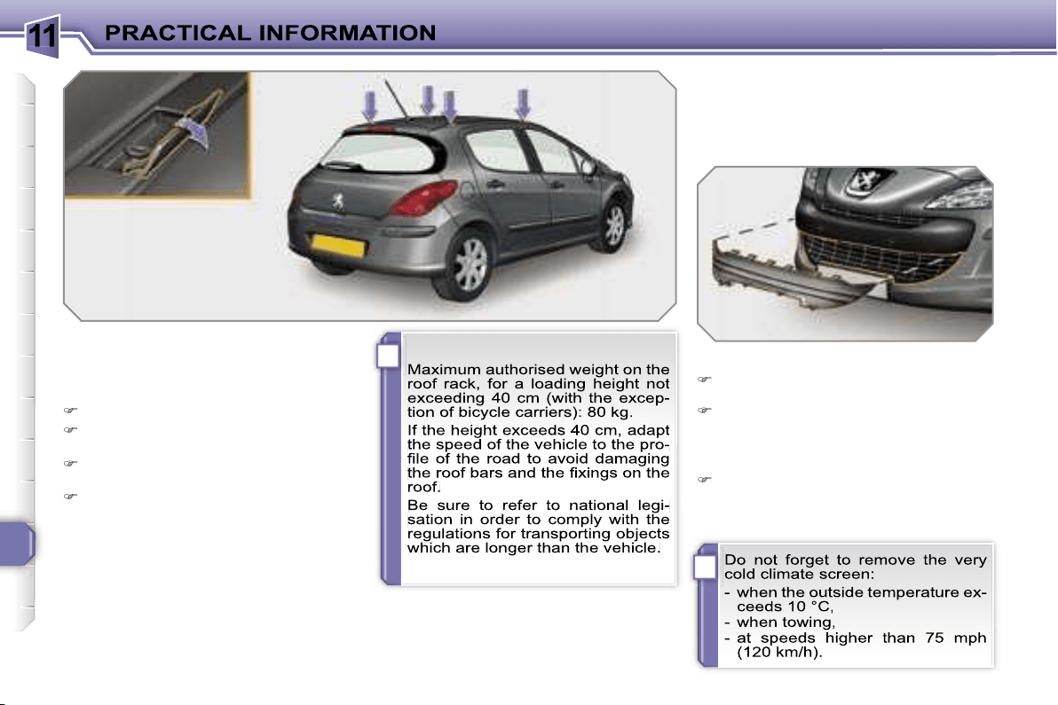
11
i
i
158
FITTING ROOF BARS
When fitting transverse roof bars, use
the four quick-fit fixings provided for this
purpose:
lift the concealing flaps,
open the fixing covers on each bar
using the spanner,
put each fixing in place and lock
them on the roof one by one,
close the fixing covers on each bar
using the spanner.
VERY COLD CLIMATE SCREEN
Removable device which prevents the
accumulation of snow at the radiator
cooling fan.
Fitting
Offer up the very cold climate screen in front
of the lower section of the front bumper.
Press on its periphery to clip its fixing
clips one by one.
* According to country.
Removal
Use a screwdriver as a lever to un-
clip each fixing clip in turn.
11
i
159
ACCESSORIES
You can obtain a wide range of accesso-
ries and original parts from the PEUGEOT
network.
These accessories and parts have been
tested and approved for reliability and
safety.
They are all adapted to your vehicle and
benefit from PEUGEOT’s recommenda-
tion and warranty.
The product range offered by PEUGEOT
Accessories is structured around 5 cate-
gories: PROTECTION - TOURING -
IN-CAR TECHNOLOGY - STYLING -
UNIVERSAL.
"Protection":
"Touring":
"In-car technology":
mats*, boot tray, luggage net,
fixed coat hook on head re-
straint, aluminium or PVC door
sills, fragrance cartridges.
For leisure pursuits: roof bars, bicycle
carrier on towbar, bicycle carrier on roof
bars, ski carrier, roof box, booster seats
and child seats, side blinds and rear
blind, front centre armrest, CD storage,
under shelf storage.
Trailer towbar which must be fitted by
the PEUGEOT network.
audio systems, audio/telephone,
amplifiers, satellite navigation
systems, hands-free kit, CD
changer, speakers, DVD player,
connection kit for MP3 player or
portable CD player, rear parking
assistance.
anti-theft alarm, window en-
graving, wheel locks, first aid
kit, warning triangle, safety
jacket, stolen vehicle tracking
system, snow chains.
*
To avoid any risk of jamming of the pe-
dals:
- ensure that the mat is positioned
and secured correctly,
- never fit one mat on top of another.
11
!
i
160
"Styling":
"Universal" :
You can obtain "Van" conversion kits to
transform a private vehicle into a van.
seat covers compatible with
side air bags, aluminium gear
lever knob, fog lamps, sun-
roof**, door deflectors, spoiler,
styling strips, alloy wheels,
trims, sport exhaust.
screenwash, interior and exte-
rior maintenance and cleaning
products.
** Sunroof which must be fitted by the
PEUGEOT network.
12
161
MODELS:
ENGINES AND GEARBOXES
Model codes:
4C… 4A… 4G...
8FS-C
5FW-C
5FW-F
5FX-C
5FX-F
PETROL ENGINES
1.4 litre 16V
95 bhp
1.6 litre VTi 16V
120 bhp
1.6 litre THP 16V
150 bhp
Cubic capacity (cm
3
)
1 397
1 598
1 598
Bore x stroke (mm)
77 x 75
77 x 85.8
77 x 85.8
Max power: EU standard (kW)
70
88
110
103
Max power engine speed (rpm)
6 000
6 000
5 800
6 000
Max torque: EU standard (Nm)
136
160
240
Max torque engine speed (rpm)
4 250
4 250
1 400
Fuel
Unleaded
Unleaded
Unleaded
Catalytic converter
Yes
Yes
Yes
GEARBOX
Manual
(5-speed)
Manual
(5-speed)
Auto.
(4-speed)
Manual
(5-speed)
Auto.
(4-speed)
OIL CAPACITIES (in litres)
Engine (with cartridge replacement)
4.25
4.25
4.25
4.25
4.25
Gearbox - Final drive
1.9
1.9
-
1.9
-
4C...:
5-door.
4G...:
3-door "Van".
4A...:
3-door.
12
165
MODELS:
ENGINES AND GEARBOXES
Model codes:
4C... 4A... 4G...
9HX-C
9HZ-C
9HZ-H/P
RHR-H
RHR-J
DIESEL ENGINES
1.6 litre Turbo
HDI 16V
90 bhp
1.6 litre Turbo HDI 16V
110 bhp
2 litre Turbo HDI 16V
136 bhp
Cubic capacity (cm
3
)
1 560
1 560
1 997
Bore x stroke (mm)
75 x 88.3
75 x 88.3
85 x 88
Max power: EU standard (kW)
66
80
100
Max power engine speed (rpm)
4 000
4 000
4 000
Max torque: EU standard (Nm)
215
240
320
Max torque engine speed (rpm)
1 750
1 750
2 000
Fuel
Diesel
Diesel
Diesel
Catalytic converter
Yes
Yes
Yes
Particle emission filter
No
Yes
Yes
GEARBOX
Manual
(5-speed)
Manual
(5-speed)
Piloted manual
(6-speed)
Manual
(6 speed)
Auto.
(6 speed)
OIL CAPACITIES (in litres)
Engine (with cartridge replacement)
3.75
3.75
3.75
5.25
5.25
Gearbox - Final drive
1.9
1.9
-
2.4
-
4C...:
5-door.
4G...:
3-door "Van".
4A...:
3-door.

12
162
CONSUMPTION
In accordance with directive 80/1268/CEE
Petrol engines
Gearbox
Model
codes 4C...
4A... 4G...
Urban driving
mpg
(litres/100 km)
Inter-urban
driving mpg
(litres/100 km)
Mixed driving
mpg
(litres/100 km)
Emission of
CO
2
by
weight (g/km)
1.4 litre 16V 95 bhp
Manual
8FS-C
-
-
-
-
1.6 litre VTi 16V 120 bhp
Manual
5FW-C
9.3 5.2 6.7 159
Auto.
5FW-F
- - - -
1.6 litre THP 16V
150 bhp
Manual
5FX-C
9.8 5.6 7.1 167
Auto.
5FX-F
-
-
-
-
The consumption figures shown here correspond to the values communicated at the time of printing.
These consumption values were established in accordance with Directive 80/1268/CEE. They may vary depending on the
style of driving, traffic conditions, weather conditions, the load in the vehicle, the maintenance of the vehicle and the use of
the accessories.
12
166
The consumption figures shown here correspond to the values communicated at the time of printing.
These consumption values were established in accordance with Directive 80/1268/CEE. They may vary depending on the
style of driving, traffic conditions, weather conditions, the load in the vehicle, the maintenance of the vehicle and the use of
the accessories.
CONSUMPTION
In accordance with directive 80/1268/CEE
Diesel engines
Gearbox
Model
codes 4C...
4A... 4G...
Urban driving
mpg
(litres/100 km)
Inter-urban
driving mpg
(litres/100 km)
Mixed driving
mpg
(litres/100 km)
Emission of
CO
2
by weight
(g/km)
1.6 litre Turbo HDI
16V 90 bhp
Manual
9HX-C
-
-
-
-
1.6 litre Turbo HDI
16V 110 bhp
Manual
9HZ-C
6.2 4.1 4.9 130
Piloted
manual
9HZ-H/P
- - - -
2 litre Turbo HDI
16V 136 bhp
Manual
RHR-H
7.2 4.5 5.5 146
Auto.
RHR-J
-
-
-
-

12
163
WEIGHTS AND TOWED LOADS (in kg)
Petrol engines
1.4 litre 16V 95 bhp
1.6 litre VTi 16V 120 bhp
Gearbox
Manual
Manual
Auto.
Model codes:
4C... 4A... 4G...
8FS-C
5FW-C
5FW-F
- Unladen weight
1 271 - 1 262
1 287 - 1 277
1 312 - 1 302
- Kerb weight
1 346 - 1 337
1 362 - 1 352
1 387 - 1 377
- Payload
414 - 412
453 - 450
437 - 435
- Gross vehicle weight (GVW)
1 760 - 1 749
1 815 - 1 802
1 824 - 1 812
- Gross train weight (GTW)
on a 12 % gradient
2 960 - 2 949
3 215 - 3 202
3 094 - 3 082
- Braked trailer (within GTW limit)
on a 10 % or 12 % gradient
1 200
1 400
1 270
- Braked trailer*
(with load transfer within the GTW limit)
1 450
1 650
1 520
- Unbraked trailer
670 - 665
680 - 675
690 - 685
- Recommended nose weight
58
76
61
* The weight of the braked trailer can be increased, within the GTW limit, if the GVW of the towing vehicle is reduced by an
equal amount; warning, towing using a lightly loaded towing vehicle may have an adverse effect on its road holding.
The GTW and towed load values indicated are valid up to a maximum altitude of 1 000 metres; the towed load mentioned
must be reduced by 10 % for each additional 1 000 metres of altitude.
The speed of a towing vehicle must not exceed 60 mph (100 km/h) (comply with the legislation in force in your country).
High exterior temperatures may result in a reduction in the performance of the vehicle to protect the engine; if the exterior
temperature is above 37 °C, limit the towed load.

12
164
* The weight of the braked trailer can be increased, within the GTW limit, if the GVW of the towing vehicle is reduced by an
equal amount; warning, towing using a lightly loaded towing vehicle may have an adverse effect on its road holding.
The GTW and towed load values indicated are valid up to a maximum altitude of 1 000 metres; the towed load mentioned
must be reduced by 10 % for each additional 1 000 metres of altitude.
The speed of a towing vehicle must not exceed 60 mph (100 km/h) (comply with the legislation in force in your country).
High exterior temperatures may result in a reduction in the performance of the vehicle to protect the engine; if the exterior
temperature is above 37 °C, limit the towed load.
WEIGHTS AND TOWED LOADS (in kg)
Petrol engines
1.6 litre THP 16V 150 bhp
Gearbox
Manual
Auto.
Model codes:
4C... 4A...
5FX-C
5FX-F
- Unladen weight
1 327 - 1 314
1 355 - 1 343
- Kerb weight
1 402 - 1 389
1 430 - 1 418
- Payload
424 - 426
425 - 425
- Gross vehicle weight (GVW)
1 826 - 1 815
1 855 - 1 843
- Gross train weight (MTRA)
on a 12 % gradient
3 226 - 3 215
3 255 - 3 243
- Braked trailer (within GTW limit)
on a 10 % or 12 % gradient
1 400
1 400
- Braked trailer*
(with load transfer within the GTW limit)
1 650
1 650
- Unbraked trailer
700 - 690
715 - 705
- Recommended nose weight
66
66
12
167
* The weight of the braked trailer can be increased, within the GTW limit, if the GVW of the towing vehicle is reduced by an
equal amount; warning, towing using a lightly loaded towing vehicle may have an adverse effect on its road holding.
The GTW and towed load values indicated are valid up to a maximum altitude of 1 000 metres; the towed load mentioned
must be reduced by 10 % for each additional 1 000 metres of altitude.
The speed of a towing vehicle must not exceed 60 mph (100 km/h) (comply with the legislation in force in your country).
High exterior temperatures may result in a reduction in the performance of the vehicle to protect the engine; if the exterior
temperature is above 37 °C, limit the towed load.
WEIGHTS AND TOWED LOADS (in kg)
Diesel engines
1.6 litre Turbo HDI 16V 90 bhp
1.6 litre Turbo HDI 16V 110 bhp
Gearbox
Manual
Manual
Piloted manual
Model codes:
4C... 4A... 4G...
9HX-C
9HZ-C
9HZ-H/P
- Unladen weight
1 303 - 1 293
1 322 - 1 312
1 334 - 1 324
- Kerb weight
1 378 - 1 368
1 397 - 1 387
1 409 - 1 399
- Payload
426 - 424
453 - 450
452 - 450
- Gross vehicle weight (GVW)
1 804 - 1 792
1 850 - 1 837
1 861 - 1 849
- Gross train weight (GTW)
on a 12 % gradient
3 074 - 3 062
3 120 - 3 107
3 131 - 3 119
- Braked trailer (within GTW limit)
on a 10 % or 12 % gradient
1 270
1 270
1 270
- Braked trailer*
(with load transfer with the GTW limit)
1 520
1 520
1 520
- Unbraked trailer
685 - 680
695 - 690
700 - 695
- Recommended nose weight
61
61
61
12
168
* The weight of the braked trailer can be increased, within the GTW limit, if the GVW of the towing vehicle is reduced by an
equal amount; warning, towing using a lightly loaded towing vehicle may have an adverse effect on its road holding.
The GTW and towed load values indicated are valid up to a maximum altitude of 1 000 metres; the towed load mentioned
must be reduced by 10 % for each additional 1 000 metres of altitude.
The speed of a towing vehicle must not exceed 60 mph (100 km/h) (comply with the legislation in force in your country).
High exterior temperatures may result in a reduction in the performance of the vehicle to protect the engine; if the exterior
temperature is above 37 °C, limit the towed load.
WEIGHTS AND TOWED LOADS (in kg)
Diesel engines
2 litre Turbo HDI 16V 136 bhp
Gearbox
Manual
Auto.
Model codes:
4C... 4A...
RHR-H
RHR-J
- Unladen weight
1 421 - 1 408
1 447 - 1 434
- Kerb weight
1 496 - 1 483
1 522 - 1 509
- Payload
425 - 427
425 - 426
- Gross vehicle weight (GVW)
1 921 - 1 910
1 947 - 1 935
- Gross train weight (GTW)
on a 12 % gradient
3 621 - 3 610
3 597 - 3 585
- Braked trailer (within GTW limit)
on a 10 % or 12 % gradient
1 700
1 650
- Braked trailer*
(with load transfer within the GTW limit)
1 700
1 650
- Unbraked trailer
745 - 740
750 - 750
- Recommended nose weight
68
66

12
169
DIMENSIONS (in mm)
308 saloon (3 and 5 door versions)
** 5-door.
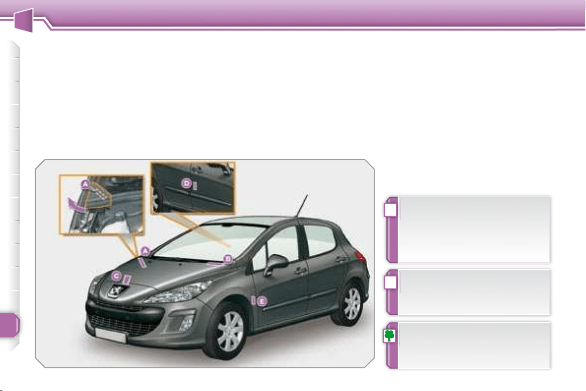
12
!
i
170
TECHNICAL DATA
IDENTIFICATION
FEATURES
Various visible marking elements for the
identifi cation and tracking of your vehi-
cle.
Wheels which are fi tted with 225/45
R17 and 225/40 R18 tyres cannot be
fi tted with snow chains. For further
information, contact a PEUGEOT
dealer.
If the infl ation pressure is too low,
this increases fuel consumption.
The infl ation pressure must be
checked when the tyres are cold,
at least once a month.
A. Chassis number under
the bonnet.
This number is etched on the bodywork
near the damper support.
To gain access to it, raise the plastic
cover.
B. Chassis number on the
windscreen lower crossmember.
This number is indicated on a gummed
label which is visible through the wind-
screen.
C. Manufacturer’s plate.
This plate is riveted onto the engine
mounting.
or
D. Manufacturer’s label.
This number is indicated on a self-de-
stroying label affi xed to the centre pillar,
on the passenger side.
E. Tyre/paint label.
This label is affi xed to the front pillar, on
the driver’s side.
It bears the following information:
- the tyre infl ation pressures with and
without load,
- the wheel rim and tyre sizes,
- the brands of tyre recommended by
the manufacturer,
- the infl ation pressure of the spare
wheel,
- the paint colour reference.
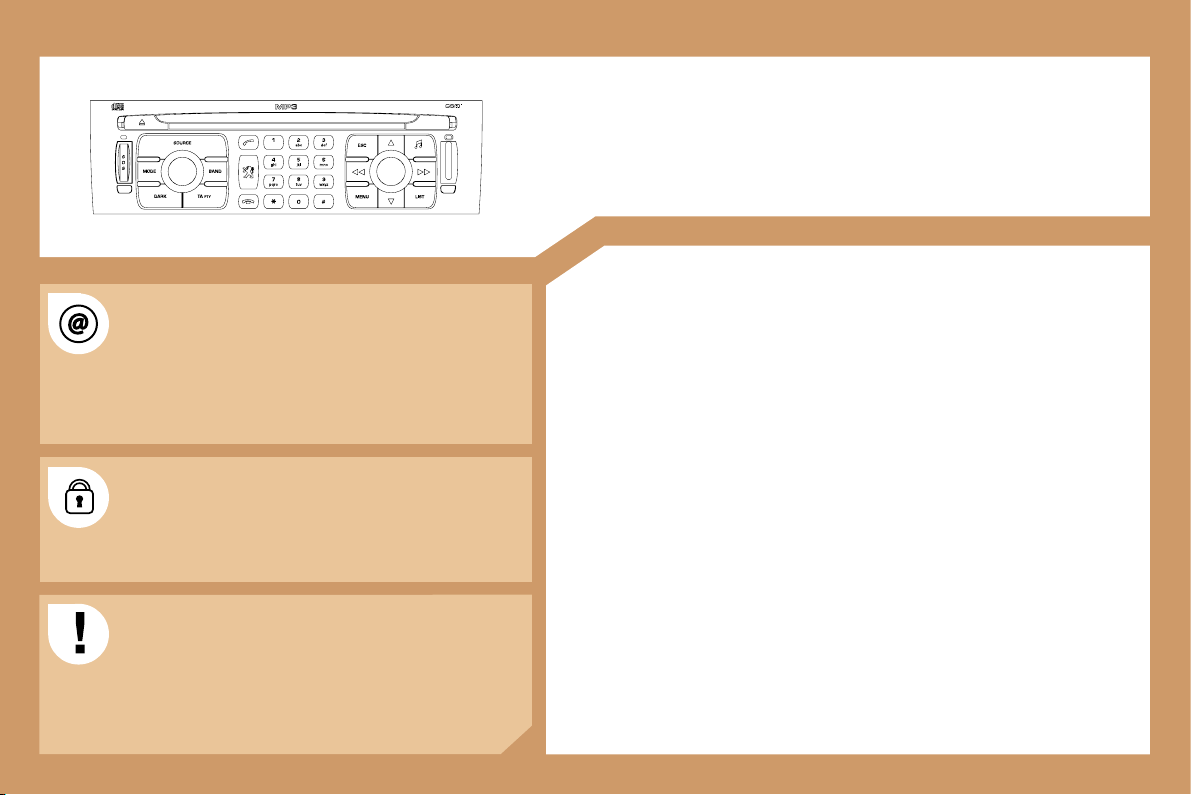
171
RT4
MULTIMEDIA AUDIO EQUIPMENT/TELEPHONE
JUKEBOX FUNCTION (10 GB)/GPS (EUROPE)
Information on the functions offered by this equipment can
be found on the site: http://public.servicebox.peugeot.com
- access is free. From your vehicle’s interactive telematic
guide, make your selection, process, follow the actions
step by step, print.
The RT4 GPS audio/telephone is coded in such a
way that it will only operate in your vehicle. If it is to be
installed in another vehicle, contact your PEUGEOT
dealer for configuration of the system.
For safety reasons, it is imperative that the driver carries
out operations which require prolonged attention while
the vehicle is stationary.
When the engine is switched off and to prevent
discharging of the battery, the RT4 audio/telephone may
switch off after a few minutes.
CONTENTS
• 01 First steps pg. 172
• 02 General menu pg. 173
• 03 GPS pg. 174
• 04 Traffic information pg. 182
• 05 Audio/Video pg. 184
• 06 Telephone pg. 191
• 07 Control short-cuts pg. 194
• 08 Configuration pg. 196
• 09 Display flow charts pg. 197
• Frequently asked questions pg. 213
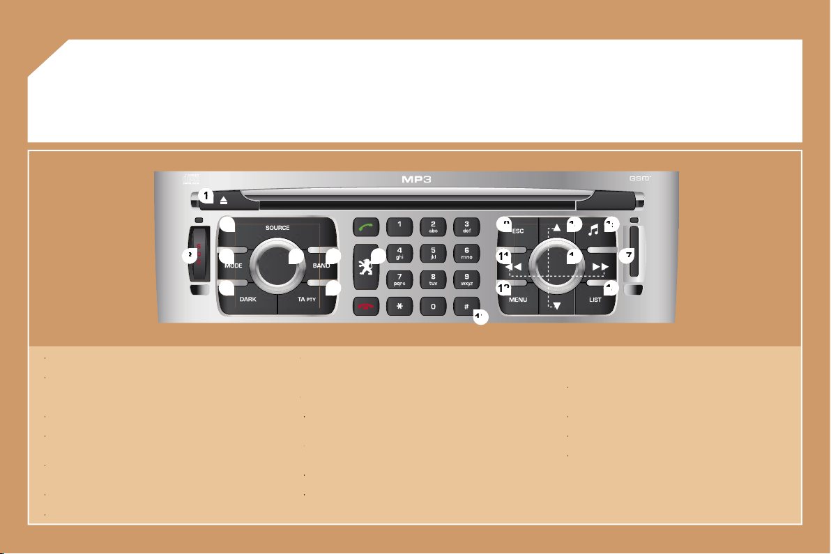
172
2
2
1
1
5
5
3
3
4
4
8
8
9
9
10
10
15
15
11
11
17
17
18
18
12
12
16
16
14
14
7
7
6
6
13
13
01
1 -
Ejection of the CD.
1 -
1 -
2 -
Selection of the source: radio, Jukebox, CD, CD changer and
2 -
2 -
auxiliary (AUX, if activated on the Configuration menu).
Long press: CD copy to hard disc.
3 -
Long press on the SOS button: emergency call.
3 -
3 -
4 -
Selection of the display on the screen from the modes: TRIP,
4 -
4 -
TEL, NAV and AUDIO.
5 -
Modification of the screen display.
5 -
5 -
Long press: reinitialisation of the RT4 GPS audio/telephone.
6 -
On/Off and Volume adjustment.
6 -
6 -
7 -
Selection of the wavebands FM1, FM2, FMast, AM.
7 -
7 -
8 -
TA (Traffic Announcement) function on/off.
8 -
8 -
Long press: access to the PTY (radio Programme TYpes)
mode.
9 -
Access to the "PEUGEOT" services menu.
9 -
9 -
10 -
Cancellation of the current operation.
10 -
10 -
Long press: return to the current application.
11 -
Automatic search for a lower/higher frequency.
11 -
11 -
Selection of the previous/next CD, MP3 or Jukebox track.
12 -
Displaying of the general menu.
12 -
12 -
13 -
Keypad for entering descriptions by successive presses.
13 -
13 -
14 -
Selection of the previous/next CD.
Selection of the previous/next MP3/Jukebox directory.
15 -
Audio option adjustments: front/rear, left/right balance,
15 -
15 -
loudness, sound ambiences.
16 -
Selection and confirmation.
16 -
16 -
17 -
SIM card slot.
17 -
17 -
18 -
Displaying of the list of local radio stations, of the tracks on
18 -
18 -
the CD or of the MP3/Jukebox directories.
Long press: updating of the local radio stations.
FIRST STEPS
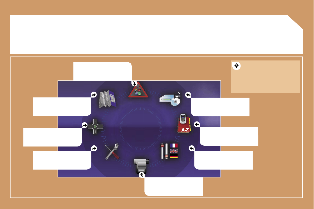
173
02
GENERAL MENU
MAP: orientation, details,
display.
AUDIO FUNCTIONS: radio,
CD, Jukebox, options.
For maintenance of the
display, the use of a
soft, non-abrasive cloth
(spectacles cloth) is
recommended without any
additional product.
TELEMATIC: telephone,
directory, SMS.
CONFIGURATION: vehicle,
display, time, languages,
voice, auxiliary socket (AUX)
parameters.
parameters.
VIDEO: activation, parameters.
VEHICLE DIAGNOSTICS:
warnings log, status of the
functions.
NAVIGATION GUIDANCE:
GPS, stages, options.
TRAFFIC INFORMATION: TMC
information, messages.
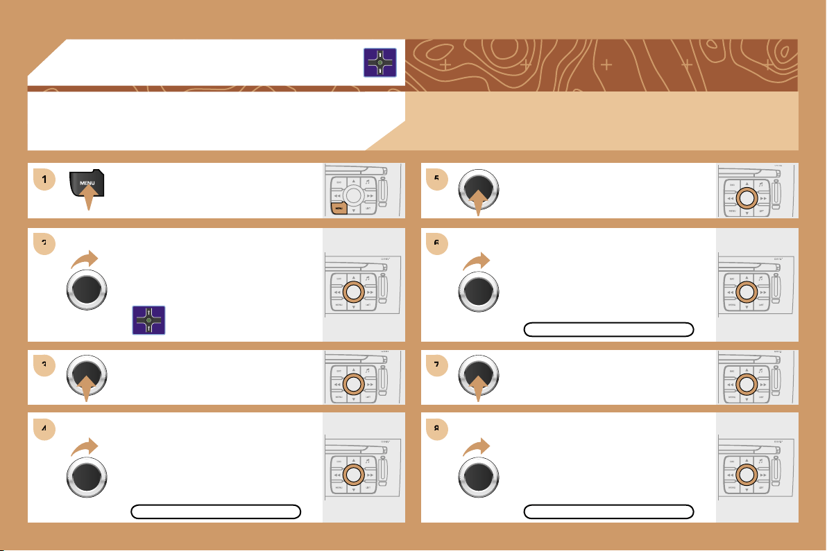
174
1
1
2
2
3
3
5
5
7
7
4
4
6
6
8
8
03
Press the MENU button.
Turn the dial and select the
NAVIGATION GUIDANCE function.
Press the dial to confirm the selection.
Turn the dial and select the
DESTINATION CHOICE function.
Press the dial to confirm the selection.
Press the dial to confirm the selection.
Turn the dial and select the ENTER
AN ADDRESS function.
When the country has been selected,
turn the dial and select the TOWN
function.
TOWN
ENTER AN ADDRESS
DESTINATION CHOICE
Tip: for a detailed global view of the menus available, refer to the "Display flow charts" section of this
RT4 chapter.
GPS
SELECTING A DESTINATION
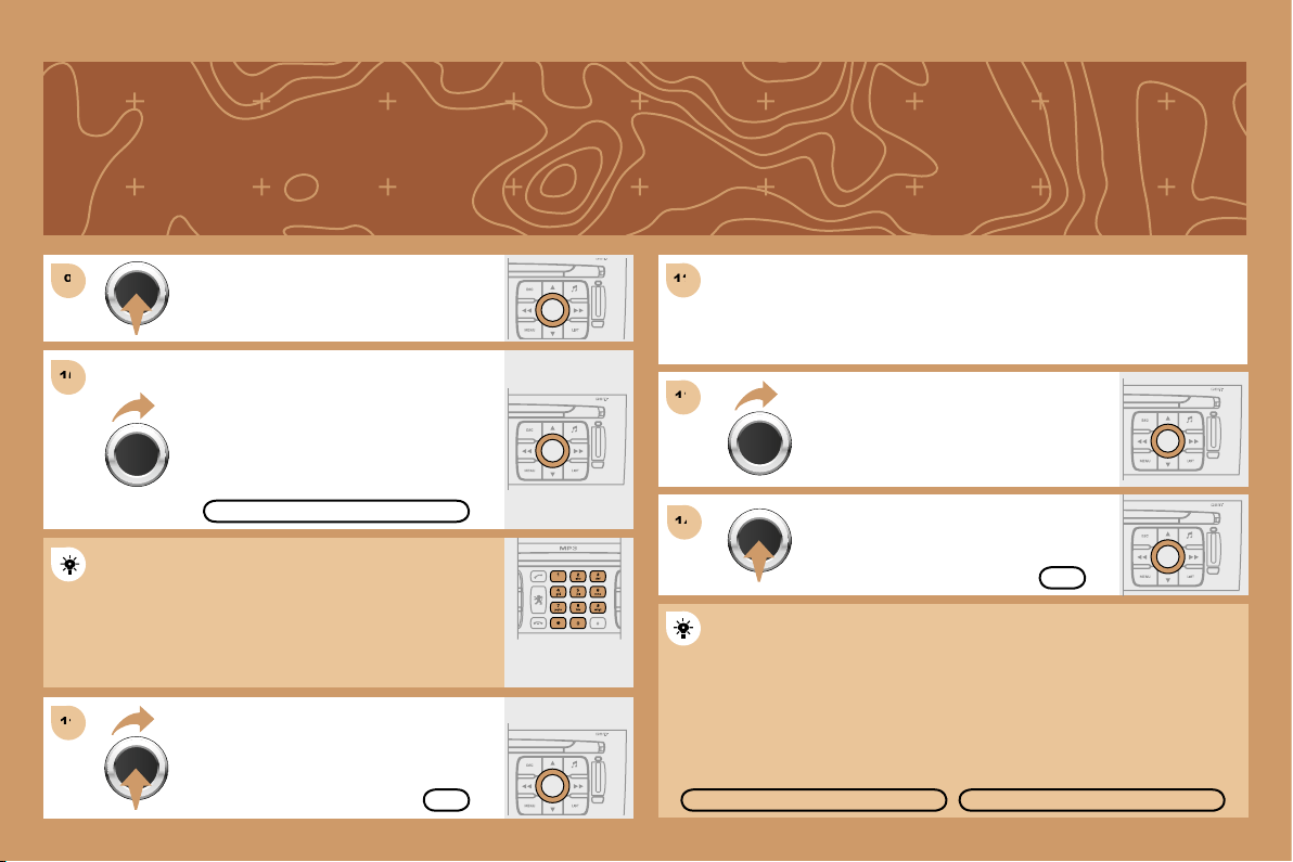
175
9
9
11
11
12
12
14
14
10
10
13
13
Press the dial to confirm the selection.
Turn the dial and select the letters of
the town one by one confirming each
time by pressing the dial.
Select OK and press the dial to
confirm.
To speed up the process, the POST CODE can be
entered instead of the name of the town.
Use the alphanumeric keypad to enter the letters and
digits and "*" to correct.
Press the dial to confirm the selection.
Select OK on the ENTER AN
ADDRESS page.
Repeat steps 8 to 12 for the ROAD and N° functions.
OK
OK
STORE
Select the STORE function to record the address entered in a
directory record and press the dial to confirm the selection.
The points of interest (POI) indicate all of the service locations in the
vicinity (hotels, various businesses, airports...).
POI
PARIS
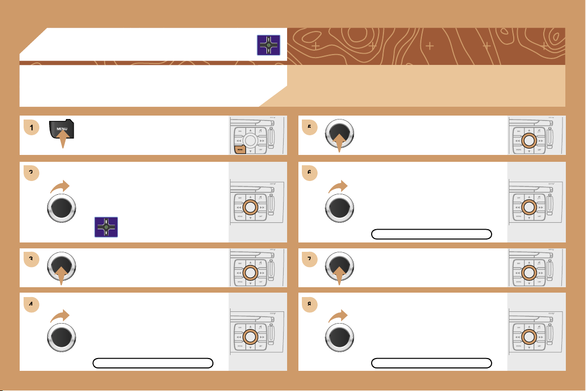
176
1
1
2
2
3
3
4
4
5
5
6
6
7
7
8
8
03
GUIDANCE OPTIONS
GPS
The route chosen by the RT4 GPS audio/telephone depends directly on the guidance options.
Changing these options may completely change the route.
Press the MENU button.
Turn the dial and select the
NAVIGATION GUIDANCE function.
Press the dial to confirm the selection.
Turn the dial and select the
GUIDANCE OPTIONS function.
Turn the dial and select the DEFINE
CALCULATION CRITERIA function.
Press the dial to confirm the selection.
Press the dial to confirm the selection.
DISTANCE/TIME
GUIDANCE OPTIONS
DEFINE CALCULATION CRITERIA
Turn the dial and select, for example,
the DISTANCE/TIME function.
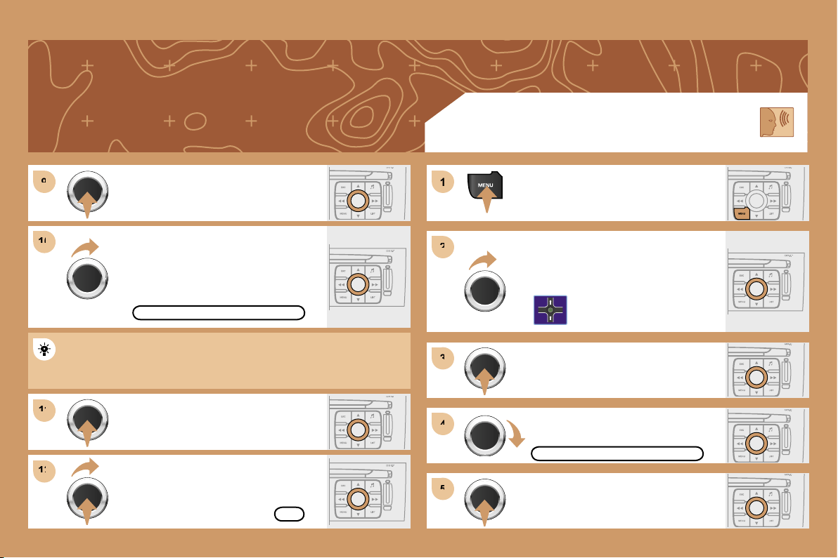
177
9
9
10
10
11
11
12
12
1
1
2
2
3
3
4
4
5
5
Turn the dial and select the TRAFFIC
INFO function if it is not ticked.
Press the dial to confirm the selection.
Select OK and press the dial to
confirm.
TRAFFIC INFO
Press the dial to confirm the selection.
Tick this box for optimum operation of the traffic information,
diversions will be suggested.
OK
GUIDANCE SPEECH SYNTHESIS
Press the MENU button.
Turn the dial and select the
NAVIGATION GUIDANCE function.
Press the dial to confirm the selection.
GUIDANCE OPTIONS
Turn the dial and select the
GUIDANCE OPTIONS function.
Press the dial to confirm the selection.
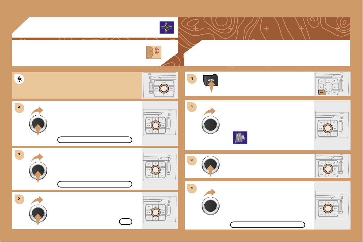
178
6
6
8
8
1
1
2
2
3
3
4
4
7
7
03
Press the MENU button.
Turn the dial and select the MAP
function.
Press the dial to confirm the selection.
Turn the dial and select the MAP
DETAILS function.
Permits selection of the services
which can be seen on the map
(hotels, restaurants...).
ACTIONS ON THE MAP
MAP DETAILS
During the announcements, the volume of each
speech synthesis function (guidance, traffic
information...) can be adjusted directly.
GUIDANCE SPEECH
SYNTHESIS
Select the ADJUST SPEECH
SYNTHESIS function and press the
dial to confirm.
GPS
DEACTIVATE
OK
ADJUST SPEECH SYNTHESIS
Select the DEACTIVATE function and
press the dial to confirm.
Select OK and press the dial to
confirm.
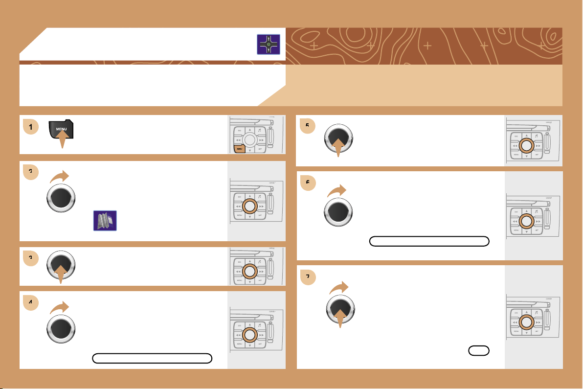
179
1
1
2
2
3
3
4
4
5
5
6
6
7
7
03
For improved visibility, beyond the scale of 10km, the map automatically switches to North Orientation.
Turn the dial and select the MAP
function.
Press the MENU button.
Press the dial to confirm the selection.
Turn the dial and select the 3D VIEW
tab.
Turn the dial and select the MAP
ORIENTATION function.
Press the dial to confirm the selection.
3D VIEW
GPS
OK
3D VIEW
MAP ORIENTATION
Select OK and press the dial to
confirm.
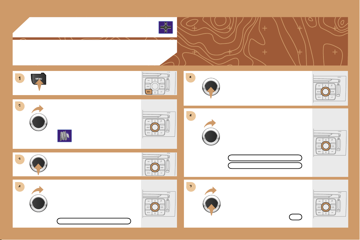
180
1
1
2
2
3
3
4
4
5
5
6
6
7
7
03
Press the MENU button.
Press the dial to confirm the selection.
Turn the dial and select the MAP
function.
Turn the dial and select the MAP IN
WINDOW or FULL SCREEN MAP
tab.
Select OK
and press the dial to
Select OK
Select OK
confirm.
Press the dial to confirm the selection.
Turn the dial and select the DISPLAY
MAP function.
DISPLAYING THE MAP IN A WINDOW OR
IN FULL SCREEN MODE
GPS
OK
FULL SCREEN MAP
DISPLAY MAP
MAP IN WINDOW
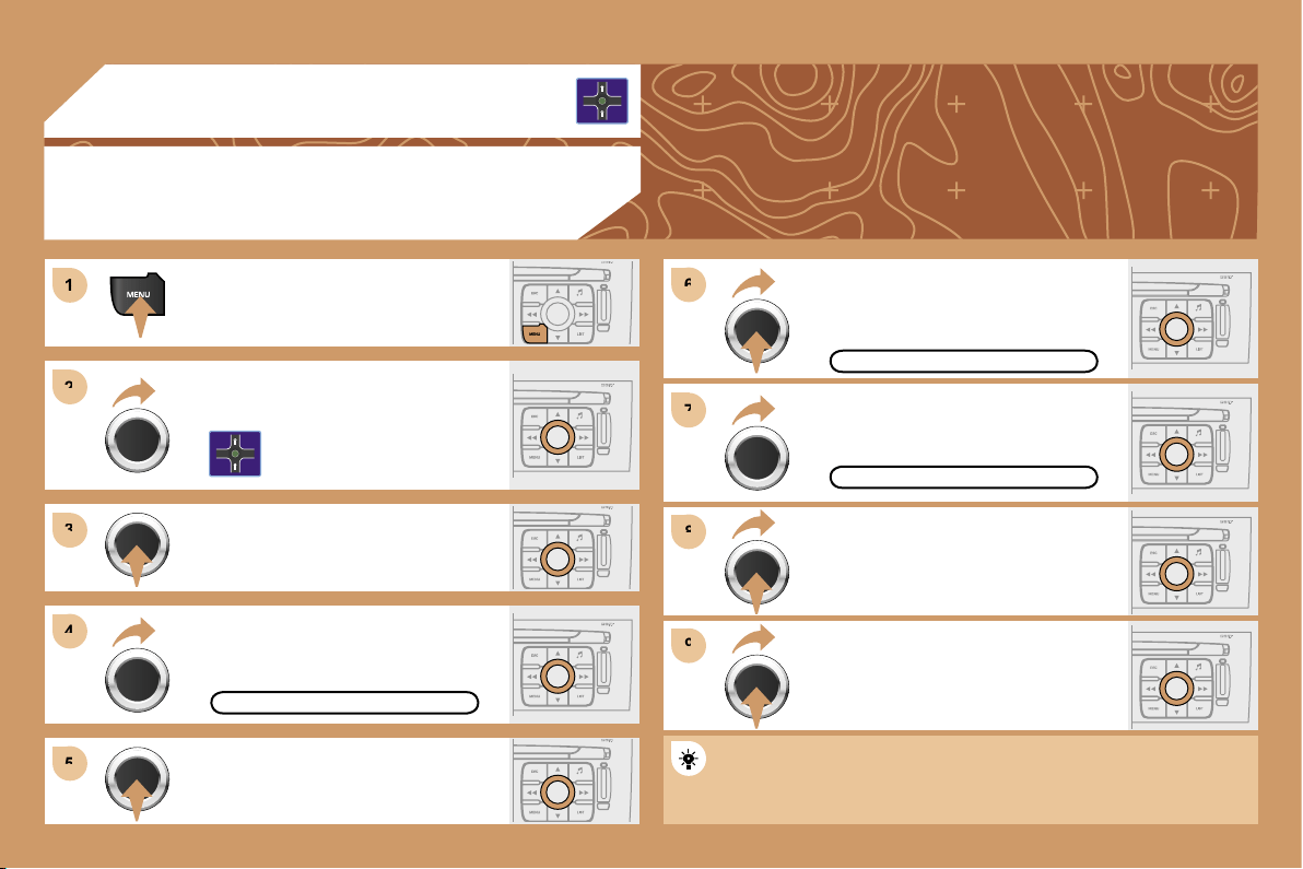
181
1
1
2
2
3
3
4
4
5
5
9
9
8
8
7
7
6
6
03
ADDING A STAGE
During guidance, press the MENU
button.
Turn the dial and select the
NAVIGATION GUIDANCE function.
Press the dial to confirm the selection.
Turn the dial and select the
JOURNEY LEGS AND ROUTE
function.
JOURNEY LEGS AND ROUTE
Select OK and press the dial to
confirm the order of the stages.
When the new address has been
entered, select OK and press the dial
to confirm.
Enter for example a new address.
Select the ADD A STAGE function
(9 stages maximum) and press the
dial to confirm.
ENTER AN ADDRESS
Press the dial to confirm the selection.
ADD A STAGE
The stage must be completed or deleted before the guidance can
continue to the next destination.
Otherwise, the RT4 GPS audio/telephone will always guide you
back to the previous stage.
GPS
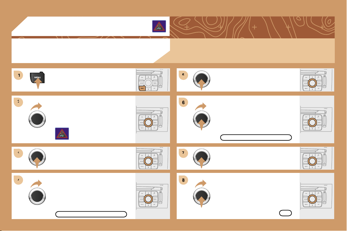
182
1
1
2
2
3
3
4
4
5
5
6
7
7
8
04
ACTIVATING THE FILTER ON THE ROUTE
We recommend a filter on the route and a filter around the vehicle of:
- 5 km or 10 km for a region with heavy traffic,
- 20 km for a region with a normal level of traffic,
- 100 km for long journeys (motorway).
Press the MENU button.
Turn the dial and select the TRAFFIC
INFORMATION function.
Press the dial to confirm the selection.
FILTER TRAFFIC INFORMATION
GEOGRAPHIC FILTER
Turn the dial and select the FILTER
TRAFFIC INFORMATION function.
OK
Press the dial to confirm the
selection.
Select the GEOGRAPHIC FILTER
function and press the dial to confirm.
Turn the dial and select the ON THE
ROUTE tab.
TRAFFIC INFORMATION
Select OK and press the dial to
confirm.
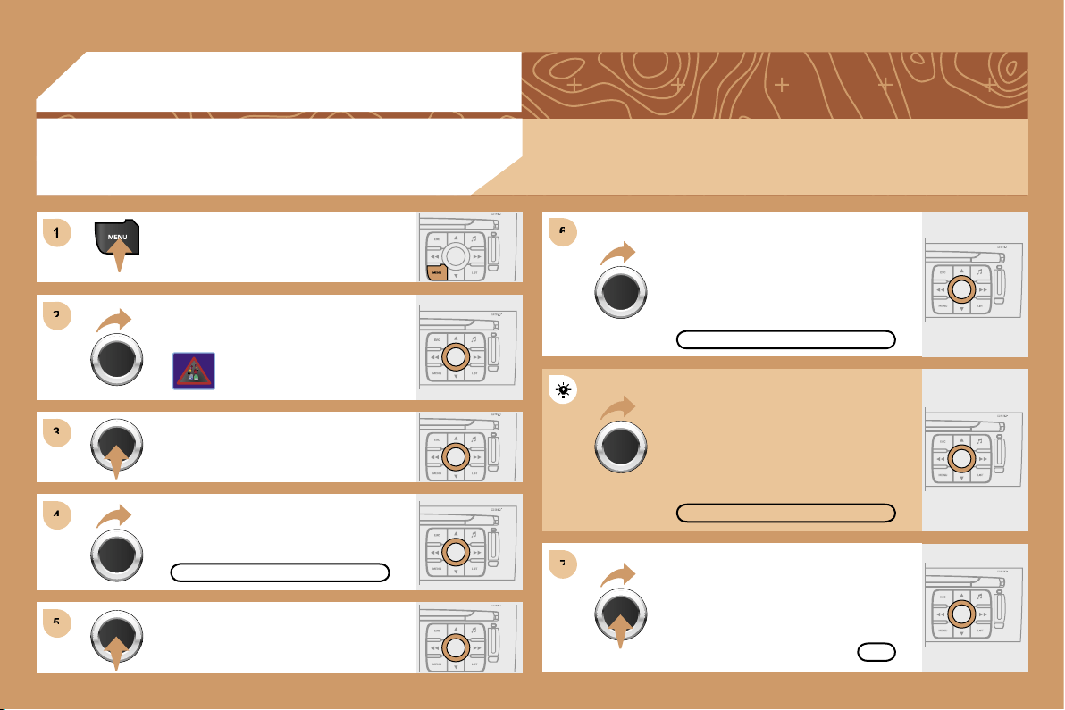
183
1
1
2
2
3
3
4
4
6
6
5
5
7
7
04
Press the MENU button.
READ MESSAGES
NEW MESSAGE DISPLAY
OK
CONFIGURING THE TMC MESSAGE
ANNOUNCEMENTS
We recommend that you do not tick the NEW MESSAGE DISPLAY tab for regions with heavy traffic.
Turn the dial and select the TRAFFIC
INFORMATION function.
Press the dial to confirm the selection.
Press the dial to confirm the selection.
Turn the dial and select the
CONFIGURE MESSAGE
ANNOUNCEMENT function.
Select the READ MESSAGES tab.
The Traffic Information Messages will
be read by the voice synthesiser.
Select the NEW MESSAGE DISPLAY
tab.
The traffic information messages
are extended to the filters selected
(geographic...) and can also be
displayed when guidance is not
active.
TRAFFIC INFORMATION
Select OK and press the dial to
confirm.
CONFIGURE MESSAGE ANNOUNCEMENT
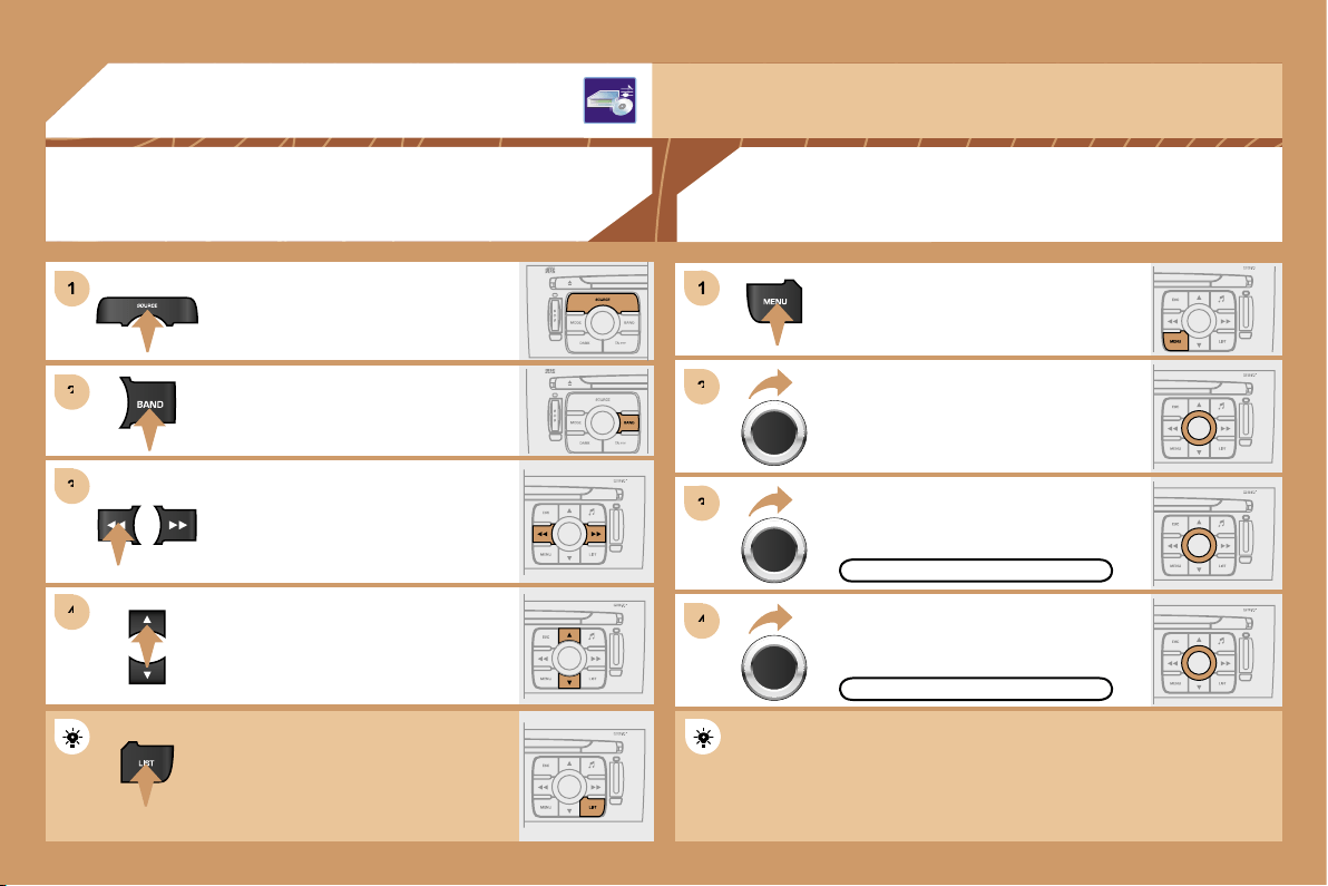
184
1
1
2
2
3
3
4
4
1
1
2
2
3
3
4
4
05
AUDIO/VIDEO
RADIO
SELECTING A STATION
Press the SOURCE button several
times in succession and select the
RADIO.
Press the BAND button to select a
waveband: FM1, FM2, FMast, AM.
Briefly press one of the buttons to
carry out an automatic search of the
radio stations.
Press one of the buttons to carry out a
manual search of the radio stations.
Press the LIST button to display
the list of stations received locally
(60 maximum).
To update this list, press for more than
two seconds.
The external environment (hills, buildings, tunnels, basement car parks, ...) may block reception,
including in RDS mode. This is a normal effect of the way in which radio waves are transmitted and
does not indicate any failure of the audio equipment.
RDS
Select ACTIVATE FREQUENCY
FOLLOWING (RDS) then press OK.
RDS appears on the display.
Select the RADIO PREFERENCES
function then press OK.
Select AUDIO FUNCTIONS then
press OK.
Press the MENU button.
The RDS, if displayed, enables you to continue listening to the
same station by means of frequency following. However, in certain
conditions, this RDS station is not followed throughout the country
as radio stations do not cover 100 % of the territory. This explains
the loss of reception of the station during a journey.
ACTIVATE FREQUENCY FOLLOWING (RDS)
RADIO PREFERENCES
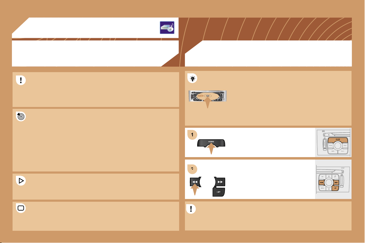
185
1
1
2
2
05
AUDIO/VIDEO
MP3 CD
INFORMATION AND ADVICE
The MP3 format, an abbreviation of MPEG 1.2 & 2.5 Audio Layer 3,
is an audio compression standard which permits the recording of
several tens of music files on a single disc.
In order to be able to play a recorded CDR or CDRW, when
recording it is preferable to select standards ISO 9660 level 1.2 or
Joliet.
If the disc is recorded in another format, it may not be played
correctly.
It is recommended that the same recording standard is always used
for an individual disc, with as low a speed as possible
(4x maximum) for optimum sound quality.
In the particular case of a multi-session CD, the Joliet standard is
recommended.
The audio equipment will only play audio files with the extension
".mp3" with a sampling rate of 22.05 KHz or 44.1 KHz. No other
type of file (.wma, .mp4, m3u...) can be played.
It is advisable to restrict file names to 20 characters without using
special characters (e.g.: " " ? ; ù) to avoid any playing or displaying
problems.
CD
PLAYING A CD OR AN MP3 COMPILATION
Insert circular compact discs only. Some anti-pirating
systems, on original discs or CDs copied using
a personal recorder, may generate malfunctions
regardless of the quality of the original player.
Insert an audio CD or an MP3 compilation in the player,
play begins automatically.
If the player already contains a disc,
press the SOURCE button several
times in succession and select CD to
listen to it.
Press one of the buttons to select a
track on the CD.
Press the LIST button to display
the list of tracks on the CD or of the
directories of the MP3 compilation.
The playing and displaying of an MP3 compilation may depend on
the recording programme and/or the parameter settings used. We
recommend use of the ISO 9660 recording standard.
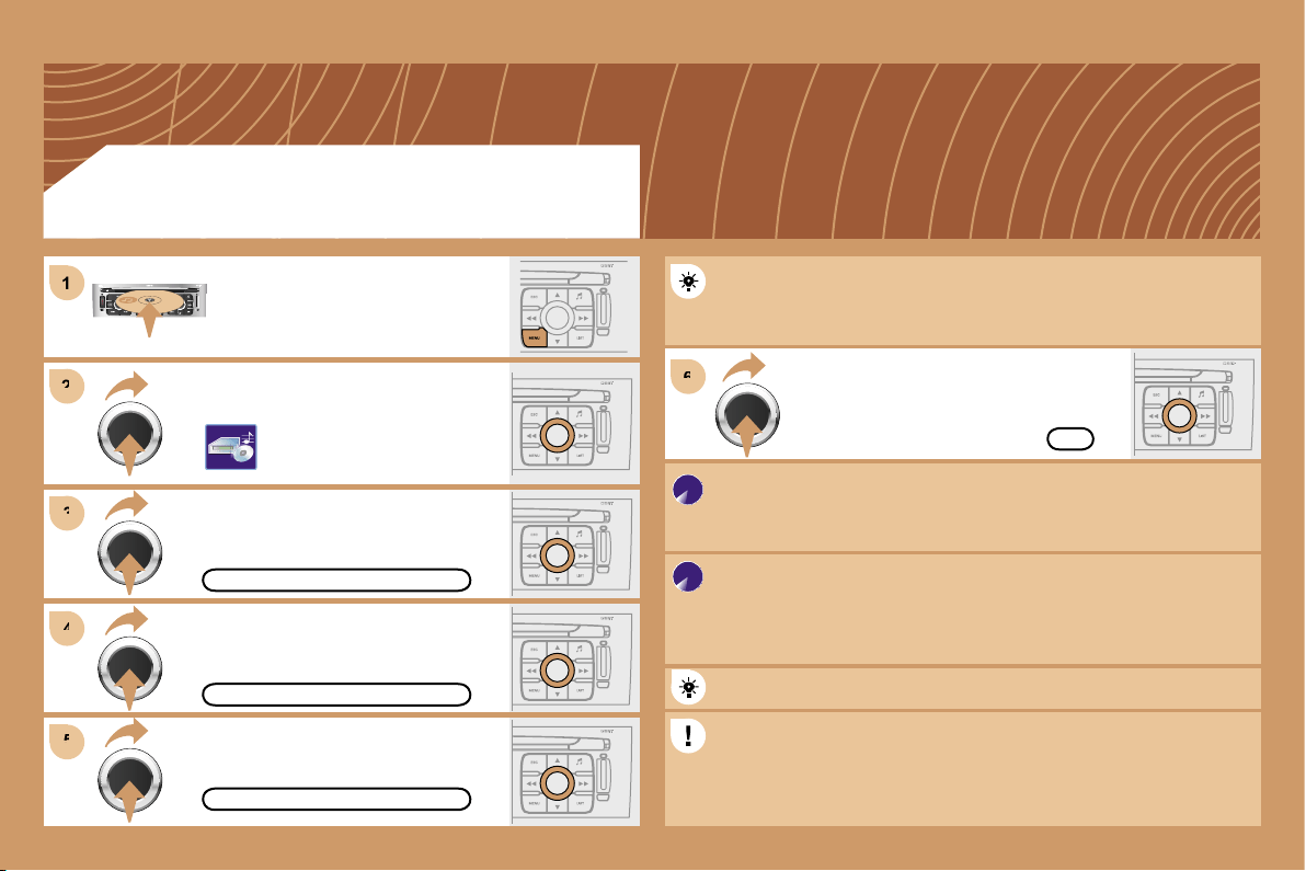
186
2
2
3
3
6
6
4
4
5
5
1
1
OK
CREATE ALBUM
COMPLETE CD
COPY CD TO JUKEBOX
Select COPY CD TO JUKEBOX and
press the dial to confirm.
Select COMPLETE CD to copy
the entire CD and press the dial to
confirm.
Select CREATE ALBUM and press
the dial to confirm.
The AUTO CREATION tab automatically copies the CD by default
into an album of the type "album n°...".
The audio or MP3 CD is copied onto the hard disc. Copying may
take approximately 20 minutes depending on the duration of the CD.
During this copying phase, it is not possible to listen to the albums
previously recorded on the hard disc or the CDs.
Select the letters one by one and select
OK to confirm.
If it is not an MP3 CD, the Jukebox automatically compresses
the CD in MP3 format. The compression may take approximately
20 minutes depending on the duration of the CD. During this
compression phase, it is possible to listen to the CD or to albums
previously recorded on the hard disc.
A long press on the SOURCE button starts the copying of the CD.
When copying an MP3 CD, the Jukebox only retains the last album
level. It is not possible to copy files from the Jukebox to a CD.
The STOP THE CD COPY action does not delete the files which
have already been transferred onto the jukebox hard disc.
Select AUDIO FUNCTIONS and press
the dial to confirm.
Insert a CD or an MP3 compilation
and press the MENU button.
JUKEBOX FUNCTION
COPYING A CD ONTO THE HARD DISC
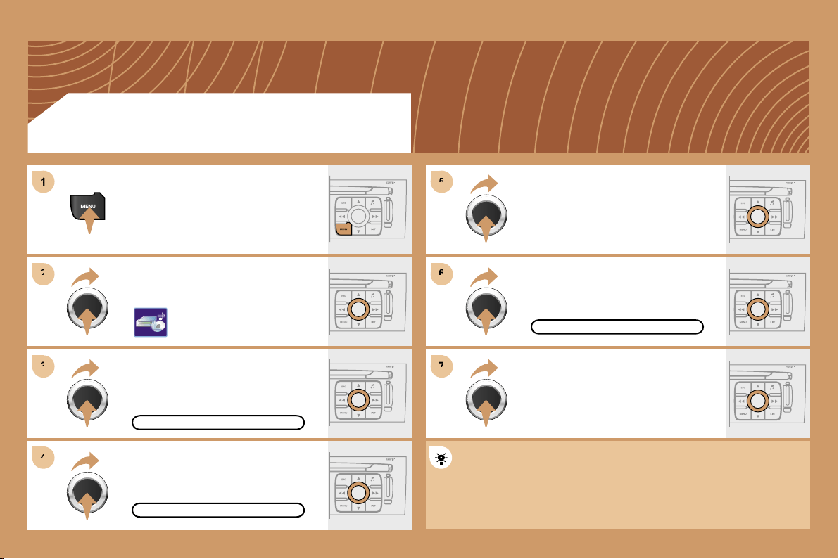
187
6
6
7
7
5
5
2
2
3
3
4
4
1
1
RENAME
JUKEBOX
JUKEBOX MANAGEMENT
JUKEBOX FUNCTION
RENAMING AN ALBUM
Press the MENU button.
Select AUDIO FUNCTIONS and
press the dial to confirm.
Select the JUKEBOX function and
press the dial to confirm.
Select the JUKEBOX MANAGEMENT
function and press the dial to confirm.
Select the album to be renamed and
press the dial to confirm.
Select the RENAME tab and press the
dial to confirm.
Turn the dial and select the letters of
the album title one by one confirming
each time by pressing the dial.
Use the alphanumeric keypad to enter the letters of the album title
one by one.
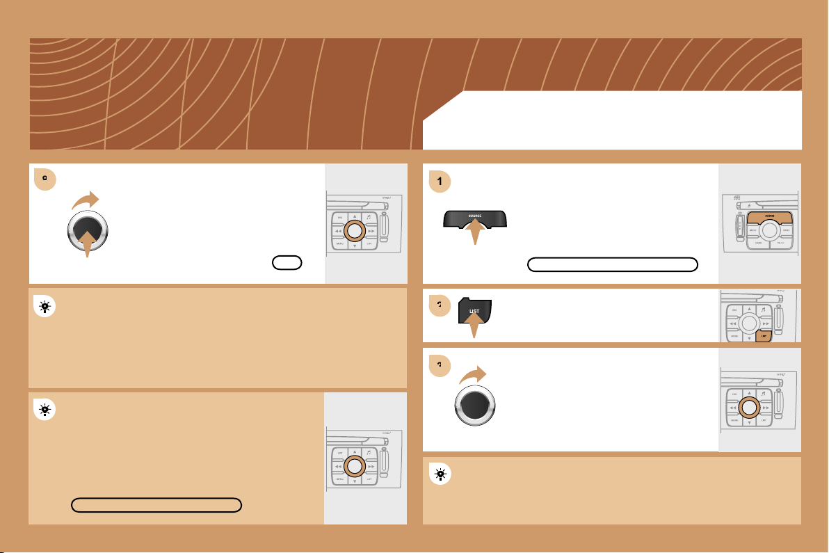
188
8
8
1
1
2
2
3
3
DELETE
OK
JUKEBOX FUNCTION
LISTENING TO THE JUKEBOX
Press the SOURCE button several
times in succession and select the
JUKEBOX function.
Press the LIST button.
Turn the dial to select the files.
Press the ESC button to return to the first file level.
JUKEBOX
Select OK and press the dial to
confirm.
To rename the tracks of an album, follow the same procedure,
selecting the tracks to be renamed.
Use the ESC button to exit from the list of tracks.
Select the DELETE function to delete an album or a
track from the Jukebox.
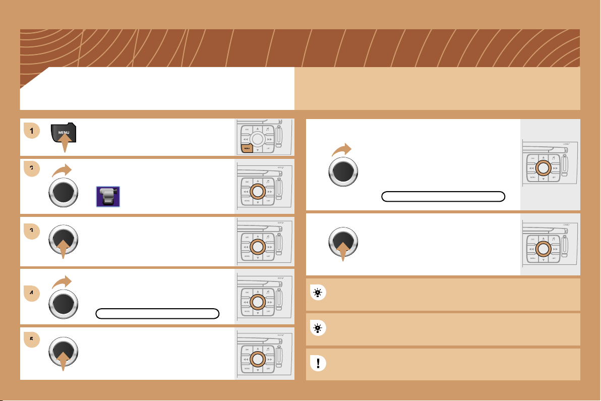
189
1
1
2
2
3
3
4
4
5
5
You can connect video equipment (camcorder, digital camera, DVD player...) to the three audio/video
sockets, located in the glove box.
Turn the dial and select the VIDEO
function.
After connecting the video equipment,
press the MENU button.
Turn the dial and select the
ACTIVATE VIDEO MODE function to
activate/deactivate the video.
Press the dial to confirm the selection.
ACTIVATE VIDEO MODE
Press the dial to confirm the selection.
Pressing the "SOURCE" button several times in succession permits
the selection of an audio source other than that of the video.
Pressing the "MODE" or "DARK" button disconnects the displaying
of the video.
Turn the dial and select the VIDEO
PARAMETERS function to set the
display format, the brightness, the
contrast and the colours.
VIDEO PARAMETERS
Press the dial to confirm the selection.
VIDEO MENU
Videos can only be displayed when stationary.
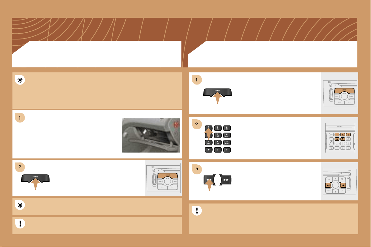
190
1
1
2
2
1
1
3
3
2
2
Press the MENU button then select the CONFIGURATION function,
then SOUNDS, then ACTIVATE AUXILIARY SOURCE to activate
the auxiliary input of the RT4 GPS audio/telephone.
Connect the portable equipment (MP3
player…) to the audio sockets (white and
red, RCA type) located in the glove box
using a JACK/RCA audio cable.
Press the SOURCE button several
times in succession and select AUX.
CD CHANGER
PLAYING A CD (NOT MP3 COMPATIBLE)
Insert one or more CDs in the
changer.
Press the SOURCE button several
times in succession and select CD
CHANGER.
Press one of the buttons on the
alphanumeric keypad to select the
corresponding CD.
Press one of the buttons to select a
track on the CD.
The displaying and management of the commands takes place via
the portable equipment.
It is not possible to copy the files onto the hard disc from the auxiliary
input.
It is not possible to copy the files onto the hard disc from the CD
changer.
USING THE AUXILIARY INPUT (AUX)
JACK/RCA AUDIO CABLE NOT SUPPLIED
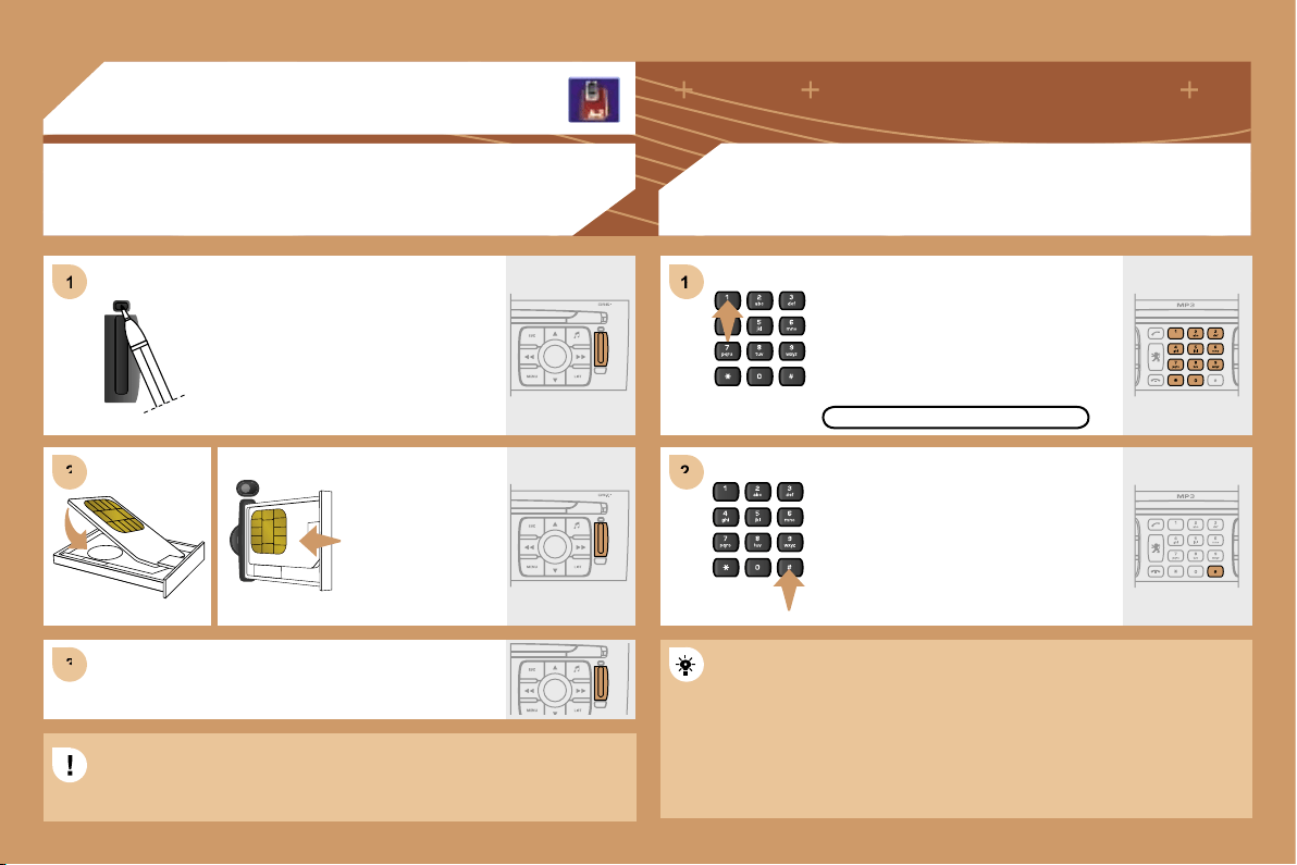
191
1
2
2
3
3
1
1
2
2
06
INSTALLING YOUR SIM CARD
(NOT SUPPLIED)
ENTERING THE PIN CODE
Access the slot by pressing the button
using the tip of a pen.
Install the SIM card
in the holder and
then insert it in the
slot.
To remove the SIM card, repeat step 1.
Your SIM card must be installed and removed with the RT4 GPS
audio/telephone switched off and the ignition off.
Enter the PIN code on the keypad.
Confirm the PIN code by pressing
button #.
PIN
CODE
When entering your PIN code, tick the STORE PIN tab to gain
access to the telephone without having to enter this code when it is
used subsequently.
TELEPHONE
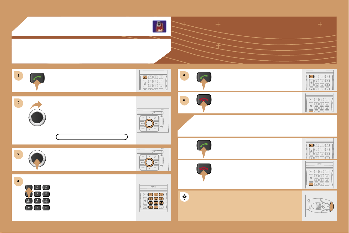
192
1
1
2
2
3
3
4
4
5
5
6
6
06
TELEPHONE
CALLING A CONTACT
Turn the dial and select the DIAL
function.
Press the PICK UP button to display
the superimposed telephone menu.
Press the dial to confirm the selection.
Dial the telephone number of your
contact using the alphanumeric
keypad.
Press the PICK UP button to call the
number dialled.
Press the HANG UP button to end
the call.
ACCEPTING OR REFUSING A CALL
Press the PICK UP button to accept
a call.
Press the HANG UP button to refuse
a call.
DIAL
Press the end of the steering wheel stalk for more
than 2 seconds to access the telephone menu:
calls log, directory, voice mailbox.
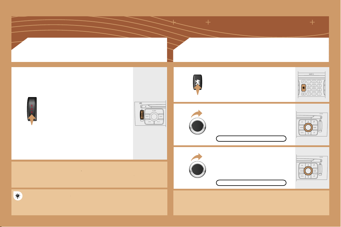
193
EMERGENCY CALL
* On condition that the
PEUGEOT
Emergency contract has been signed.
PEUGEOT
PEUGEOT
This is free and of unlimited duration. Contact a
PEUGEOT
dealer.
PEUGEOT
PEUGEOT
In an emergency, press the SOS
button until an audible signal is
heard and a CONFIRMATION/
CANCELLATION screen is displayed
(if valid SIM card inserted).
A call is made to the emergency
services (112).
In certain countries*, this emergency
call is made directly by the
PEUGEOT
Emergency team which locates the
vehicle and alerts the appropriate
emergency services as quickly as
possible.
PEUGEOT ASSISTANCE
CUSTOMER CONTACT CENTRE
When the
PEUGEOT
Emergency contract has been signed, it
PEUGEOT
PEUGEOT
is recommended that an initial call is made to the
PEUGEOT
Emergency team.
CONSULTING THE SERVICES
Press the LION button to gain access
to the
PEUGEOT
services*.
PEUGEOT
PEUGEOT
Select CUSTOMER CONTACT
CENTRE to request any information
about the
PEUGEOT
marque.
PEUGEOT
PEUGEOT
Select PEUGEOT ASSISTANCE to
make a breakdown assistance call.
* These services and options are subject to conditions and availability.
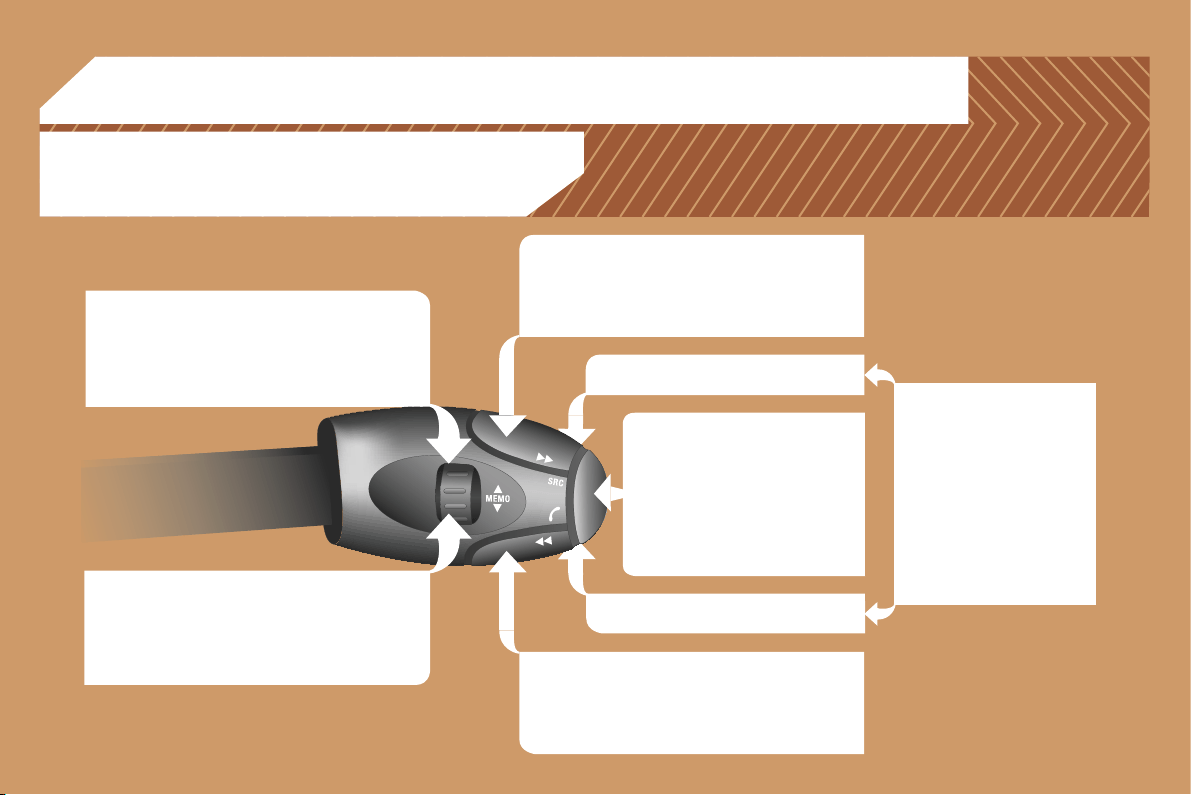
194
07
RADIO: selection of the previous stored station.
MP3/JUKEBOX: selection of the previous directory.
CD CHANGER: selection of the previous CD.
Selection of the previous item on a menu.
RADIO: selection of the next stored station.
MP3/JUKEBOX: selection of the next directory.
CD CHANGER: selection of the next CD.
Selection of the next item on a menu.
RADIO: automatic search for a higher frequency.
CD/MP3/JUKEBOX/CD CHANGER: selection of the
next track.
CD/CD CHANGER: continuous press: fast forwards
play.
RADIO: automatic search for a lower frequency.
CD/MP3/JUKEBOX/CD CHANGER: selection of the
previous track.
CD/CD CHANGER: continuous press: fast backwards
play.
- Change of sound source.
- Confirmation of a selection.
- Pick up/Hang up the telephone.
- Press for more than 2 seconds:
access to the telephone menu.
Volume increase.
Volume decrease.
CONTROL SHORT-CUTS
STEERING WHEEL CONTROLS
Mute: by pressing the volume
increase and decrease
buttons simultaneously.
The sound is restored by
pressing one of the two
volume buttons.
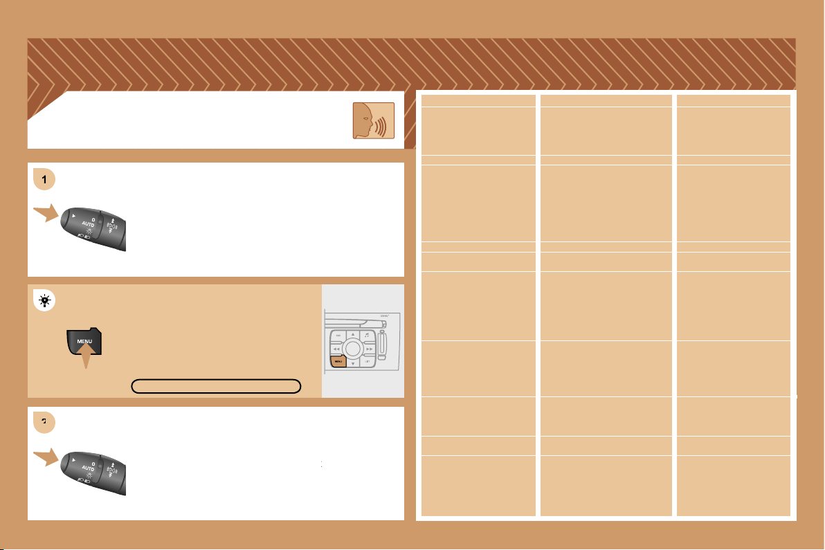
195
2
2
1
1
Press the end of the lights stalk to start the voice
Press the end of the lights stalk to start the voice
recognition.
Say the words one by one and wait for the audible
Say the words one by one and wait for the audible
confirmation signal between each word.
The list which follows is exhaustive.
VOICE COMMANDS
DISPLAYING THE LIST AND USING THEM
To display the list of available voice commands, press
To display the list of available voice commands, press
the end of the lights stalk to start the voice recognition,
the end of the lights stalk to start the voice recognition,
then say HELP or WHAT CAN I SAY.
For the same operation, press and
hold the MENU button and select the
function VOICE COMMANDS LIST.
VOICE COMMANDS LIST
LEVEL 1
display
call
changer
guide to
traffic info
CD player/jukebox
navigation
radio
SMS/message
telephone
LEVEL 2
audio
guidance
navigation
trip computer
telephone
description
disc number
previous/next disc
random play
list
track number
previous/next track
repeat
scan
description
display
read
random play
list
track number
previous/next track
directory (MP3 CD)
scan
stop/resume
directory
show
zoom out/in
autostore
list
memory
previous/next
display
read
voice mailbox
last number
voice message service
directory
LEVEL 3
1 … 20
1 ... 20
previous/next
repeat
destination
description
vehicle
1 … 6
description
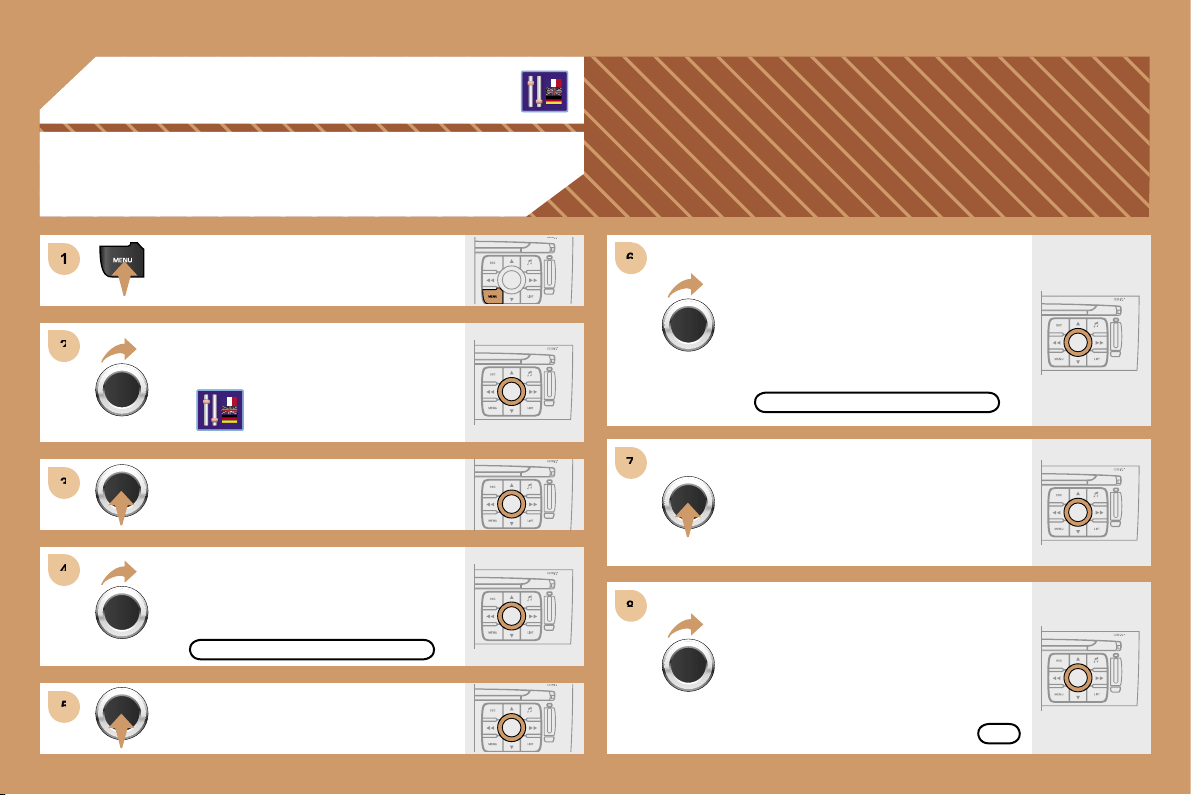
196
1
1
2
2
3
3
4
4
5
5
6
6
7
7
8
8
08
CONFIGURATION
ADJUSTING THE DATE AND TIME
Press the MENU button.
Turn the dial and select the
CONFIGURATION function.
Press the dial to confirm the selection.
Turn the dial and select the DISPLAY
CONFIGURATION function.
Adjust the parameters one by one
confirming by pressing the dial. Next
select the OK tab on the display then
confirm.
Press the dial to confirm the selection.
DISPLAY CONFIGURATION
ADJUST THE DATE AND TIME
OK
Press the dial to confirm the selection.
Turn the dial and select the ADJUST
THE DATE AND TIME function.
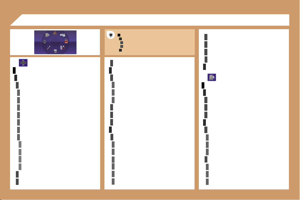
197
1
2
3
3
2
1
4
4
2
3
4
3
1
2
3
3
3
4
4
4
4
4
4
4
5
5
5
5
3
4
4
4
3
3
3
2
3
4
4
4
4
4
4
2
2
3
3
3
3
3
2
3
3
3
4
4
4
09
MAIN FUNCTION
CHOICE A
choice A1
choice A2
CHOICE B...
NAVIGATION - GUIDANCE
SELECT DESTINATION
enter an address
country:
town:
road:
N°/_:
curr. loc
Archive
POI
near
on the route
around current place
search by name
GPS coordinates
directory
previous destinations
JOURNEY LEGS AND ROUTE
add a stage
enter an address
directory
previous destinations
order/delete journey legs
divert route
chosen destination
GUIDANCE OPTIONS
define calculation criteria
fastest
shortest
distance/time
with tolls
with ferry
traffic info
DISPLAY FLOW CHARTS
set speech synthesis
activate/deactivate road names
map data base description
delete last destinations
STOP/RESUME GUIDANCE
MAP
MAP ORIENTATION
vehicle direction
north direction
3D view
MAP DETAILS
administration and safety
town halls, town centre
universities, colleges
hospitals
hotels, restaurants and shops
hotels
restaurants
vinyards
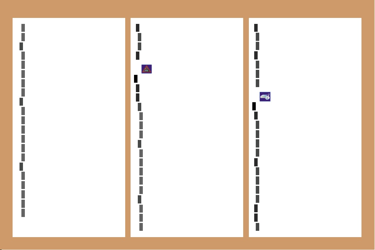
198
4
4
4
4
4
4
4
4
3
4
4
4
4
3
3
4
4
1
2
3
4
4
4
3
4
4
4
4
4
1
2
3
3
3
3
3
3
3
3
2
3
2
2
3
3
3
3
2
2
4
4
2
4
4
3
3
4
4
4
3
3
2 2
business centres
supermarkets, shopping
culture, tourism and shows
tourism
culture and museums
casinos and nightlife
cinemas and theatres
shows and exhibitions
sports and open air centres
sports centres
golf courses
skating rinks, bowling alleys
winter sports resorts
parks, gardens
theme parks
transport and automobile
airports, ports
stations, bus stations
vehicle rental
lay-bys, car parks
service stations, garages
DISPLAY MAP
full screen map
map in window
MOVE THE MAP
CONFIGURE MESSAGE ANNOUNCEMENT
read messages
new message display
SELECT TMC STATION
AUTOMATIC TMC
manual TMC
list of TMC stations
TRAFFIC INFORMATION
READ MESSAGES
FILTER TRAFFIC INFORMATION
geographic filter
around the vehicle
around location
on the route
road information
traffic information
road closure
size limit
road condition
weather and visibility
urban/city information
parking
public transport
demonstrations
AUDIO FUNCTIONS
RADIO FAVOURITES
enter a frequency
activate/deactivate RDS mode
activate/deactivate regional mode
display/hide radio text
CD, JUKEBOX FAVOURITES
activate/deactivate Introscan (SCN)
activate/deactivate Random mode (RDM)
activate/deactivate Repeat (RPT)
activate/deactivate display of CD info
STOP THE COPY
COPY CD TO JUKEBOX
copy complete
CD
199
4
3
4
5
5
5
5
4
4
4
3
4
3
4
4
3
3
3
3
2
5
5
1
2
3
4
3
3
3
3
3
2
3
3
3
2
4
4
2
4
3
4
4
4
3
4
4
3
3
4
4
4
4
4
4
5
5
5
5
2
3
5
5
5
3
TELEMATICS
CALL
call list
dial
directory
mailbox
services
customer contact centre
PEUGEOT
assistance
PEUGEOT
PEUGEOT
messages received
multiple selection
current album
current track
JUKEBOX
jukebox management
jukebox configuration
hi-fi (320 kbps)
high (192 kbps)
normal (128 kbps)
delete jukebox data
PLAYLIST MANAGEMENT
send a text message
write a text message
delete list of text messages
TELEPHONE FUNCTIONS
network
network search mode
automatic mode
manual mode
networks available
length of calls
zero reset
manage PIN code
activate/deactivate
save PIN number
modify PIN code
call options
configure calls
display my number
automatic reply after x ring(s)
ring options
for voice calls
for text messages (SMS)
DIRECTORY
managing directory files
consult or modify a file
add a file
delete a file
delete all files
configure directory
select a directory
name directory
select starting directory
file transfer
exchange by infrared
send all records
send one record
receive by infrared
exchange with SIM card
send all records to SIM
send one record to SIM
receive all SIM files
receive a SIM file
TEXT MESSAGES (SMS)
read received text messages
200
1
2
3
3
3
3
2
3
3
4
4
1
3
2
3
1
2
3
3
2
2
2
1
2
2
2
1
1
4
3
2
2
3
3
6
1
Flow chart version 7.0
text message ring
call diversion to mailbox n°
delete calls log
* The parameters vary according to vehicle
(refer to the "Multifunction displays" chapter).
CONFIGURATION
DISPLAY CONFIGURATION
choose colour
adjust luminosity
set date and time
select units
SOUND
voice commands setting
speech synthesis setting
guidance instructions volume
other message volume
select female/male voice
activate/deactivate auxiliary source
SELECT LANGUAGE
DEFINE VEHICLE PARAMETERS*
VIDEO
ACTIVATE VIDEO MODE
VIDEO PARAMETERS
D
isplay formats
adjust luminosity
set colours
set contrasts
VEHICLE DIAGNOSTICS
ALERT LOG
STATUS OF FUNCTIONS*
RESET TYRE PRESS. DETEC. SYS.*
Press the MENU button for more
than 2 seconds
to access the
following flow chart.
VOICE COMMANDS LIST
AUDIO/TELEPHONE DIAGNOSTICS
GPS COVERAGE
UNIT BACKUP POWER
UNIT DESCRIPTION
NAVIGATION DEMONSTRATION
SERVICES CONFIGURATION
Press the Music button several
times in
succession to access the
following settings.
MUSICAL AMBIENCE
BASS
TREBLE
LOUDNESS CORRECTION
FR-RR BALANCE
LH-RH BALANCE
AUTO VOLUME CORRECTION
Each audio source (Radio, CD, MP3,
Jukebox, CD changer) has its own
separate settings.
213
QUESTION
SOLUTION
RESPONSE
There is a difference in
sound quality between
the different audio
sources (radio, CD, CD
changer...).
Check that the audio settings (Volume, Bass,
Treble, Ambience, Loudness) are adapted to
the sources listened to. It is advisable to set
the AUDIO functions (Bass, Treble, Front-Rear
Balance, Left-Right Balance) to the middle
position, select the musical ambience "None"
and set the loudness correction to the "Active"
position in CD mode or to the "Inactive" position
in radio mode.
For optimum sound quality, the audio settings (Volume, Bass, Treble,
Ambience, Loudness) can be adapted to the different sound sources,
which may result in audible differences when changing source (radio,
CD, CD changer...).
The CD is ejected
automatically or is not
played by the player.
- Check that the CD is inserted in the player the
right way up.
- Check the condition of the CD: the CD cannot
be played if it is too damaged.
- Check the content in the case of a recorded
CD: consult the advice in the Audio section.
- The audio equipment’s CD player does not
play DVDs.
- Due to inadequate quality, certain recorded
CDs will not be played by the audio system.
- The CD changer does not play MP3 CDs.
The CD is inserted upside down, is unplayable, does not contain any
audio data or contains an audio format which the player cannot play.
The CD is protected by an anti-pirating protection system which is not
recognised by the audio equipment.
FREQUENTLY ASKED QUESTIONS
The CD player sound
is poor.
The CD used is scratched or of poor quality.
Insert good quality CDs and store them in
suitable conditions.
The audio equipment settings (bass, treble, ambiences) are unsuitable.
Set the treble or bass level to 0, without
selecting an ambience.

214
QUESTION
SOLUTION
RESPONSE
The stored stations
do not function (no
sound, 87.5 Mhz is
displayed...).
An incorrect waveband is selected.
Press the BAND AST button to return to the
waveband (AM, FM1, FM2, FMAST) on which the
stations are stored.
The traffic announcement
(TA) is displayed. I do
not receive any traffic
information.
Tune to a radio station which broadcasts traffic
information.
The radio station is not part of the regional traffic information network.
The quality of reception
of the radio station
listened to gradually
deteriorates or the
stored stations do
not function (no
sound, 87.5 Mhz is
displayed...).
The vehicle is too far from the transmitter used by the station listened to or
there is no transmitter in the geographical area through which the vehicle
is travelling.
The environment (hills, buildings, tunnels, basement car parks...) block
reception, including in RDS mode.
The aerial is absent or has been damaged (for example when going
through a car wash or into an underground car park).
Activate the RDS function to enable the system
to check whether there is a more powerful
transmitter in the geographical area.
This phenomenon is normal and does not
indicate a failure of the audio equipment.
Have the aerial checked by a
PEUGEOT
dealer.
PEUGEOT
PEUGEOT
Sound cut-outs of 1
to 2 seconds in radio
mode.
During this brief sound cut-out, the RDS searches for any frequency
permitting better reception of the station.
Deactivate the RDS function if the phenomenon
is too frequent and always on the same route.
With the engine off,
the audio equipment
switches off after a few
minutes of use.
When the engine is switched off, the audio equipment operating time
depends on the battery charge.
The switch-off is normal: the audio equipment switches to economy mode
and switches off to prevent discharging of the vehicle’s battery.
Start the vehicle’s engine to increase the battery
charge.
The message "the audio
system is overheated"
appears on the display.
Switch the audio system off for a few minutes to
allow the system to cool.
In order to protect the installation if the surrounding temperature is too
high, the audio equipment switches to an automatic thermal protection
mode leading to a reduction of the volume or stopping of the playing of the
CD.

215
QUESTION
SOLUTION
RESPONSE
The TRAFFIC INFO
box is ticked. However,
certain traffic jams
along the route are not
indicated in real time.
On starting, it is several minutes before the system begins to receive the
traffic information.
Wait until the traffic information is being received
correctly (displaying of the traffic information
symbols on the map).
In certain countries, only major routes (motorways, ...) are listed for the
traffic information.
The time taken to
calculate a route
sometimes seems
longer than usual.
longer than usual.
This phenomenon is normal. The system is
dependent on the traffic information available.
The performance of the system may slow down temporarily if a CD is
being copied onto the Jukebox at the same time as a route is being
calculated.
Wait until the CD has been copied or stop the
copying before starting the guidance function.
Does the emergency
call function work
without a SIM card?
No, European regulations impose the presence of a SIM card in order to
make an emergency call.
Insert a valid SIM card in the slot on the RT4
GPS audio/telephone.
My SIM card is not
recognised.
The RT4 accepts 3.3 V SIM cards, the old 5 V and 1.8 V SIM cards are
not recognised.
Contact your telephone operator.
After changing a wheel,
the system loses its
location.
The RT4 GPS audio/telephone uses the wheel rotation information to
improve the GPS locating function. If a wheel is changed or deflates
suddenly, the system recalculates the location. For approximately
ten minutes, this recalculation may affect the quality of the locating function.
Wait until the system has completed its
recalculation.
The table below groups together the answers to the most frequently asked questions concerning the RT4 audio/telephone.
The location on the
map is incorrect or
inaccurate.
The altitude is not
displayed.
On starting, the initialisation of the GPS may take up to 3 minutes to
receive more than 3 satellites correctly.
Wait until the system has started up completely.
Check that there is a GPS coverage of at
least 3 satellites (long press on the MENU
button, then select AUDIO/TELEPHONE
DIAGNOSTICS, then GPS COVERAGE).
Depending on the geographical environment (tunnel, ...) or the weather,
the conditions of reception of the GPS signal may vary.
This phenomenon is normal. The system is
dependent on the conditions of reception of the
GPS signal.
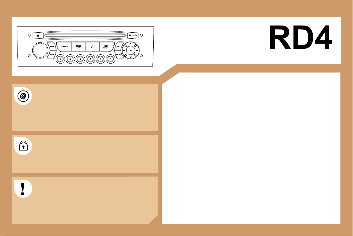
201
AUDIO EQUIPMENT/HANDS-FREE KIT
CONTENTS
• 01 First steps pg. 202
• 02 General menu pg. 203
• 03 Audio pg. 204
• 04 Hands-free kit pg. 208
• 05 Control short-cuts pg. 209
• 06 Configuration pg. 210
• 07 Display flow charts pg. 211
• Frequently asked questions pg. 213
Information on the functions offered by this equipment can
be found on the site: http://public.servicebox.peugeot.com
- access is free. From your vehicle’s interactive telematic
guide, make your selection, process, follow the actions
step by step, print.
The RD4 audio equipment is coded in such a way that
it will only operate in your vehicle. If it is to be installed
in another vehicle, contact your PEUGEOT dealer for
configuration of the system.
For safety reasons, the driver must carry out operations
which require prolonged attention while the vehicle is
stationary.
When the engine is switched off and to prevent
discharging of the battery, the RD4 audio system may
switch off after a few minutes.
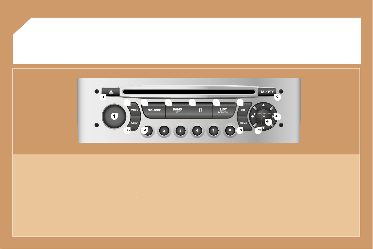
202
1
1
2
2
10
10
11
11
13
13
14
14
15
15
3
3
4
4
5
5
6
6
7
7
8
8
9
9
12
12
01
FIRST STEPS
1 -
On/Off and volume adjustment.
1 -
1 -
2 -
CD eject.
2 -
2 -
3 -
Selection of the screen display mode.
3 -
3 -
4 -
Selection of the source: radio, CD and CD changer.
4 -
4 -
5 -
Selection of the FM1, FM2, FMast and AM wavebands.
5 -
5 -
6 -
Setting the audio options:
6 -
6 -
front/rear balance, left/right balance, loudness, sound
ambiences.
7 -
Displaying of the list of local stations, of the tracks on the CD
7 -
7 -
or of the MP3 directories.
8 -
Abandon current operation.
8 -
8 -
9 -
TA (Traffic Announcement) function on/off.
9 -
9 -
Long press: access to the PTY (TYpes of radio Programme)
mode.
10 -
Confirmation.
10 -
10 -
11 -
Automatic search for a lower/higher frequency.
11 -
11 -
Selection of previous/next CD or MP3 track.
12 -
Selection of a lower/higher radio frequency.
12 -
12 -
Selection of the previous/next CD.
Selection of the previous/next MP3 directory.
13 -
Displaying of the general menu.
13 -
13 -
14 -
Buttons 1 to 6:
14 -
14 -
Selection of a stored radio station.
Selection of a CD in the CD changer.
Long press: storing of a station.
15 -
The DARK button changes the display on the screen to
15 -
15 -
improve driving comfort at night.
1st press: lighting of the top banner only.
2nd press: black screen display.
3rd press: return to the standard display.
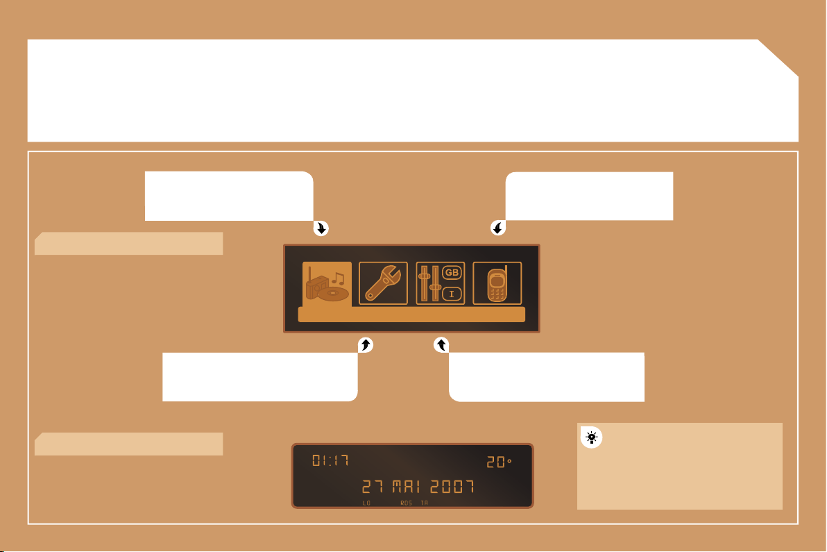
203
02
GENERAL MENU
AUDIO FUNCTIONS: radio, CD,
options.
VEHICLE DIAGNOSTICS: warnings.
TELEPHONE: hands-free kit,
matching, management of a
communication.
PERSONALISATION-CONFIGURATION:
vehicle parameters, display, languages.
> MONOCHROME DISPLAY C
> MONOCHROME DISPLAY A
For a detailed global view of the
menus available, refer to the
"Display flow charts" section of
this RD4 chapter.
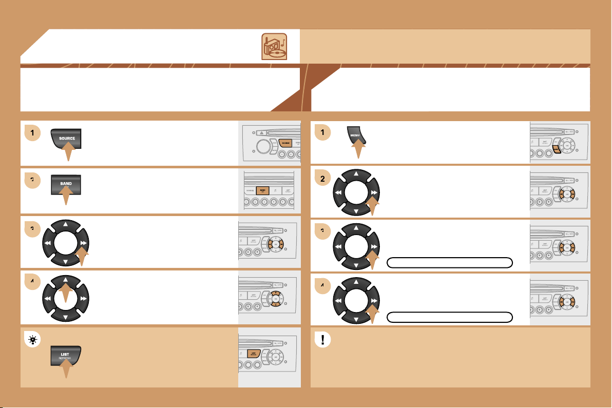
204
1
1
2
2
3
3
4
4
2
4
4
3
3
1
1
03
AUDIO
RADIO
SELECTING A STATION
Press the SOURCE button several
times in succession and select the
radio.
Press the BAND AST button to select
a waveband: FM1, FM2, FMast, AM.
Briefly press one of the buttons to
carry out an automatic search of the
radio stations.
Press one of the buttons to carry out a
manual search of the radio stations.
Press the LIST REFRESH button to
display the list of stations received
locally (30 stations maximum).
To update this list, press for more than
two seconds.
Select ACTIVATE FREQUENCY
FOLLOWING (RDS) then press OK.
RDS appears on the display.
Select the FM WAVEBAND
PREFERENCES function then press
OK.
Select AUDIO FUNCTIONS then
press OK.
Press the MENU button.
ACTIVATE FREQUENCY FOLLOWING (RDS)
FM WAVEBAND PREFERENCES
The external environment (hills, buildings, tunnels, basement car parks) may block reception, including
in RDS mode. This is a normal effect of the way in which radio waves are transmitted and does not
indicate any failure of the audio equipment.
RDS
The RDS, if displayed, enables you to continue listening to the
same station by means of frequency following. However, in certain
conditions, this RDS station is not followed throughout the country
as radio stations do not cover 100 % of the territory. This explains
the loss of reception of the station during a journey.
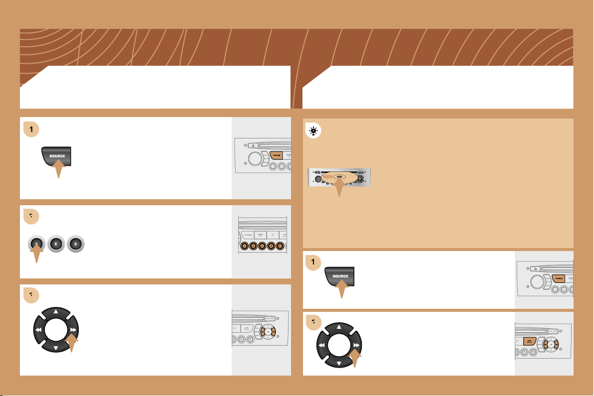
205
1
1
2
2
3
3
1
2
2
CD CHANGER
PLAYING A CD (NOT MP3 COMPATIBLE)
Insert the CDs in the changer one by
one.
Press the SOURCE button several
times in succession and select CD
CHANGER.
Press one of the buttons on the
numeric keypad to select the
corresponding CD.
Press one of the buttons to select a
track on the CD.
Press and hold one of the buttons for
fast forwards or backwards play.
Insert circular compact discs only.
Some anti-pirating systems, on original discs or CDs
copied using a personal recorder, may cause faults
which are no reflection on the quality of the original
player.
Without pressing the EJECT button, insert a CD in the
player, play begins automatically.
To play a disc which has already been
inserted, press the SOURCE button
several times in succession and select
CD.
Press one of the buttons to select a
track on the CD.
Press the LIST REFRESH button to
display the list of tracks on the CD.
CD
PLAYING A CD
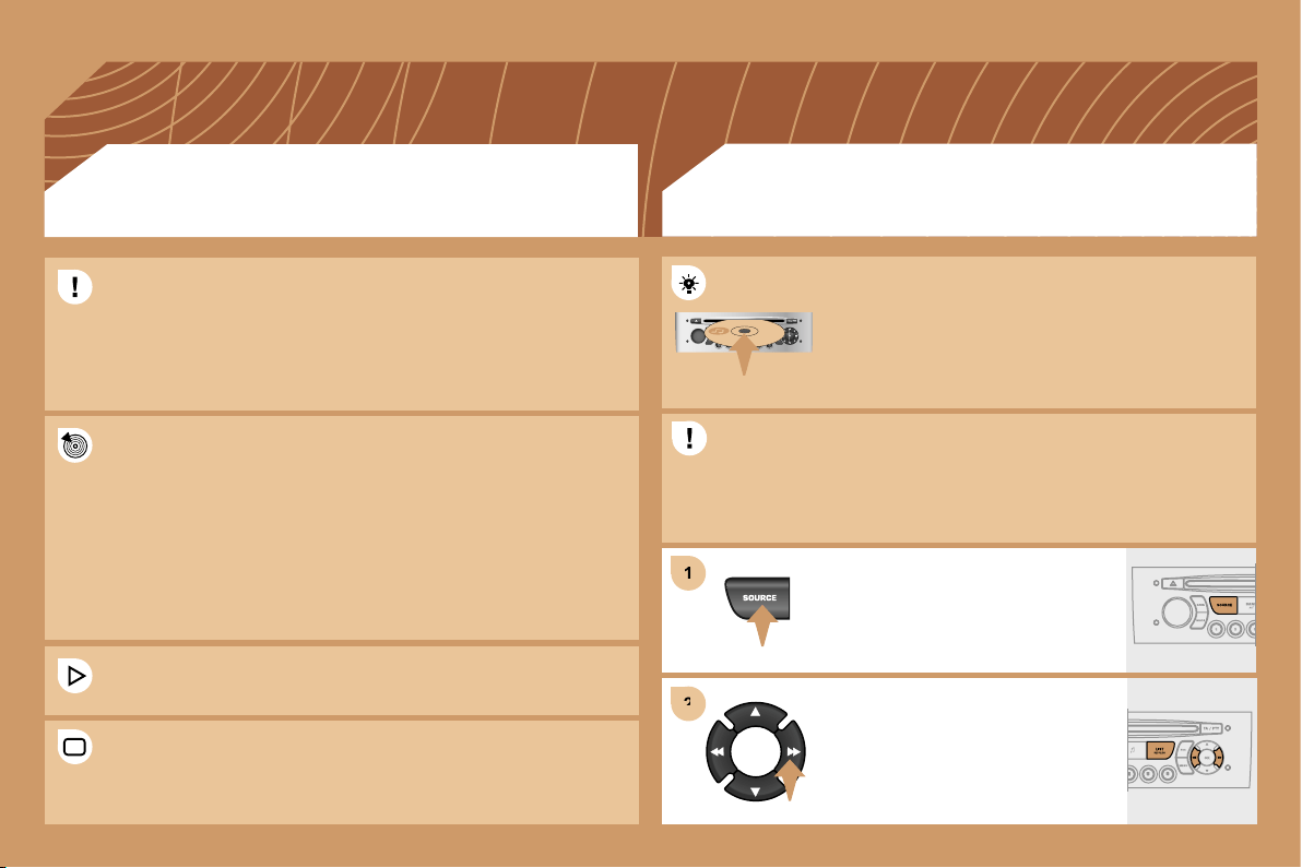
206
1
1
2
2
Insert an MP3 compilation in the player.
The audio equipment searches for all of the music
tracks, which may take anything between a few
seconds and several tens of seconds, before play
begins.
On a single disc, the CD player can read up to 255 MP3 files spread
over 8 directory levels. However, it is advisable to keep to a limit of
two levels to reduce the access time before the CD is played.
CD
PLAYING AN MP3 COMPILATION
MP3 CD
INFORMATION AND ADVICE
The MP3 format, an abbreviation of MPEG 1.2 & 2.5 Audio Layer 3,
is an audio compression standard which permits the recording of
several tens of music files on a single disc.
The playing and displaying of an MP3 compilation may depend on
the recording programme and/or the parameters used.
In order to be able to play a recorded CDR or CDRW, when
recording select standards ISO 9660 level 1.2 or Joliet.
If the disc is recorded in another format, it may not be played
correctly.
It is recommended that the same recording standard is always used
for an individual disc, with as low a speed as possible for optimum
sound quality.
In the particular case of a multi-session CD, the Joliet standard is
recommended.
The audio equipment will only play files with the extension ".mp3".
No other type of file (.wma, .mp4...) can be played.
It is advisable to restrict file names to 20 characters without using
special characters (e.g.: " " ? ; ù) to avoid any playing or displaying
problems.
To play a disc which has already been
inserted, press the SOURCE button
several times in succession and select
CD.
Press one of the buttons to select a
track on the CD.
Press the LIST REFRESH button to
display the list of directories of the
MP3 compilation.
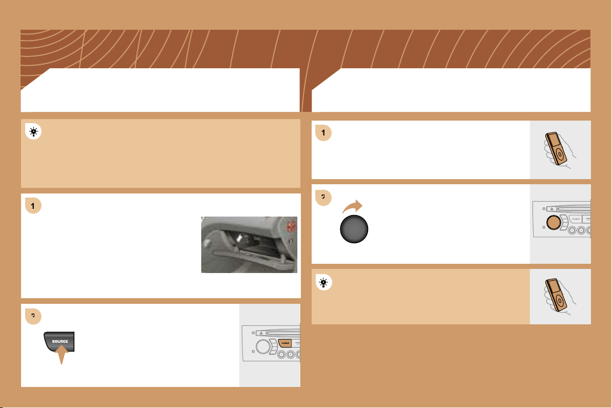
207
1
1
2
2
2
2
1
1
The controls are displayed and managed via the
portable equipment.
First adjust the volume of your portable equipment.
Then adjust the volume of your RD4
audio equipment.
The auxiliary input permits the connection of portable equipment
(MP3 player...). It is activated by default.
Connect the portable equipment (MP3
player…) to the audio sockets (white
and red, RCA type) located in the glove
box using a JACK/RCA audio cable.
Press the SOURCE button several
times in succession and select AUX.
USING THE AUXILIARY INPUT (AUX)
JACK/RCA CABLE NOT SUPPLIED
ADJUSTING THE VOLUME OF
THE AUXILIARY SOURCE
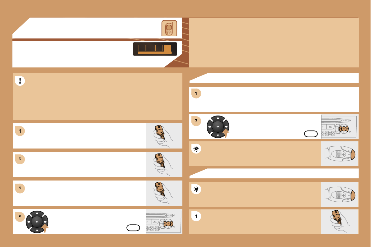
208
1
1
2
2
3
3
1
1
2
2
5
5
1
1
04
HANDS-FREE KIT
MATCHING A TELEPHONE
DISPLAY C
For safety reasons and because they require prolonged attention on
the part of the driver, the operations for matching of the Bluetooth
mobile telephone with the RD4 hands-free kit must be carried out
with the vehicle stationary and the ignition on.
Select the accessory which corresponds to the
name of the vehicle, a superimposed configuration
display appears on the multifunction display.
Activate the telephone’s Bluetooth function and
carry out a search of the Bluetooth accessories
present for the telephone.
Select the YES tab on the display using
the buttons then confirm by pressing OK.
Enter the vehicle’s authentication code (=1234).
Depending on the telephone, you may be asked
to enter this code before the superimposed
configuration display appears.
YES
YES
The services offered by the hands-free kit depend on the network, the SIM card and the compatibility
of the Bluetooth equipment used.
Consult your telephone’s manual and your operator to find out which services are available to you.
A list of mobile telephones which offer the best range of services is available from the network.
Contact a PEUGEOT dealer.
RECEIVING A CALL
An incoming call is announced by a ring and a superimposed display
on the multifunction display.
Select the YES tab on the display
using the buttons and confirm by
pressing OK.
Press the end of the steering wheel stalk to accept
the call.
Press the end of the steering wheel stalk for more
than two seconds to access your directory.
To dial a number, use the keypad on your telephone.
MAKING A CALL
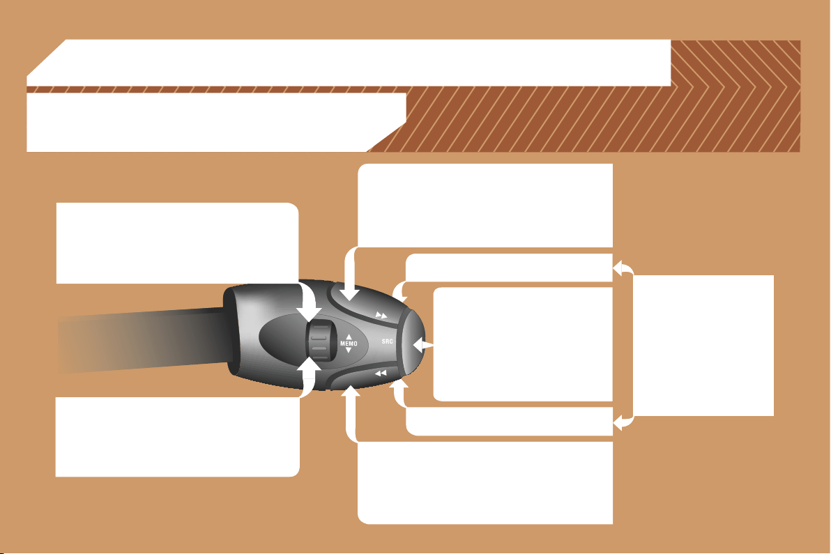
209
05
RADIO: selection of the next stored station.
CD CHANGER: selection of the next CD.
Selection of the next item on a menu.
RADIO: selection of the previous stored station.
CD CHANGER: selection of the previous CD.
Selection of the previous item on a menu.
RADIO: automatic search for a higher frequency.
CD/CD CHANGER/MP3: selection of the next track.
CD/CD CHANGER: continuous press: fast forwards
play.
Selection of the previous item.
RADIO: automatic search for a lower frequency.
CD/CD CHANGER/MP3: selection of the previous
track.
CD/CD CHANGER: continuous press: fast backwards
play.
Selection of the next item.
Volume increase.
Volume decrease.
CONTROL SHORT-CUTS
Mute: by pressing
the volume increase
and decrease buttons
simultaneously.
The sound is restored by
pressing one of the two
volume buttons.
- Change of sound source.
- Confirmation of a selection.
- Pick up/Hang up the telephone.
- Press for more than 2 seconds:
access to the telephone menu.
STEERING WHEEL CONTROLS
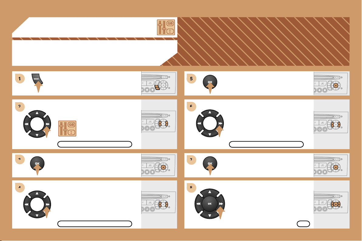
210
5
6
6
7
7
8
8
1
2
2
3
3
4
4
06
CONFIGURATION
ADJUSTING THE DATE AND TIME
DISPLAY C
Press the MENU button.
Using the arrows, select
the PERSONALISATION
CONFIGURATION function.
Press to confirm the selection.
Using the arrows, select the DISPLAY
CONFIGURATION function.
Press to confirm the selection.
Press to confirm the selection.
Using the arrows, select the ADJUST
DATE AND TIME function.
Adjust the parameters one by one
confirming by pressing the OK button.
Next select the OK tab on the display
then confirm.
OK
ADJUST DATE AND TIME
DISPLAY CONFIGURATION
PERSONALISATION CONFIGURATION
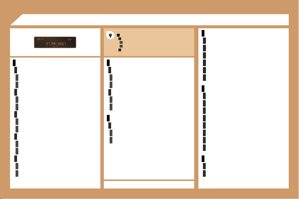
211
1
2
3
3
2
3
3
2
3
3
2
3
3
2
3
3
1
2
3
3
2
3
3
1
2
3
3
1
2
2
2
2
2
2
1
2
2
2
2
2
2
2
2
1
2
2
1
2
3
2
3
07
RADIO-CD
RDS SEARCH
active
inactive
REG MODE
active
inactive
INTROSCAN
active
inactive
CD REPEAT
active
inactive
RANDOM PLAY
active
inactive
VEHICLE CONFIG*
REV WIPE ACT
active
inactive
GUIDE LAMPS
active
inactive
LANGUAGES
FRANCAIS
ITALIANO
NEDERLANDS
PORTUGUES
PORTUGUES-BRASIL
DEUTSCH
ENGLISH
ESPANOL
OPTIONS
ABANDON/CONSULT LIST OF FAULTS
functions activated (or not)
warning messages
DISPLAY ADJUST
YEAR
MONTH
DAY
HOUR
MINUTES
12 H/24 H MODE
UNITS
TEMPERATURE: °CELSIUS/°FAHRENHEIT
FUEL CONSUMPTION: KM/L - L/100 - MPG
DISPLAY FLOW CHART
monochrome A
MAIN FUNCTION
CHOICE A
Choice A1
Choice A2
CHOICE B...
A
* The parameters vary according to vehicle.
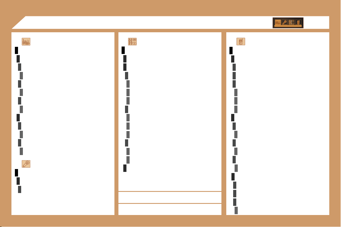
212
1
1
2
3
4
3
4
3
4
2
3
4
3
4
2
3
4
2
4
4
3
4
4
4
3
4
4
1
2
3
2
1
2
3
3
3
4
4
4
2
3
4
3
4
3
4
2
3
3
3
4
07
PERSONALISATION-CONFIGURATION
DEFINE THE VEHICLE PARAMETERS*
DISPLAY CONFIGURATION
video brightness adjustment
normal video
inverse video
brightness (- +) adjustment
date and time adjustment
day/month/year adjustment
hour/minute adjustment
choice of 12 h/24 h mode
choice of units
l/100 km - mpg - km/l
°Celsius/°Fahrenheit
CHOICE OF LANGUAGE
AUDIO FUNCTIONS
FM BAND PREFERENCES
alternative frequencies (RDS)
activate/deactivate
regional mode (REG)
activate/deactivate
radio-text information (RDTXT)
activate/deactivate
AUDIO CD PREFERENCES
cd changer repeat
(RPT)
activate/deactivate
track random play
(RDM)
activate/deactivate
DISPLAY FLOW CHART
monochrome C
* The parameters vary according to vehicle (refer to
the "Multifunction displays" section).
** According to compatibility of Bluetooth telephone
and service contract.
TELEPHONE
CONSULTING DIRECTORIES**
telephone directory
call log
services directory
customer contact centre
breakdown call
emergency call
CONFIGURATION
deletion of a match
list of matches
consulting matches
list of matches
choice of a mobile to connect
list of mobiles
MANAGEMENT OF A COMMUNICATION
switch**
terminate the current call
secret mode
activate/deactivate
VEHICLE DIAGNOSTICS
WARNING LOG
diagnostics