
Es
Fr
En
Basic
Manual
Hookup
Step1: Choose your Speaker Layout ...................................... 3
Step2: Connect the Speakers ................................................. 9
Step3: Connect the TV ......................................................... 12
Step4: Connect the AV Components .................................... 14
Step5: Connect Other Cables ............................................... 18
Setup
Step6: Power On & Initial Setup ........................................... 19
HDMI Setup .......................................................................... 20
Playback
Basic Playback ..................................................................... 21
Network Functions ................................................................ 22
Others ................................................................................... 24
Part Names
Front Panel ........................................................................... 26
Rear Panel ............................................................................ 27
Remote Controller ................................................................ 28
Display .................................................................................. 28
This manual includes information needed when starting up and also
instructions for frequently used operations. The "Advanced Manual" is
available on the internet with details about the playback features/
listening modes/settings details, specifications, and troubleshooting.
The Advanced Manual is created in a format that makes it easy to read
on a PC or Smartphone.
http://www.pioneer-audiovisual.com/manual/vsxlx301/adv/en.html
Advanced Manual found here
VSX-LX301
> Before start > Hookup > Setup > Playback > Part Names
AV Receiver
SN29402194_VSX-301_BAS_En.book 1 ページ 2016年1月6日 水曜日 午前12時5分
2
> Before start > Hookup > Setup > Playback > Part Names
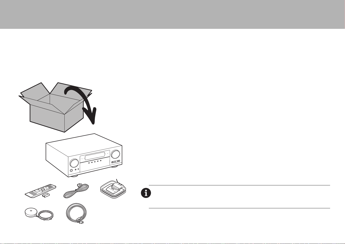
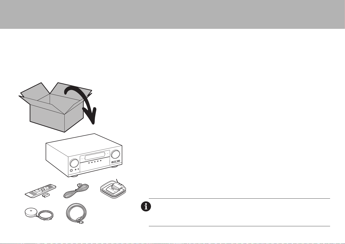
What's in the box
1. Main unit 2. Remote controller (RC-914R)
×1, Batteries (AAA/R03) ×2
3. Indoor FM antenna ×1 4. AM loop antenna ×1 5. Speaker setup microphone ×1
6. Power cord ×1
Main features
This unit is connected between your TV and your AV components. To play, select the source with the input
selector. You can connect 7.1ch of speakers to this unit, with 7ch at 170 W (6 ohms, 1 kHz, 0.9%THD) per
channel plus a powered subwoofer pre out jack.
$
Supports playback in Dolby Atmos format which provides 360e sound placement
$
The HDMI jack supports 4K video input and output. Jacks IN1 to 3 and OUT MAIN/SUB support HDCP2.2
$
HDMI CEC functionality: Control features such as linking input switching with the input selector and players
conforming to the CEC standard, switching audio output and volume using the remote controller of a CEC-
compliant TV, and automatically switching this unit to standby when the TV is turned off
$
HDMI Standby Through: Video and audio signals from AV components can be transmitted to the TV even if this
unit is in standby
$
ARC: Connection with an ARC-compatible TV is complete with one HDMI cable
$
Easy Initial Setup using onscreen guidance and On-Screen Display (OSD) showing operations on the TV
$
Internet radio and AirPlay via wired LAN or Wi-Fi (wireless LAN) and network features such as Music Server
that enables PC music file playback, USB playback, plus other playback features such as AM/FM radio and
BLUETOOTH
®
play
$
Playback formats supported by Music Server and USB include WAV, FLAC and DSD high-res source
$
Multi-zone Connection which allows you to play in the main room and listen in a separate room (ZONE 2)
$
You can connect a speaker B system
$
Equipped with RS-232C port, IR IN/OUT jack, and 12V TRIGGER OUT A/B jacks
$
We plan to provide support for the DTS:X audio format through a firmware update for this unit. Refer to our
homepage for more information.
CAUTION: Connect speakers with 6 Ω to 16 Ω impedance. The power cord must be connected only after
all other cable connections are completed.
0 We will not accept responsibility for damage arising from the connection of equipment manufactured by
other companies.
1
2
56
34
SN29402194_VSX-301_BAS_En.book 2 ページ 2016年1月6日 水曜日 午前12時5分
En
3
> Before start > Hookup > Setup > Playback > Part Names
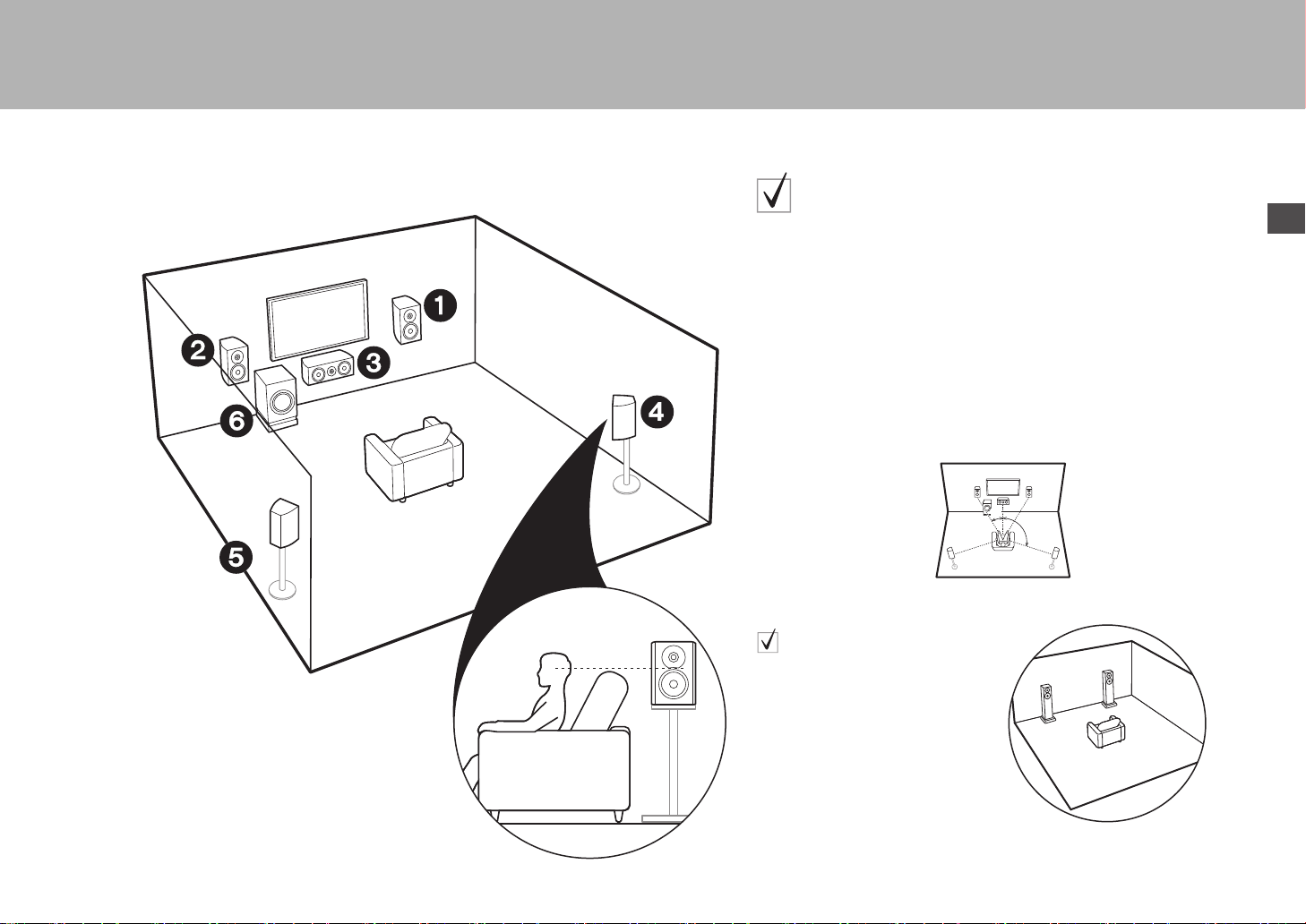
Step1: Choose your Speaker Layout
12
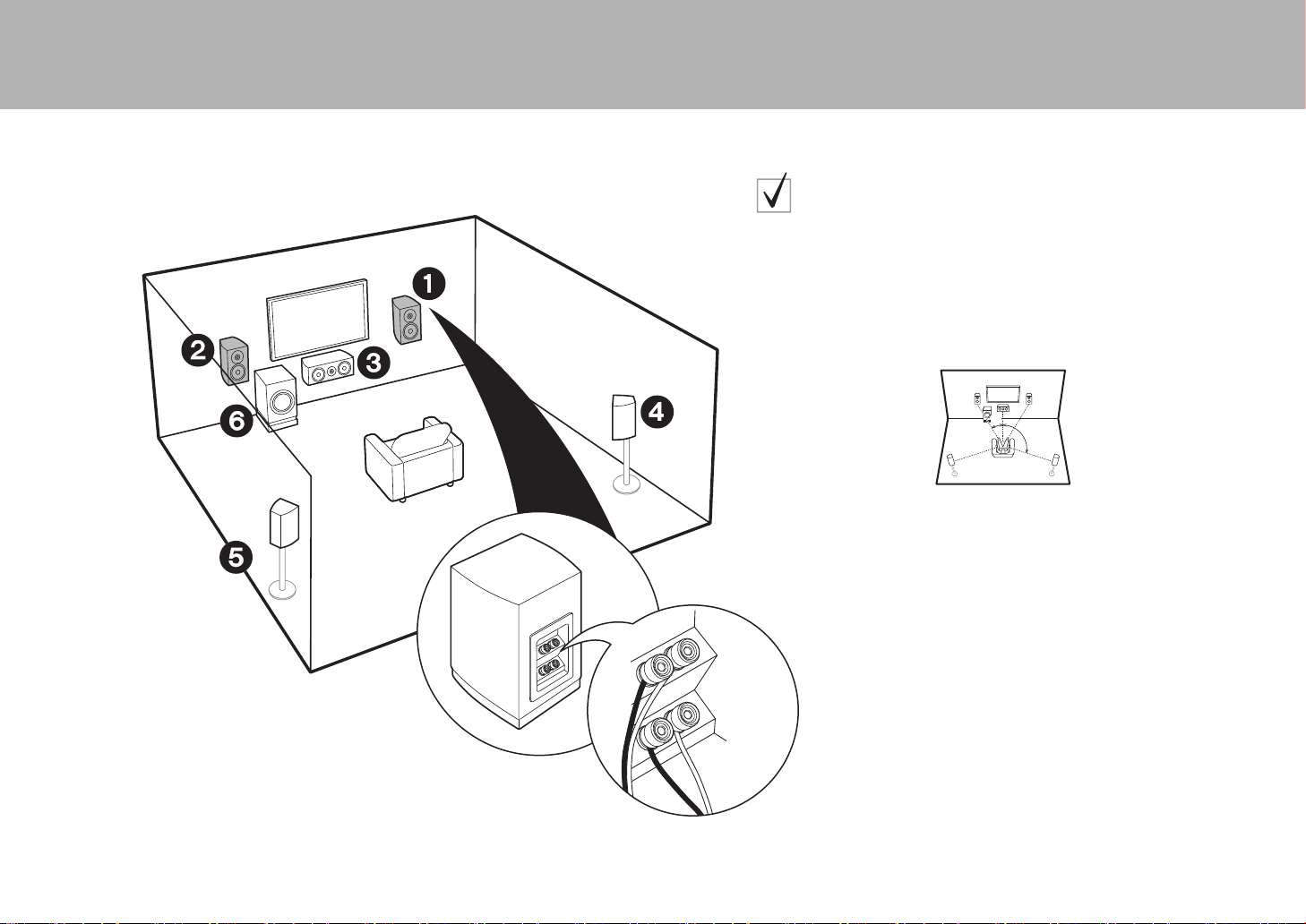
Front Speakers
3
Center Speaker
45
Surround Speakers
6
Powered Subwoofer
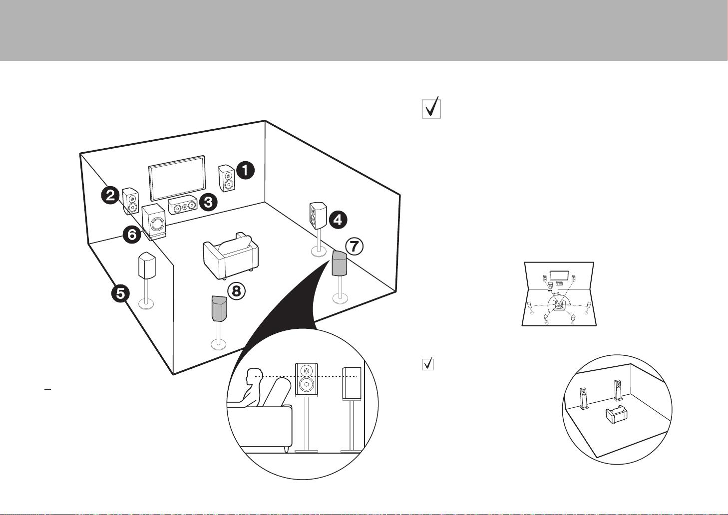
For 5.1-Channel System
This is a 5.1-channel system that is the basic surround system.
Front speakers output front stereo sound and a center speaker outputs center
sound such as dialogs and vocals. Surround speakers create back sound
field. Powered subwoofer reproduces bass sounds and creates rich sound
field. The front speakers should be positioned at ear height, while the
surround speakers should be positioned just above ear height. Center
speaker should be set up facing the listening position. Place the powered
subwoofer towards the front. Placing it between the center speaker and a front
speaker gives you a natural sound even when playing music.
0 The front speakers, center speaker, and surround speakers are counted as
5 channels, and the powered subwoofer is counted as 0.1 of a channel,
giving us the name 5.1ch system.
Go To "Hookup" (
P9)
* 1: 22e to 30e, * 2: 120e
Speaker B System
In a 5.1-Channel System, you can
connect one more set of front
speakers to use as a Speaker B
System. In this state, the 5.1-
Channel System becomes the
Speaker A System and you can
switch the same audio to output from
A, B, or A+B. Note that sound is not
output from Speaker B when Zone
Speaker is used (
P17).
Go To "Hookup" (
P9)
*
1
*
2
SN29402194_VSX-301_BAS_En.book 3 ページ 2016年1月6日 水曜日 午前12時5分
4
> Before start > Hookup > Setup > Playback > Part Names
16
(
P3)
78
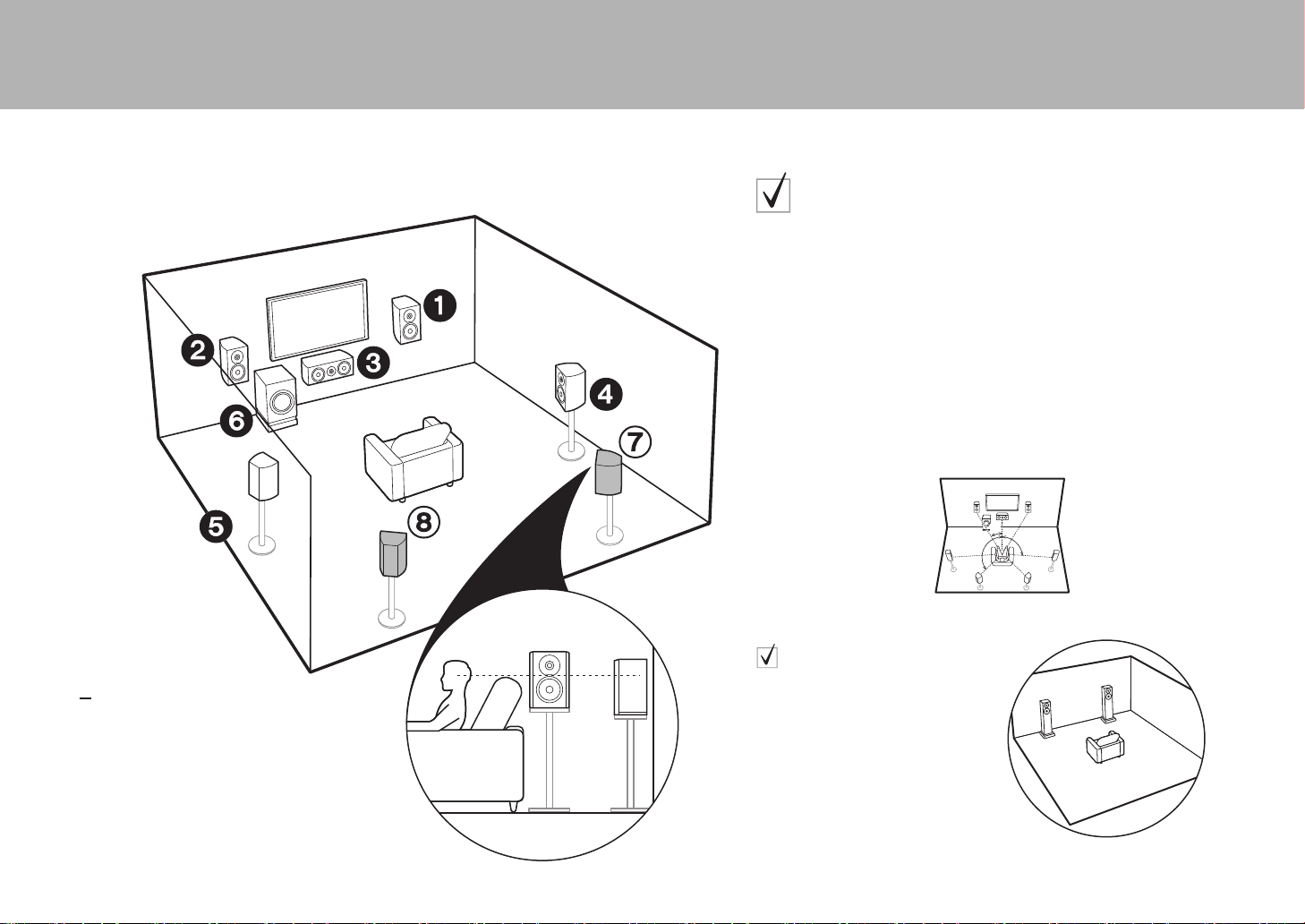
Surround Back Speakers
For 7.1-Channel System (with
Surround Back Speakers)
This is a system with surround back speakers added to the basic 5.1-channel system.
The connection of surround back speakers improves the sense of envelopment and
connectivity of sound created by the back sound field and provides a more real sound
field. You can select the Dolby Atmos listening mode, which realizes the most up-to-date
3D surround sound, when the input format is Dolby Atmos. With formats other than
Dolby Atmos, you can still create a sound field by outputting sound from the surround
back speakers when you select the Dolby Surround listening mode. The optimal
positioning is for surround back speakers to be at ear height. Place the surround
speakers in a more slightly forward position than you would in a 5.1-channel system.
0 If you are including surround back speakers in the setup, surround
speakers are required.
Go To "Hookup" (
P9)
* 1: 22e to 30e, * 2: 90e to 110e, * 3: 135e to 150e
Speaker B System
In a 7.1-Channel System (with Surround
Back Speakers), you can connect one more
set of front speakers to use as a Speaker B
System. In this state, the 7.1-Channel
System becomes the Speaker A System
and you can switch the same audio to
output from A, B, or A+B. Note that sound is
not output from the surround back speaker
when A+B is selected.
Note that sound
is not output from Speaker B when
Zone Speaker is used (
P17)
.
Go To "Hookup" (
P9)
*
2
*
3
*
1
SN29402194_VSX-301_BAS_En.book 4 ページ 2016年1月6日 水曜日 午前12時5分
En
5
> Before start > Hookup > Setup > Playback > Part Names
3´ (0.9 m)
or more
16
(
P3)
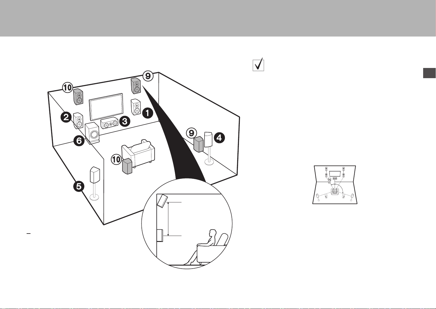
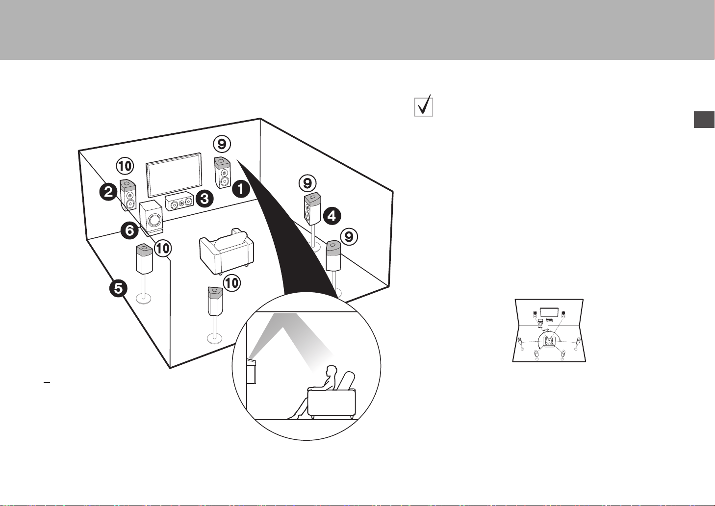
9:
Height Speakers
Choose one of the following:
$
$
Front High Speakers
Rear High Speakers
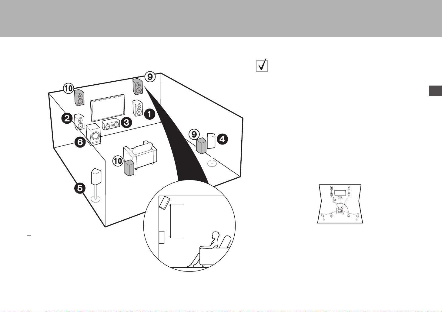
For 7.1-Channel System
(with Height Speaker-A)
This is a basic 5.1-channel system with the addition of height speakers, either
as front high speakers or rear high speakers. Select which speakers to setup
according to the environment of the room. You can select the Dolby Atmos
listening mode (5.1.2 channel playback), which realizes the most up-to-date
3D surround sound including overhead sounds, when the input format is Dolby
Atmos. With formats other than Dolby Atmos, you can still create a sound field
by outputting sound from the height speakers when you select the Dolby
Surround listening mode. Front high speakers or rear high speakers should be
situated at least 0.9 m higher than the front speakers. Front high speakers
should be situated directly above the front speakers and the distance between
the rear high speakers should match the distance between the front speakers.
Both should be set up facing the listening position.
Go To "Hookup" (
P10)
* 1: 22e to 30e, * 2: 120e
*
1
*
2
SN29402194_VSX-301_BAS_En.book 5 ページ 2016年1月6日 水曜日 午前12時5分

6
> Before start > Hookup > Setup > Playback > Part Names
16
(
P3)
9:
Height Speakers
Choose one of the following:
$
$
$
Top Front Speakers
Top Middle Speakers
Top Rear Speakers
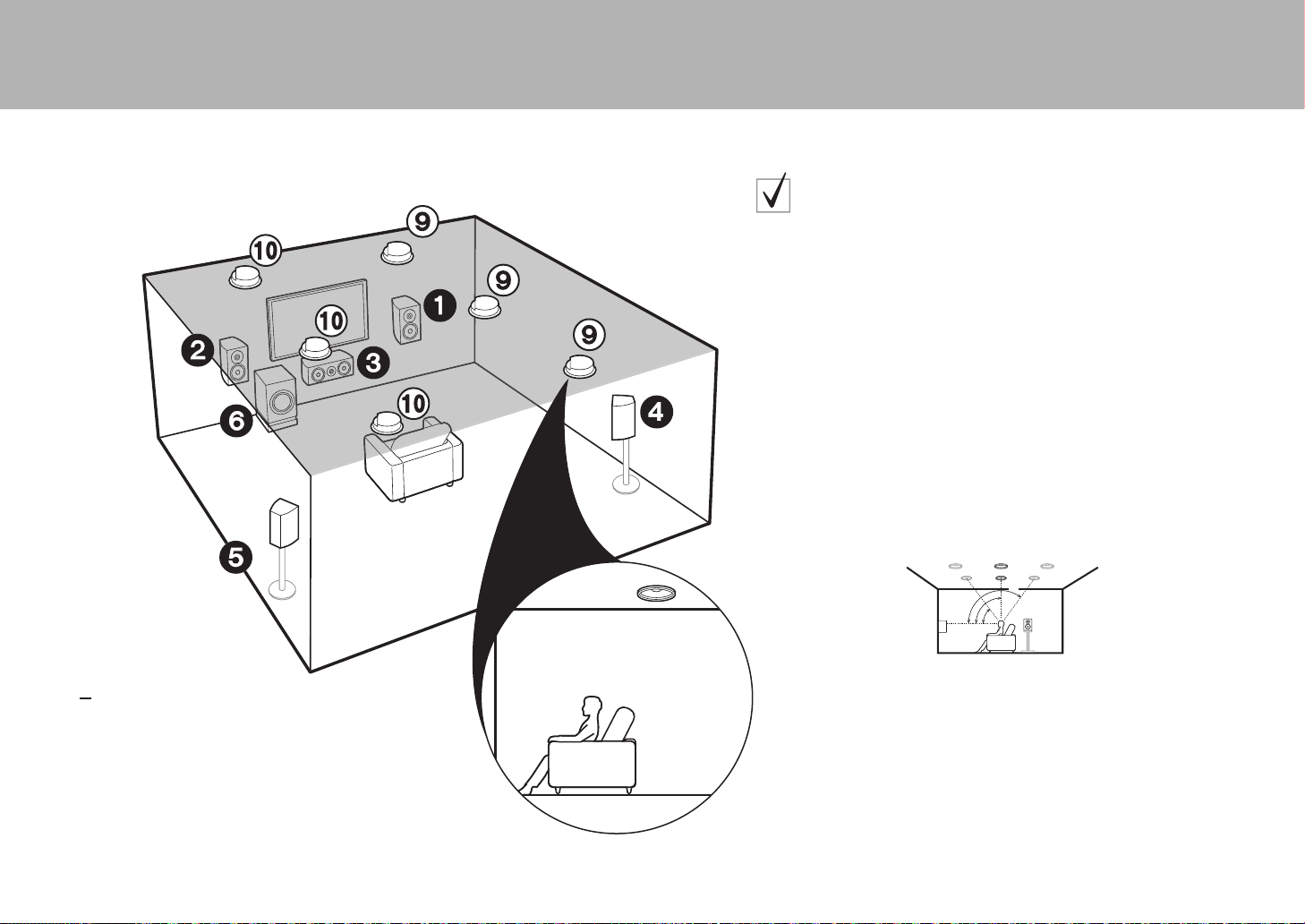
For 7.1-Channel System
(with Height Speaker-B)
This is a basic 5.1-channel system using ceiling speakers, for example, with
the addition of height speakers, either as top front speakers, top middle
speakers, or top rear speakers. Select which speakers to setup according to
the environment of the room. You can select the Dolby Atmos listening mode
(5.1.2 channel playback), which realizes the most up-to-date 3D surround
sound including overhead sounds, when the input format is Dolby Atmos. With
formats other than Dolby Atmos, you can still create a sound field by
outputting sound from the height speakers when you select the Dolby
Surround listening mode. Fit top front speakers on the ceiling forward of the
seating position, top middle speakers on the ceiling directly above the seating
position, and top rear speakers on the ceiling behind the seating position. The
distance between each pair should match the distance between the two front
speakers.
0 Dolby Laboratories recommends placing this type of height speakers to
obtain the best Dolby Atmos effect.
Go To "Hookup" (
P10)
* 1: 30e to 55e, * 2: 65e to 100e, * 3: 125e to 150e
*
1
*
2
*
3
SN29402194_VSX-301_BAS_En.book 6 ページ 2016年1月6日 水曜日 午前12時5分
En
7
> Before start > Hookup > Setup > Playback > Part Names
16
(
P3)
9:
Height Speakers
Choose one of the following:
$
$
$
Dolby Enabled Speakers (Front)
Dolby Enabled Speakers (Surround)
Dolby Enabled Speakers (Surround Back)
For 7.1-Channel System
(with Height Speakers-C)
This is a basic 5.1-channel system that using Dolby enabled speakers, with
the addition of height speakers, either as Dolby enabled speakers (front) or
Dolby enabled speakers (surround) or Dolby enabled speakers (surround
back). Select which speakers to setup according to the environment of the
room. Dolby enabled speakers are special speakers designed to face the
ceiling so that sound is heard after bouncing off the ceiling so that sound
appears to be coming from overhead. You can select the Dolby Atmos
listening mode (5.1.2 channel playback), which realizes the most up-to-date
3D surround sound including overhead sounds, when the input format is Dolby
Atmos. With formats other than Dolby Atmos, you can still create a sound field
by outputting sound from the height speakers when you select the Dolby
Surround listening mode. Place them either above the front speakers or above
the surround speakers or surround back speakers. If they are integrated Dolby
enabled speakers, put in place of the front speakers, the surround speakers,
or the surround back speakers.
Go To "Hookup" (
P10)
* 1: 22e to 30e, * 2: 90e to 120e, * 3: 135e to 150e
*
1
*
2
*
3
SN29402194_VSX-301_BAS_En.book 7 ページ 2016年1月6日 水曜日 午前12時5分
8
> Before start > Hookup > Setup > Playback > Part Names
12
Front Speakers (Bi-Amping)
3
Center Speaker
45
Surround Speakers
6
Powered Subwoofer
For Bi-Amping the Speakers
It is possible to connect front speakers supporting Bi-Amping to improve
quality of the bass and treble. The maximum number of channels available
with this connection is 5.1 because Bi-Amping speakers require one amplifier
for the tweeter jacks and one amplifier for the woofer jacks. The effects and
placements for speakers are the same as the 5.1-channel plan that doesn't
use Bi-Amping speakers.
Go To "Hookup" (
P11)
* 1: 22e to 30e, * 2: 120e
*
1
*
2
SN29402194_VSX-301_BAS_En.book 8 ページ 2016年1月6日 水曜日 午前12時5分
En
9
> Before start > Hookup > Setup > Playback > Part Names
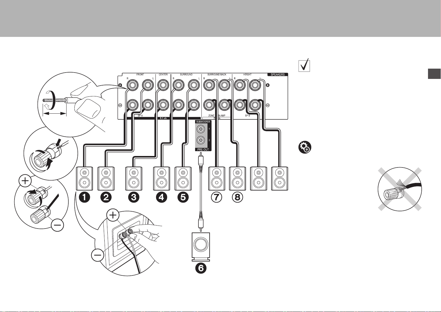
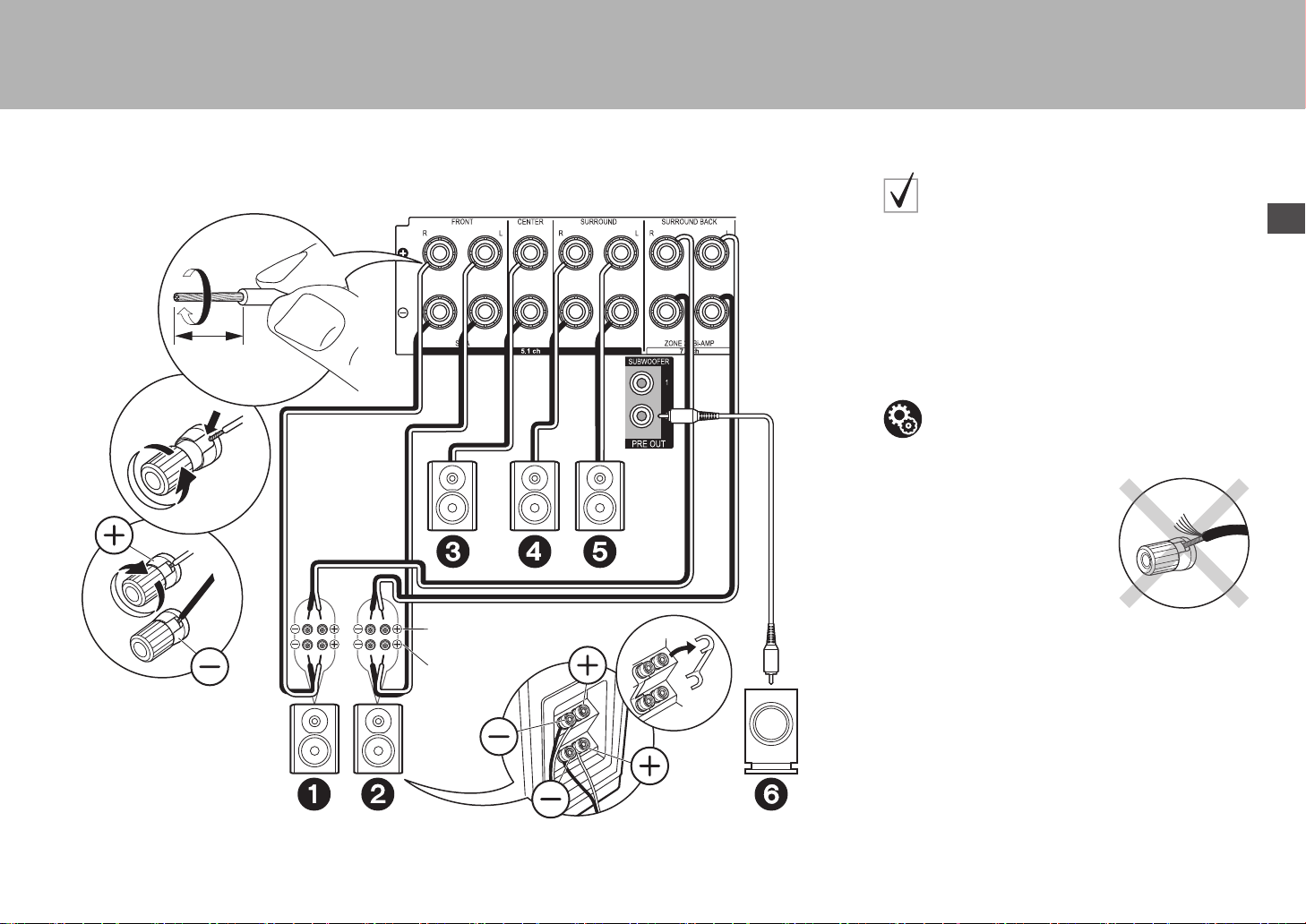
Step2: Connect the Speakers
2
1
1/2˝
(12 mm)
Speaker B
1 Speaker cable, 2 Subwoofer cable
in case of:
Pages 3 to 4
Connect 123456 for a 5.1-channel system. With a
7.1-Channel System (with Surround Back Speakers), also
connect 7 and 8. Up to two powered subwoofers can be
connected. The same signal is output from each of the
SUBWOOFER jacks. With this connection, you can
connect one more set of front speakers to use as a
Speaker B System. Switch Speakers A/B with AV Adjust
(
P25). Note that sound is not output from the surround
back speaker when A+B is selected.
Make sure the exposed wires of the speakers do not stick out of
the speaker terminals when connecting. If the exposed wires of
the speakers touch the rear panel or the + and – wires touch each
other, the protection circuit will be activated.
Setup
0 Settings for the speaker configuration you have
connected need to be made in "1. Full Auto
MCACC" (
P19) in Initial Setup.
SN29402194_VSX-301_BAS_En.book 9 ページ 2016年1月6日 水曜日 午前12時5分
10
> Before start > Hookup > Setup > Playback > Part Names
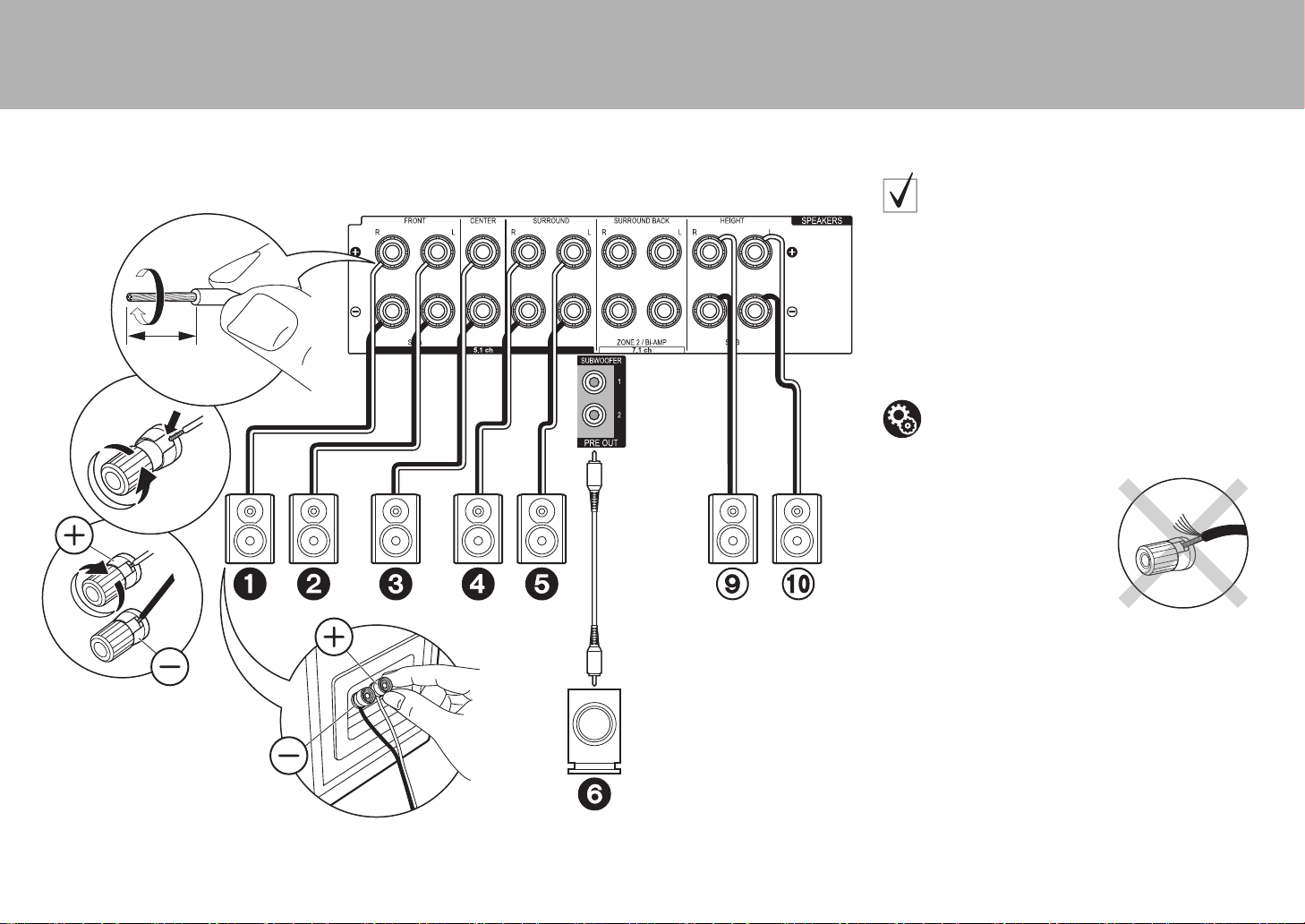
2
1
1/2˝
(12 mm)
1 Speaker cable, 2 Subwoofer cable
in case of:
Pages 5 to 7
Connect 1234569:. Up to two powered
subwoofers can be connected. The same signal is output
from each of the SUBWOOFER jacks.
0 Apart from these connections, you can also connect
surround back speakers ⑦ and ⑧ . However, you can
only output audio from one set of ⑦⑧ or ⑨⑩ at a time.
When both are connected, you can select which
speakers to prioritize with AV Adjust (
P25).
Make sure the exposed wires of the speakers do not stick out of
the speaker terminals when connecting. If the exposed wires of
the speakers touch the rear panel or the + and – wires touch each
other, the protection circuit will be activated.
Setup
0 Settings for the speaker configuration you have
connected need to be made in "1. Full Auto
MCACC" (
P19) in Initial Setup.
SN29402194_VSX-301_BAS_En.book 10 ページ 2016年1月6日 水曜日 午前12時5分
En
11
> Before start > Hookup > Setup > Playback > Part Names
1
2
1/2˝
(12 mm)
For high-
frequency
For low-
frequency
1 Speaker cable, 2 Subwoofer cable
in case of:
Page 8
Connect front speakers compatible with Bi-Amping
connection to the FRONT jacks and the SURROUND
BACK jacks. Make sure you remove the jumper bar fitted
between the woofer jacks and tweeter jacks of the front
speakers. In case of Bi-Amping connection, refer to the
instruction manual of your speakers. Up to two powered
subwoofers can be connected. The same signal is output
from each of the SUBWOOFER jacks.
Make sure the exposed wires of the speakers do not stick out of
the speaker terminals when connecting. If the exposed wires of
the speakers touch the rear panel or the + and – wires touch each
other, the protection circuit will be activated.
Setup
0 Bi-Amping connection requires you to change
some settings. Select "Yes" in "Bi-Amp" in "1. Full
Auto MCACC" (
P19) in the Initial Setup.
SN29402194_VSX-301_BAS_En.book 11 ページ 2016年1月6日 水曜日 午前12時5分
12
> Before start > Hookup > Setup > Playback > Part Names
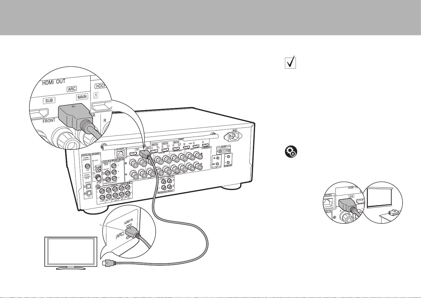
Step3: Connect the TV
HDMI IN (ARC)
1
TV
1 HDMI cable
if you have:
ARC TV
This unit is connected between your TV and AV
components. If you connect two or more AV components,
you can select the video displayed on the TV and the
audio output from this unit by changing the input selector.
Shown here are the connections for a TV that supports
the ARC (Audio Return Channel) feature. By connecting
with a single HDMI cable, you can not only output the
video input to this unit to the TV, but you can also play the
sound from the TV through this unit.
Choose an HDMI IN jack on the TV that supports ARC
when connecting.
Another TV or projector can be connected to the HDMI OUT SUB
jack. This jack does not support ARC. For details about how to
output the video to a connected device (P21)
Setup
0 Settings are required to use the ARC function.
Select "Yes" in "5. Audio Return Channel" (
P20)
in the Initial Setup.
0 Please refer to the TV's operation manual for
directions on connections and setup for the TV.
SN29402194_VSX-301_BAS_En.book 12 ページ 2016年1月6日 水曜日 午前12時5分
En
13
> Before start > Hookup > Setup > Playback > Part Names
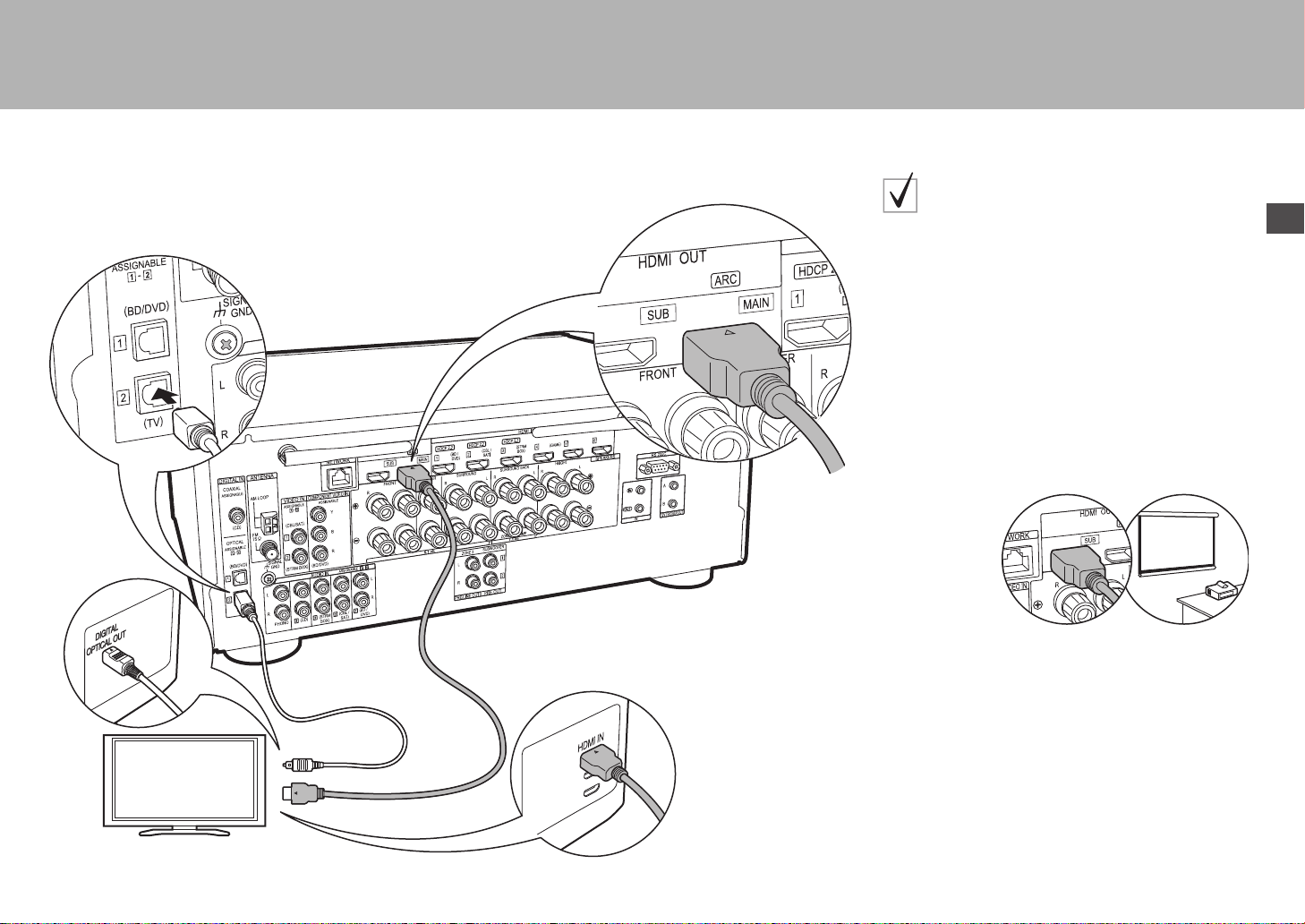
TV
12
1 HDMI cable, 2 Digital optical cable
if you have:
Non-ARC TV
This unit is connected between your TV and AV
components. If you connect two or more AV components,
you can select the video displayed on the TV and the
audio output from this unit by changing the input selector.
This describes the connections for a TV that does not
support the ARC (Audio Return Channel) feature. By
connecting with both an HDMI cable and a digital optical
cable, you can not only output the video input to this unit
to the TV, but you can also play the sound from the TV
through this unit.
0 Connection with a digital optical cable is not necessary
if you will watch TV through a device such as a cable
set-top box (that is, not use a tuner built into the TV).
Another TV or projector can be connected to the HDMI OUT SUB
jack. This jack does not support ARC. For details about how to
output the video to a connected device (P21)
SN29402194_VSX-301_BAS_En.book 13 ページ 2016年1月6日 水曜日 午前12時5分

14
> Before start > Hookup > Setup > Playback > Part Names
Step4: Connect the AV Components
BD/DVD
GAME
1
Cable/Satellite set-top
box
Streaming media
player
1 HDMI cable
if you have:
HDMI AV Components
This is an example of connection with an AV component
that has an HDMI jack. With connection to an AV
component that conforms with the CEC (Consumer
Electronics Control) standard, you can use features such
as the HDMI CEC feature that links with the input selector,
and the HDMI Standby Through feature which allows you
to play video and audio from AV components on the TV
even when this unit is in standby mode.
0 To play 4K or 1080p video, use a high speed HDMI
cable. Further, to enjoy HDCP2.2 compatible video,
connect to the HDMI IN1 to IN3 jacks.
You can connect a device such as a video camera to the AUX
INPUT HDMI jack on the front panel.
Setup
0 HDMI setup (
P20) is required to use the HDMI
CEC and HDMI Standby Through features. Make
settings after all connections are complete.
0 To enjoy digital surround sound including Dolby
Digital, audio output should be set to "Bitstream
output" on the connected Blu-ray Disc player or
other device.
SN29402194_VSX-301_BAS_En.book 14 ページ 2016年1月6日 水曜日 午前12時5分
En
15
> Before start > Hookup > Setup > Playback > Part Names
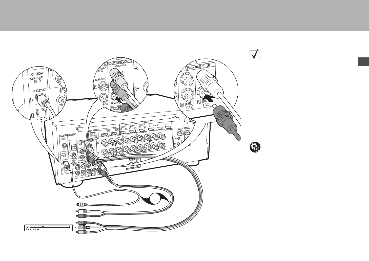
OR
BD/DVD
1
2
3
1 Component video cable, 2 Digital optical cable, 3 Analog audio cable
if you have:
Non-HDMI AV Components
This is an example of connection with an AV component
that does not have an HDMI jack. Make the connections
to the AV component to match the jacks it has. When
video input connection is to the BD/DVD jack, the audio
input connection should also be to the BD/DVD jacks, and
so on, so that you connect the video input jacks to the
jacks with the same name as the audio input jacks. Note
that video signals input to the VIDEO IN jack or the
COMPONENT VIDEO IN jacks will be upconverted to
HDMI signals and then output from the HDMI OUT jack.
0 To enjoy digital surround playback in formats such as
Dolby Digital, you need to make a connection for audio
signals with a digital coaxial cable or digital optical
cable.
Setup
0 The COMPONENT VIDEO IN jacks are
compatible only with 480i or 576i resolution. When
you input video signals to the COMPONENT
VIDEO IN jacks, set the output resolution of the
player to 480i or 576i. Select interlace if there is no
option for 480i, etc. If your player does not support
480i or 576i output, use the VIDEO IN jack.
0 To enjoy digital surround sound including Dolby
Digital, audio output should be set to "Bitstream
output" on the connected Blu-ray Disc Player or
other device.
SN29402194_VSX-301_BAS_En.book 15 ページ 2016年1月6日 水曜日 午前12時5分
16
> Before start > Hookup > Setup > Playback > Part Names
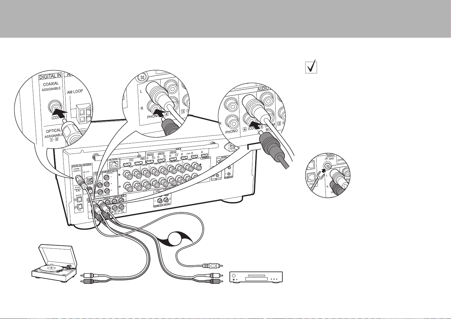
OR
CD
2
1
Turntable
1 Digital coaxial cable, 2 Analog audio cable
if you have:
Audio Components
Example of a connection with an audio component.
Connect a CD player using a digital coaxial cable or
analog audio cable. You can also connect a turntable that
has an MM-type cartridge to the PHONO jack.
0 If the turntable has a built-in audio equalizer, connect it
to another AUDIO IN jack. Further, if the turntable uses
an MC type cartridge, install an audio equalizer
compatible with the MC type cartridge between the unit
and the turntable, then connect to any AUDIO IN jack
other than the PHONO jack.
If the turntable has a ground wire, connect it to the SIGNAL GND
terminal of this unit.
SN29402194_VSX-301_BAS_En.book 16 ページ 2016年1月6日 水曜日 午前12時5分

En
17
> Before start > Hookup > Setup > Playback > Part Names
BD/DVD
ZONE2 PRE/LINE OUT
ZONE SPEAKER
1
2
ZONE2
LINE
IN
MAIN ROOM
1 Analog audio cable, 2 Speaker cable
Multi-zone Connection
You can enjoy audio in the separate room by, for example,
playing a Blu-ray Disc player in the main room (where this
unit is located) and listening to internet radio in the
separate room (ZONE 2).
0 DSD and Dolby TrueHD audio signals are not output to
ZONE 2 when selected with the "NET" input selector.
Connections with an AV component
When outputting the audio of an external AV component
to ZONE 2, you need to connect using an analog audio
cable.
ZONE 2 PRE/LINE OUT
It is possible to play 2 ch source in a separate room while
7.1 ch source is being played in the main room. Connect
the ZONE 2 PRE/LINE OUT jacks of the unit and the
LINE IN jacks of the pre-main amplifier or the powered
amplifier in a separate room with an analog audio cable.
ZONE SPEAKER
It is possible to connect speakers in a separate room and
play 2 ch sources.
0 You can play through a maximum of 5.1 channels in the
main room during ZONE 2 playback. Listening modes
such as the Dolby Atmos modes cannot be selected.
0 Note that sound is not output from Speaker B when
Zone Speaker is used.
Setup
0 Settings are required in Initial Setup, "4. Multi
Zone Setup" (
P20) to enjoy this feature.
SN29402194_VSX-301_BAS_En.book 17 ページ 2016年1月6日 水曜日 午前12時5分
18
> Before start > Hookup > Setup > Playback > Part Names
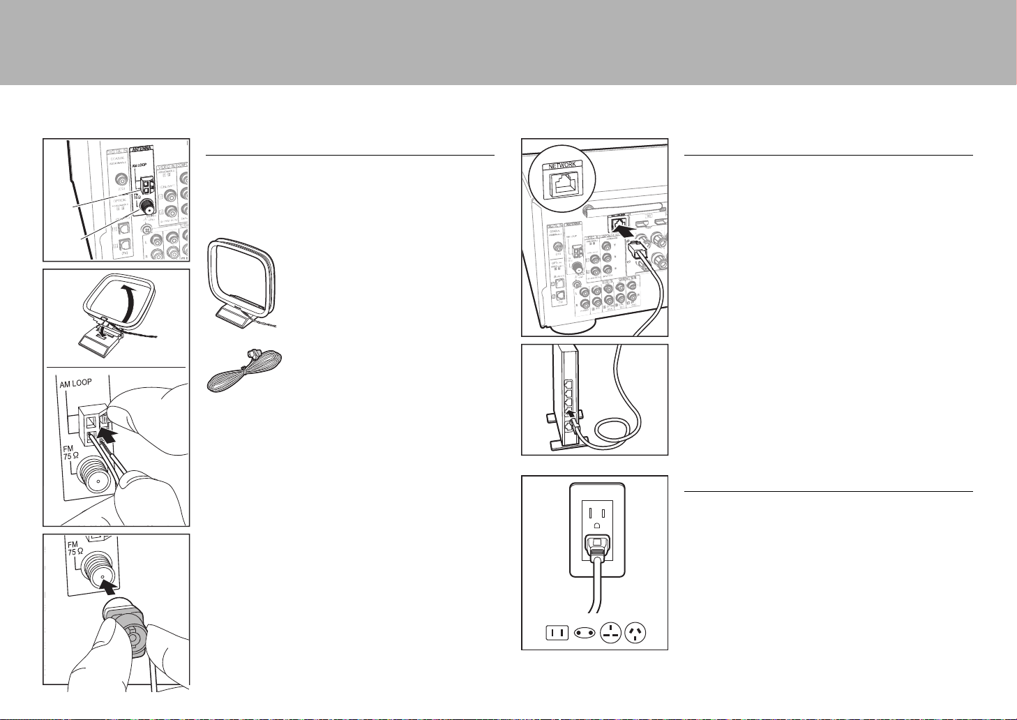
Step5: Connect Other Cables
Antenna Hookup
Move the antenna around while playing the radio to find
the position with the best reception. Use a thumb tack or
similar to attach the indoor FM antenna to a wall.
AM loop antenna
Indoor FM antenna
AM
FM
Network Hookup
Connect this unit to the network using wired LAN or Wi-Fi
(wireless LAN). You can enjoy network features such as
internet radio, Music Server, and AirPlay by connecting the
unit to the network.
If you connect by wired LAN, connect with an Ethernet
cable to the NETWORK port as shown in the illustration.
To connect by Wi-Fi, then after selecting "Wireless" in "3.
Network Connection" (
P20) in Initial Setup, select the
desired setting method and follow the onscreen
instructions to configure the connection.
Power Cord Hookup
This unit includes removable power cords. Connect the
power cord to the power outlet after completing all other
connections. Connect the power cord to AC IN of the unit
and then connect to the outlet. Always disconnect the
outlet side first when disconnecting the power cord.
SN29402194_VSX-301_BAS_En.book 18 ページ 2016年1月6日 水曜日 午前12時5分
En
19
> Before start > Hookup >Setup > Playback > Part Names
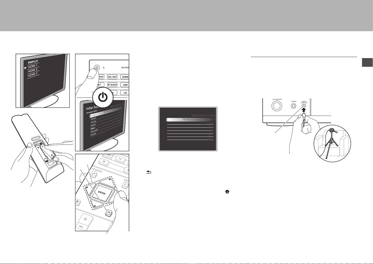
Step6: Power On & Initial Setup
Initial Setup starts automatically
Once all connections are complete, change the TV's input
to the input for this unit, inset batteries in the remote
controller, and press Í to turn the power on. When you
turn the unit on for the first time, Initial Setup is
automatically shown on the TV to enable you to make
settings required for startup using simple operations
following onscreen guidance.
These instructions will guide you through some items that
you need to check beforehand. Read beforehand so the
setup goes smoothly.
Operation
Select the item with the cursors of the remote controller
and press ENTER (a). To return to the previous screen,
press (b).
To redo the Initial Setup
If you terminate the procedure on the way or want to
change a setting made during Initial Setup, press on
the remote controller, select "System Setup" –
"Miscellaneous" – "Initial Setup" from Home, and press
ENTER.
1. Full Auto MCACC
Place the supplied speaker setup microphone in the
listening position, measure the test tones emitted by the
speakers, then the unit automatically sets the optimum
volume level for each speaker, the crossover frequencies,
and the distance from the listening position. This also
enables correction of distortion caused by the acoustic
environment of the room.
0 Use a tripod or similar to place the speaker setup
microphone at ear height.
0 The subwoofer sound may not be detected since it is
extremely low frequencies. Set the subwoofer volume to
more than halfway.
0 Calibration takes several minutes to be completed. The
speakers emit the test tone at high volume during
measurement, so be careful of your surroundings. Keep
the room as quiet as possible during measurement. If
the measurement is interrupted, turn off the household
appliances.
a
b
Initial Setup
Language Select
English
Deutsch
Français
Español
Italiano
Nederlands
Svenska
MCACC
SETUP MIC
SN29402194_VSX-301_BAS_En.book 19 ページ 2016年1月6日 水曜日 午前12時5分

20
> Before start > Hookup >Setup > Playback > Part Names
2. Source Connection
Check that each input source is connected correctly. Follow
the guidance, select the input you want to confirm, start
play of the selected player, and confirm that the images
appear on the TV and that sound is played.
3. Network Connection
Set up Wi-Fi connection with an access point such as a
wireless LAN router. There are the following two methods of
connecting by Wi-Fi:
"Scan Networks": Search for an access point from this
unit. Find out the SSID of the access point beforehand.
"Use iOS Device (iOS7 or later)": Share the iOS device's
Wi-Fi settings with this unit.
If you select "Scan Networks", there are a further two
choices of connection method. Check the following.
0 "Enter Password": Enter the password (or key) of the
access point to connect.
0 "Push Button": If the access point has an automatic
connection button, you can connect without entering a
password.
0 If the SSID of the access point is not displayed, then in
the screen listing the SSIDs, select "Other..." with the
cursor on the remote controller and press ENTER, then
follow the onscreen instructions.
Keyboard input
To switch between upper and lower case, select "A/a" on
the screen and press ENTER. To select whether to mask
the password with "*" or display it in plain text, press +Fav
on the remote controller. Press CLEAR to delete all the
input characters.
0 A confirmation screen asking you to agree to the privacy
policy is displayed during network setting. Select "Yes"
and press ENTER to indicate agreement.
4. Multi Zone Setup
When you want to enjoy audio in a room other than the
main room, set the audio output method for the separate
room (ZONE2). If you have connected speakers in a
separate room with speaker cable, select "Using AV
Receiver". If you have connected a pre-main amplifier in a
separate room with an analog audio cable, select "with
External Premain Amplifier". If you have connected a power
amplifier, select "with External Power Amplifier".
5. Audio Return Channel
If you have connected a TV that supports ARC, select
"Yes". This unit's ARC setting turns on and you can listen to
the TV's audio through this unit.
Wi-Fi Setup
SSID
When finished, select the "OK" key.
**
OKA/a
a b cdef gh i jklm
nopqr s tuvwxy z
1 2 3456789 0-^ \
,./;:@[]
A/aAll Erase
HDMI Setup
HDMI CEC
Make this setting to enable the control feature for devices
complying with the CEC standard. This is set to on
automatically if you have selected "Yes" in "5. Audio Return
Channel" in the Initial Setup.
Press the button on the remote controller to set "System
Setup" – "Hardware" – "HDMI" – "HDMI CEC" to "On" on
the TV screen. Also enable the CEC control feature on the
CEC device you have connected.
HDMI Standby Through
Even if this unit is in standby, the input signals from AV
components are transmitted to the TV.
0 "Auto" / "Auto (Eco)": Select one of these settings
when connected AV components comply with the CEC
standard. Irrespective of the input selector selected
immediately before switching the unit to standby, you can
transmit the input signals from AV components to the TV.
Select "Auto (Eco)" if the TV is also CEC-compliant. You
can reduce power consumption in standby mode.
0 "Input selector names for BD/DVD, etc.": You can
transmit the input signals from the set input selector to
the TV. It can be selected when "HDMI CEC" is set to
"Off".
0 "Last": You can transfer the input signals of the input
selector selected immediately prior to the unit being
switched to standby. It can be selected when "HDMI
CEC" is set to "Off".
To exit the settings, press .
HDMI
HDMI CEC
HDMI Standby Through
Audio TV Out
Audio Return Channel
Auto Delay
On
Auto(Eco)
Auto
Auto
On
SN29402194_VSX-301_BAS_En.book 20 ページ 2016年1月6日 水曜日 午前12時5分
En
21
> Before start > Hookup > Setup > Playback >Part Names
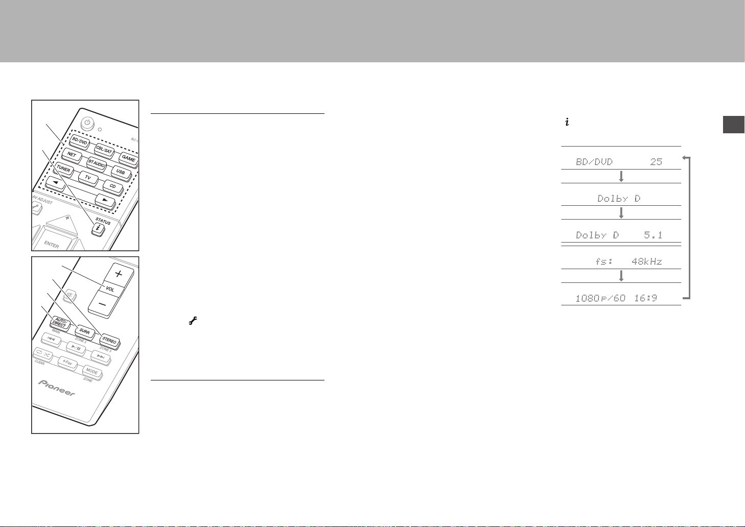
Basic Playback
AV Component Playback
1. Switch the input on the TV to that assigned to
the unit.
2. Press the input selector (a) on the remote
controller with the same name as the jack to
which you connected the player to switch the
input.
For example, press BD/DVD to play the
player connected to the BD/DVD jack. Press
TV to listen the TV's sound.
You can also select input with the 21
buttons.
0 When the CEC link function works, the
input switches automatically when you
have connected a CEC compliant TV and
player to this unit using HDMI connection.
3. Start play on the player.
4. Use VOL+/– (b) to adjust the volume.
When a TV is connected to the HDMI OUT
SUB jack
Press the button on the remote controller to
display the AV Adjust, and set "Other" – "HDMI
Out" to either "SUB" or "MAIN+SUB".
Listening Mode
This unit is equipped with a variety of listening
modes. For details on the listening modes, see
the Advanced Manual. This section introduces
some of the popular modes.
0 A future firmware update is planned to enable
this unit to support playback in DTS Neural:X
audio format. Neo:6 Cinema and Neo:6 Music
are available until an update.
AUTO/DIRECT button (c)
You can select the Auto Surround, Direct, and
Pure Direct modes. In either case, for 2 channel
input signals the Stereo mode is automatically
selected that plays only from the front speakers
and subwoofer, and for multi-channel input
signals listening modes are automatically
selected that match the input signal, so Dolby
Digital for Dolby Digital sources, and DTS-HD
Master Audio for DTS-HD Master Audio. The
Direct mode shuts down some processing that
can affect sound quality, such as the tone
control features, so you can enjoy even better
sound quality. The Pure Direct mode shuts
down even more processes that affects sound
quality, so you get a more faithful reproduction
of the original sound. In this case, the speaker
calibration made with MCACC is disabled.
0 Depending on the input signal and speaker
configuration, the Dolby Surround and DTS
Neural:X modes that expand 2 channel and
5.1 channel input signals to 5.1 channel and
7.1 channel may be automatically selected.
SURR button (d)
You can select a variety of listening modes to
suit your taste. There are the Dolby Digital,
DTS-HD Master Audio, and Stereo modes that
you can choose to suit the input signal, or the
Dolby Surround and DTS Neural:X modes that
can expand 2 channel and 5.1 channel input
signals to 5.1 or 7.1 channels. You can also
enjoy original surround modes such as
Ext.Stereo and Drama modes.
STEREO button (e)
You can select the "Stereo" mode to playback
only from the front speakers and subwoofer.
The listening mode last selected for the source
is remembered for each of the AUTO/DIRECT,
SURR, and STEREO buttons. If content you
play is not supported by the listening mode you
selected last, the listening mode that is standard
for that content is selected automatically.
Press (f) repeatedly to switch the display of
the main unit in order of:
f
a
b
c
d
e
SN29402194_VSX-301_BAS_En.book 21 ページ 2016年1月6日 水曜日 午前12時5分
22
> Before start > Hookup > Setup > Playback >Part Names
Network Functions
Network Services
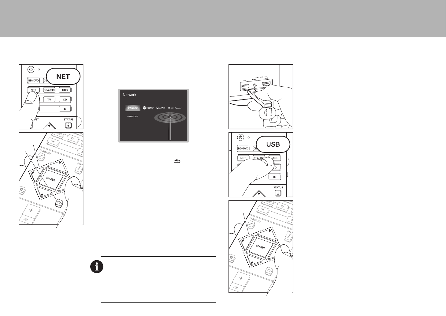
1. Switch the input on the TV to that assigned to the unit.
2. Press NET to display the network service list screen.
3. Select the item with the cursors of the remote controller
and press ENTER to confirm your selection (a). To
return to the previous screen, press (b).
Internet Radio
When this unit is connected to a network, you can listen to
TuneIn or other preregistered Internet radio services. After
selecting the desired service, follow the on-screen
instructions, using the cursors to select radio stations and
programs, then press ENTER to play. Play starts when
100% is displayed for buffering.
Music Server
You can play music files stored on home-network
compliant PCs or NAS devices connected to the same
network as this unit. Select the server with the cursors,
select the desired music file and press ENTER to start
playback. Play starts when 100% is displayed for buffering.
Notes:
0 Network services become selectable after the network
starts up even if they cannot be selected first.
0 Functionality may be introduced by firmware updates and
service providers may cease services, meaning that some
network services and content may become unavailable in
the future. Furthermore, available services may vary
depending on your area of residence.
a
b
USB
Play music files on a USB storage device.
0 Operation cannot be guaranteed for all USB storage
devices.
1. Plug your USB storage device with the music files into
the USB port on the front of the unit.
2. Press USB on the remote controller.
3. Select the desired folder or music file with the cursors of
the remote controller and press ENTER to confirm and
start playback (a).
0 This unit can use USB storage devices that comply with
the USB mass storage device class standard. The unit
is also compatible with USB storage devices using the
FAT16 or FAT32 file system formats.
a
SN29402194_VSX-301_BAS_En.book 22 ページ 2016年1月6日 水曜日 午前12時5分
En
23
> Before start > Hookup > Setup > Playback >Part Names
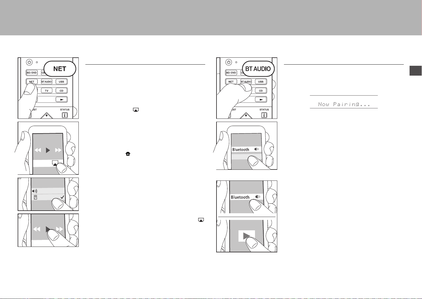
AirPlay
You can wirelessly enjoy the music files on an iPhone
®
,
iPod touch
®
, or iPad
®
connected to the same access point
as this unit.
0 Update the OS version on your iOS device to the latest
version.
1. Connect the iOS device to the access point.
2. Press NET.
3. Tap the AirPlay icon in the control center of the iOS
device and select this unit from the list of devices
displayed, and tap "Done".
4. Play the music files on the iOS device.
0 The default status is for the Network Standby feature to
be on, so when you do steps 3 and 4 above, this unit
automatically comes on and input switches to "NET". To
reduce the amount of power consumed in standby
mode, press the button on the remote controller,
then in the Home displayed set "System Setup" –
"Hardware" – "Power Management" – "Network
Standby" to "Off".
0 Due to the characteristics of AirPlay wireless
technology, the sound produced on this unit may slightly
be behind the sound played on the AirPlay-enabled
device.
You can also play back music files on the computer with
iTunes (Ver. 10.2 or later). Before operation, make sure
this unit and the PC are connected to the same network,
then press NET on this unit. Next, click the AirPlay icon
in iTunes, select this unit from the list of devices displayed,
and start play of a music file.
VSX-XXXXX
iPhone
BLUETOOTH
®
Playback
Pairing
1. When you press BT AUDIO on the remote controller,
"Now Pairing..." is displayed on this unit's display, and
the pairing mode is enabled.
2. Enable (turn on) the BLUETOOTH function of the
BLUETOOTH enabled device, then select this unit from
amongst the devices displayed.
If a password is requested, enter "0000".
0 To connect another BLUETOOTH enabled device, press
and hold BT AUDIO until "Now Pairing..." is displayed,
then perform step 2 above. This unit can store the data
of up to 8 paired devices.
0 The coverage area is 48 feet (15 meters). Note that
connection is not always guaranteed with all
BLUETOOTH enabled devices.
Playing Back
1. When the unit is on, connect the BLUETOOTH enabled
device.
2. The input selector of this unit will be automatically
switched to "BLUETOOTH".
3. Play music. Increase the volume of the BLUETOOTH
enabled device to an appropriate level.
0 Due to the characteristics of BLUETOOTH wireless
technology, the sound produced on this unit may slightly
be behind the sound played on the BLUETOOTH
enabled device.
VSX-XXXXX
SN29402194_VSX-301_BAS_En.book 23 ページ 2016年1月6日 水曜日 午前12時5分
24
> Before start > Hookup > Setup > Playback >Part Names
Others
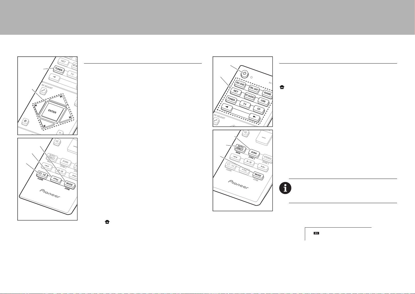
Listening To the Radio
1. Press TUNER (a) on the remote controller repeatedly to
select either "AM" or "FM" on the display.
2. Press MODE (c) on the remote controller, so that the
"TunMode: Auto" is displayed on the display.
3. When you press the / cursor (b) buttons on the
remote controller, automatic tuning starts, and searching
stops when a station is found. When tuned into a radio
station, the "TUNED" indicator on the display lights.
You can preset up to 40 stations.
1. Tune into the AM/FM radio station you want to register.
2. Press +Fav (d) on the remote controller so that the
preset number on the display flashes.
3. While the preset number is flashing (about 8 seconds),
repeatedly press the / cursor (b) buttons on the
remote controller to select a number between 1 and 40.
4. Press +Fav (d) again on the remote controller to register
the station. When registered, the preset number stops
flashing. To select a preset radio station, press the /
cursor (b) buttons on the remote controller.
0 To delete a preset station, press the / cursor (b)
buttons on the remote controller to select the preset
number you want to delete, press +Fav (d) on the
remote controller and then press CLEAR (e) while the
preset number is flashing. When deleted, the number on
the display goes off.
Frequency step setting
Press the button on the remote controller to select
"System Setup" – "Miscellaneous" – "Tuner" – "AM/FM
Frequency Step" and select the frequency step for your
area. Note that when this setting is changed, all radio
presets are deleted.
c
d
e
a
b
Multi-zone
If you haven't made the Multi Zone settings (
P20) in
Initial Setup, change the settings according to the audio
output method to the separate room (ZONE 2). Press the
button on the remote controller and make the settings
in System Setup accessed from the Home screen that is
displayed. If you have connected speakers in a separate
room with speaker cable, select "Zone 2" in "System
Setup" − "Speaker" − "Configuration" − "Zone Speaker".
If you have connected a power amplifier in a separate
room with an analog audio cable, then set "System Setup"
− "Multi Zone" − "Zone 2" − "Output Level" to "Variable"
if you want to be able to adjust the volume on this unit.
Play
1. While holding down MODE (a) on the remote controller,
press ZONE 2 (b) for 3 or more seconds until the remote
indicator blinks twice.
0 The remote controller switches to the mode for
controlling ZONE 2.
2. Point the remote controller at the main unit and press Í
(d).
"Z2" lights on the main unit display.
3. Press the input selector button (e) of the input to be
played in the separate room. On the main unit, after
pressing ZONE 2-CONTROL, within 8 seconds turn the
input selector dial to select the input to be played in the
separate room.
0 You can only select the same inputs for the main
room and separate room with the "NET" or
To return the remote controller to main room control
mode: While holding down MODE (a) on the remote
controller, press MAIN (c) for 3 seconds or more until the
remote indicator flashes once.
a
b
c
d
e
SN29402194_VSX-301_BAS_En.book 24 ページ 2016年1月6日 水曜日 午前12時5分
En
25
> Before start > Hookup > Setup > Playback >Part Names
"BLUETOOTH", or "USB" input selector. If you have
"NET" selected in the main room and then select
"USB" in the separate room, the main room also
switches to "USB". You cannot select different stations
for the main room and separate room with the AM/FM
radio.
4. To adjust the volume on this unit, adjust with VOL+/– on
the remote controller. To control on the main unit, press
ZONE 2-CONTROL and adjust with the MASTER
VOLUME control within 8 seconds.
0 If ZONE 2 is on, power consumption during standby
becomes larger than normal.
To turn off the function
Press Í while in the mode for controlling ZONE 2 on the
remote controller. Alternatively press ZONE 2-ON/OFF on
the main unit.
Playing in ZONE 2 only
If you turn the unit to standby during multi-zone playback,
the Z2 indicator is dimmed and the playback mode is
switched to playback in a separate room only. Setting
ZONE 2 to on while this unit is in standby will also switch
the playback mode to the same setting.
AV Adjust
By pressing on the remote controller during play, you
can adjust frequently used settings, such as the switching
the speakers and adjusting sound quality, using on-screen
menus. Select the item with the cursors of the remote
controller and press ENTER to confirm your selection. To
return to the previous screen, press .
"Tone": It is possible to enhance or moderate the bass and
treble of front speakers. You can adjust the sound quality of
the connected power amplifier when you turn ZONE 2 on.
"Other": Enables you to make a variety of settings.
0 "Sound Delay": If the video is behind the audio, you can
delay the audio to offset the gap.
0 "Sound Retriever": Improve the quality of compressed
audio.
0 "Speakers": You can switch the output on the surround
back speakers and height speakers and switch the
output for speakers A/B.
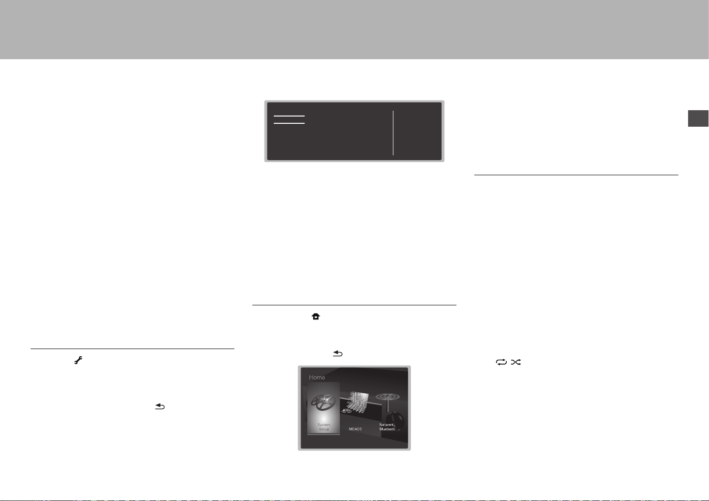
Home
When you press on the remote controller, the Home is
displayed and you can make settings in the various menus.
Select the item with the cursors of the remote controller and
press ENTER to confirm your selection. To return to the
previous screen, press .
"System Setup": Advanced settings to provide you with an
even better experience.
"MCACC": Setup the speakers automatically or make
desired changes to the equalizer.
"Network/Bluetooth": Make Wi-Fi connection settings or
settings related to BLUETOOTH.
When the unit is operating erratically
(Resetting this unit)
Restarting the unit may help it operate more smoothly. To
restart the unit, turn it to standby, and then press
Í STANDBY/ON on the main unit for at least 5 seconds.
(The unit’s settings will be maintained.) If there is no
improvement even after the unit is restarted, try
disconnecting and reconnecting the power cords of the unit
and connected equipment. When there is still no
improvement, resetting the unit to the status at the time of
shipment may solve the problem. If you reset the unit
status, your preferences will be reset to the defaults. Note
them down before the operation below.
How to reset the unit
1. While holding down AUTO/DIRECT on the main unit,
press Í STANDBY/ON on the main unit.
2. "Clear" appears on the display and the unit returns to
standby. Do not unplug the power cord until "Clear"
disappears from the display.
To reset the remote controller, while holding down MODE,
press until the remote indicator flash twice (about
3 seconds).
AV Adjust
Tone
Level
MCACC
Other
Bass
Treble
BD/DVD
SN29402194_VSX-301_BAS_En.book 25 ページ 2016年1月6日 水曜日 午前12時5分
26
> Before start > Hookup > Setup > Playback >Part Names
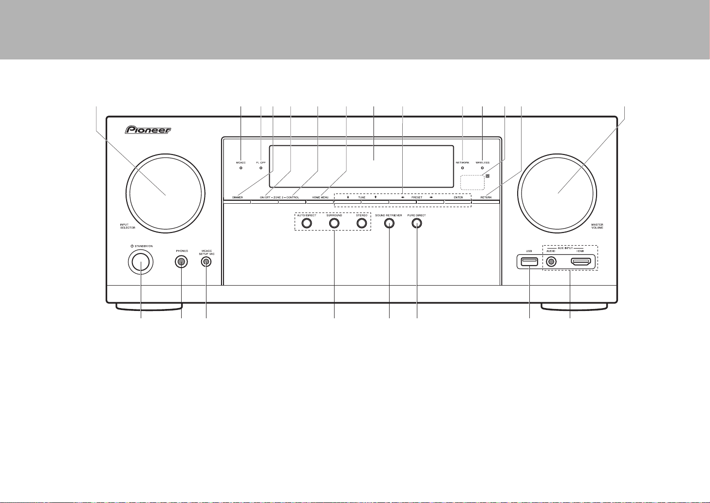
Front Panel
1. INPUT SELECTOR dial: Switch the input to be played.
2. MCACC indicator: This lights when you have enabled the
speaker calibration made with MCACC.
3. FL OFF indicator: This lights when you have pressed
DIMMER repeatedly to turn the display off.
4. DIMMER button: Switches the brightness of the display.
5. ZONE 2-ON/OFF button: Switches the multi-zone
function on/off.
6. ZONE 2-CONTROL button: Controls the multi-zone
function.
7. HOME MENU button: Displays the Home.
8. Display (
P28)
9. Cursor buttons (TUNE / PRESET button) and
ENTER button: Select the item with the cursors and
press ENTER to confirm your selection. When using the
TUNER, select the frequency with TUNE, or select
preset stations with PRESET.
10.
NETWORK indicator: When the power of the unit is on,
this lights when "NET" is selected with the input selector
and the unit is connected to the network. If the unit is in
standby mode, this lights when functions such as HDMI
CEC and network standby are enabled. It does not light
when ZONE 2 is on, however.
11.
WIRELESS indicator: Lights when the unit is connected
to the wireless network.
12.
Remote control sensor
13.
RETURN button: Returns the display to the previous
state.
14.
MASTER VOLUME: Allows you to adjust the volume.
15.
Í STANDBY/ON button: Turns the unit on or into
standby mode.
16.
PHONES jack: Stereo headphones with a standard plug
(1/4 inch or ø6.3 mm) are connected.
17.
MCACC SETUP MIC jack: The supplied speaker setup
microphone is connected.
18.
Listening mode button: Select the listening mode.
19.
SOUND RETRIEVER button: Turns on/off the Sound
Retriever function that provides better sound quality for
compressed audio.
20.
PURE DIRECT button: Swithes to the Pure Direct mode.
21.
USB port: A USB storage device is connected so that
music files stored in it can be played. You can also
supply power (5V/1A) to USB devices with a USB cable.
22.
AUX INPUT AUDIO/HDMI jack: A video camera or such
other device is connected.
12 106121314115798
16
15
22
18 2117
43
19 20
SN29402194_VSX-301_BAS_En.book 26 ページ 2016年1月6日 水曜日 午前12時5分
En
27
> Before start > Hookup > Setup > Playback >Part Names
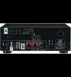
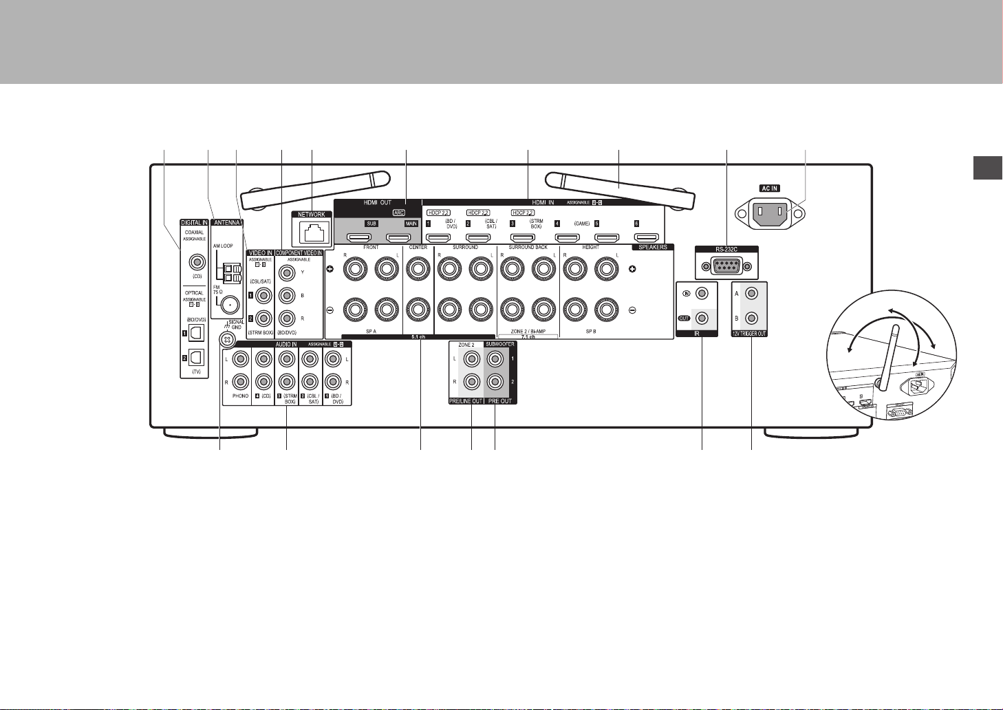
Rear Panel
1. DIGITAL IN OPTICAL/COAXIAL jacks: Input TV or AV
component digital audio signals with a digital optical
cable or digital coaxial cable.
2. ANTENNA AM LOOP/FM 75Ω terminal: The supplied
antennas are connected.
3. VIDEO IN jacks: Input the AV component video signals
with an analog video cable.
4. COMPONENT VIDEO IN jacks: Input the AV component
video signals with a component video cable.
5. NETWORK port: Connect to the network with an
Ethernet cable.
6. HDMI OUT jacks: Transmit video signals and audio
signals with a HDMI cable connected to a monitor such
as a TV or projector.
7. HDMI IN jacks: Transmit video signals and audio signals
with a HDMI cable connected to an AV component.
8. Wireless antenna: Used for Wi-Fi connection or when
using a BLUETOOTH enabled device. Adjust their
angles according to the connection status.
9. RS-232C port: For connection to the home control
system.
10.AC IN: The supplied power cord is connected.
11.SIGNAL GND terminal: The ground wire of the turntable
is connected.
12.
AUDIO IN jacks: Input AV component audio signal with
an analog audio cable.
13.
SPEAKERS terminals: Connect speakers with speaker
cables.
14.
ZONE 2 PRE/LINE OUT jack: Output audio signals with
an analog audio cable to a pre-main amplifier or a
powered amplifier in a separate room (ZONE 2).
15.
SUBWOOFER PRE OUT jack: Connect a powered
subwoofer with a subwoofer cable. Up to two powered
subwoofers can be connected. The same signal is output
from each of the SUBWOOFER PRE OUT jacks.
16.
IR IN/OUT port: Allows you to connect a multiroom
remote control kit.
17.
12V TRIGGER OUT A/B jacks: Allows you to connect a
device with 12V trigger input jack to enable link operation
between the device and the unit.
1211 1413
109
8
8
1
23 5 764
15 16 17
180°
90°
SN29402194_VSX-301_BAS_En.book 27 ページ 2016年1月6日 水曜日 午前12時5分
28
> Before start > Hookup > Setup > Playback >Part Names
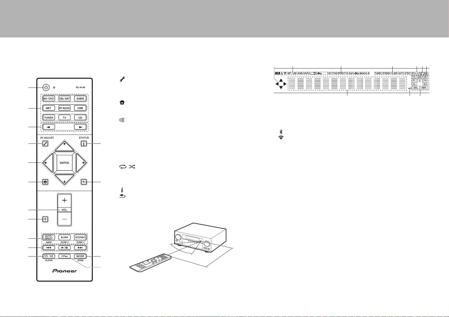
Remote Controller
1. Í button: Turns the unit on or into standby mode.
2. Input selector buttons: Switches the input to be played.
3. 21 button: Select the input to be played.
4. (AV ADJUST) button: You can perform common settings on
the TV screen.
5. Cursor buttons and ENTER button: Select the item with the
cursors and press ENTER to confirm your selection.
6. button: Displays the Home.
7. Volume buttons: Allows you to adjust the volume. This button
also cancels the muting.
8. button: Temporarily mutes audio. Press again to cancel
muting.
9. LISTENING MODE buttons: Allows you to select the listening
mode.
MAIN/ZONE 2 buttons: Controls the multi-zone function.
(The ZONE 3 button is not used with this unit.)
10.
Play button: Used for play operations when playing Music Server
or USB.
11.
button: Used for repeat or random play operations when
playing Music Server or USB.
CLEAR button: Deletes all characters you have entered when
entering text on the TV screen.
12.
(STATUS) button: Switches the information on the display.
13.
button: Returns the display to the previous state.
14.
MODE button: Switches tuning to a station between automatic
tuning and manual tuning.
15.
+Fav button: Registers a radio station.
9
10
1
2
4
3
6
8
7
5
11
12
14
13
15
30°
30°
Approx.5 m
Display
1. This may light when performing operations with the "NET", "USB"
input selector.
2. Lights in the following conditions.
Z2: When ZONE 2 is on.
: When connected by BLUETOOTH.
: When connected by Wi-Fi.
NET: When "NET" is selected with the input selector and the unit is
connected to the network. It will flash if the connection to the network
is not correct.
USB: When "USB" is selected with the input selector and the unit is
connected by USB and the USB device is selected. Flashes if the
USB is not properly connected.
HDMI: When HDMI signals are input and the HDMI input is selected.
DIGITAL: When digital signals are input and the digital input is
selected.
3. Lights according to the type of input digital audio signals and the
listening mode.
4. Lights in the following conditions.
TUNED: Receiving AM/FM radio.
STEREO: Receiving FM stereo.
SLEEP: When the sleep timer is set.
AUTO STBY: Auto Standby is on.
5. The currently selected speaker system lights.
6. Lights when headphones are connected.
7. Flashes when muting is on.
8. Displays various information of the input signals.
9. Lights when adjusting the volume.
10.
Speaker/Channel display: Displays the output channel that
corresponds to the selected listening mode.
14
8
2 3
9
65 7
10
SN29402194_VSX-301_BAS_En.book 28 ページ 2016年1月6日 水曜日 午前12時5分
29
En
License and Trademark Information
Manufactured under license from Dolby Laboratories. Dolby, Dolby Atmos,
Dolby Surround and the double-D symbol are trademarks of Dolby
Laboratories.
For DTS patents, see http://patents.dts.com. Manufactured under license from
DTS, Inc. DTS, the Symbol, DTS in combination with the Symbol, the DTS-HD
logo, and DTS-HD Master Audio are registered trademarks or trademarks of
DTS, Inc. in the United States and/or other countries. © DTS, Inc. All Rights
Reserved.
The terms HDMI and HDMI High-Definition Multimedia Interface, and the HDMI
Logo are trademarks or registered trademarks of HDMI Licensing LLC in the
United States and other countries.
The Wi-Fi CERTIFIED Logo is a certification mark of the Wi-Fi Alliance
®
.
AirPlay, iPad, iPhone, and iPod touch are trademarks of Apple Inc., registered
in the U.S. and other countries.
iPad Air and iPad mini are trademarks of Apple Inc.
“Made for iPod”, “Made for iPhone” and “Made for iPad” mean that an electronic
accessory has been designed to connect specifically to iPod, iPhone, or iPad,
respectively, and has been certified by the developer to meet Apple
performance standards. Apple is not responsible for the operation of this device
or its compliance with safety and regulatory standards.
Please note that the use of this accessory with iPod, iPhone or iPad may affect
wireless performance.
AirPlay works with iPhone, iPad, and iPod touch with iOS 4.3.3 or later, Mac
with OS X Mountain Lion or later, and PC with iTunes 10.2.2 or later.
Apple, Apple TV and Safari are trademarks of Apple Inc., registered in the U.S.
and other countries.
The BLUETOOTH
®
word mark and logos are registered trademarks owned by
Bluetooth SIG, Inc. and any use of such marks by Onkyo Corporation is under
license. Other trademarks and trade names are those of their respective
owners.
Onkyo Corporation does not guarantee BLUETOOTH compatibility between the
AV receiver and all BLUETOOTH enabled devices.
For compatibility between the AV receiver and another device with
BLUETOOTH technology, consult the device’s documentation and dealer. In
some countries, there may be restrictions on using BLUETOOTH devices.
Check with your local authorities.
Onkyo Corporation ne garantit pas la compatibilité BLUETOOTH entre l'ampli-
tuner AV et tous les appareils compatibles BLUETOOTH.
Pour assurer la compatibilité entre l'ampli-tuner AV et un autre périphérique à
technologie BLUETOOTH, consultez la documentation de l'appareil et le
vendeur. Dans certains pays, il peut exister des restrictions sur l'utilisation
d'appareils BLUETOOTH. Vérifiez auprès des autorités locales.
Onkyo Corporation no garantiza la compatibilidad BLUETOOTH entre el receptor
de AV y todos los dispositivos con tecnología BLUETOOTH.
Para obtener información sobre la compatibilidad entre el receptor de AV y otro
dispositivo con tecnología BLUETOOTH, consulte al distribuidor y la documentación
del dispositivo. En algunos países, es posible que el uso de dispositivos
BLUETOOTH esté restringido. Consulte con las autoridades locales.
PANDORA, the PANDORA logo, and the Pandora trade dress are trademarks
or registered trademarks of Pandora Media, Inc. Used with permission.
Google Cast and the Google Cast badge are trademarks of Google inc.
The product with this logo is conformed to Hi-Res Audio standard defined by
Japan Audio Society. This logo is used under license from Japan Audio Society.
This product is protected by certain intellectual property rights of Microsoft. Use
or distribution of such technology outside of this product is prohibited without a
license from Microsoft.
Windows and the Windows logo are trademarks of the Microsoft group of
companies.
QR Code is a registered trademark of DENSO WAVE INCORPORATED.
“x.v.Color” and “x.v.Color” logo are trademarks of Sony Corporation.
DSD and the Direct Stream Digital logo are trademarks of Sony Corporation.
MPEG Layer-3 audio coding technology licensed from Fraunhofer IIS and
Thomson.
“All other trademarks are the property of their respective owners.”
“Toutes les autres marques commerciales sont la propriété de leurs détenteurs
respectifs.”
“El resto de marcas comerciales son propiedad de sus respectivos propietarios”.
DISCLAIMER
Through this device you are able to link to other services or websites which are
not under the control of any company which has designed, manufactured or
distributed/have distributed this device, and its affiliates (collectively,
“Company”). We have no control over the nature, content and availability of
those services. The inclusion of any links does not necessarily imply a
recommendation or endorse the views expressed within them.
All information, content and services available through this device belong to
third parties and are protected by copyright, patent, trademark and/or other
intellectual property laws of applicable countries.
The information, content and services provided through this device are for your
personal, noncommercial use only. Any information, content or services may
not be used in any manner other than previously approved by the appropriate
content owner or service provider.
You may not modify, copy, republish, translate, exploit, create derivative works,
upload, post, transmit, sell or distribute in any manner any information, content
or services available through this device, unless expressly permitted by the
appropriate copyright, patent, trademark and/or other intellectual property
owner, including, without limitation, content owner or service provider.
THE CONTENT AND SERVICES AVAILABLE THROUGH THIS DEVICE ARE
PROVIDED “AS IS”.
COMPANY DOES NOT WARRANT INFORMATION, CONTENT OR
SERVICES SO PROVIDED, EITHER EXPRESSLY OR IMPLIEDLY, FOR ANY
PURPOSE.
COMPANY EXPRESSLY DISCLAIMS ANY WARRANTIES, EXPRESS OR
IMPLIED, INCLUDING BUT NOT LIMITED TO, WARRANTIES OF TITLE,
NON-INFRINGEMENT, MERCHANTABILITY OR FITNESS FOR A
PARTICULAR PURPOSE.
Company makes no representation or warranty of any kind, express or implied,
about the completeness, accuracy, validity, legality, reliability, suitability or
availability with respect to the information, content or services available through
this device. Company shall not be liable, whether in contract or tort, including
negligence and strict liability, for any direct, indirect, special, incidental or
consequential damages or any other damages arising out of, or in connection
with, any information contained in, or as a result of the use of any content or
service by you or any third party, even if Company has been advised of the
possibility of such damages, nor shall Company be liable for any third party
claims against users of this device or any third party.
In no event shall Company be responsible nor liable for, without limiting the
generality of the foregoing, any interruption or suspension of any information,
content or service available through this device. Company is neither
responsible nor liable for customer service related to the information, content
and services available through this device. Any question or request for service
relating to the information, content or services should be made directly to the
appropriate content owners and services providers.
®
SN29402194_VSX-301_BAS_En.book 29 ページ 2016年1月6日 水曜日 午前12時5分

30
SN29402194_VSX-301_BAS_En.book 30 ページ 2016年1月6日 水曜日 午前12時5分

Fr
Mode d'Emploi
Base
Raccordement
Étape 1 : Choisissez la disposition d’enceinte ........................ 3
Étape 2 : Raccordez les enceintes ......................................... 9
Étape 3 : Raccordez le téléviseur ......................................... 12
Étape 4 : Raccordez les appareils AV .................................. 14
Étape 5 : Raccordement d'autres câbles .............................. 18
Configuration
Étape 6 : Mise sous tension & Configuration initiale ............ 19
Configuration HDMI .............................................................. 20
Lecture
Lecture de base .................................................................... 21
Fonctions réseau .................................................................. 22
Autres ................................................................................... 24
Nom des pièces
Panneau frontal .................................................................... 26
Panneau arrière .................................................................... 27
Télécommande ..................................................................... 28
L'afficheur ............................................................................. 28
Ce mode d'emploi contient les informations nécessaires pour la mise en route
ainsi que les instructions concernant les commandes les plus fréquemment
utilisées. Le "Mode d'emploi avancé" est disponible sur Internet et contient des
détails sur les fonctionnalités de lecture/les modes d'écoute/les descriptions
des paramètres, les spécifications, et le dépannage. Le mode d'emploi avancé
a été conçu dans un format qui le rend facile à lire sur un ordinateur ou un
smartphone.
http://www.pioneer-audiovisual.com/manual/vsxlx301/adv/fr.html
Mode d'emploi avancé, cliquez ici
VSX-LX301
> Avant de démarrer > Raccordement > Configuration > Lecture > Nom des pièces
Récepteur AV
SN29402194_VSX-301_BAS_Fr.book 1 ページ 2016年1月6日 水曜日 午前12時10分
2
> Avant de démarrer > Raccordement > Configuration > Lecture > Nom des pièces
Ce que contient la boîte
1. Appareil principal 2. Télécommande (RC-914R)
×1, Piles (AAA/R03) ×2
3. Antenne FM d'intérieur ×1 4. Antenne cadre AM ×1 5. Microphone de configuration d'enceinte ×1
6. Cordon d'alimentation ×1
Caractéristiques principales
Pour lire, sélectionnez la source à l'aide du sélecteur d'entrée. Vous pouvez raccorder un kit d'enceintes 7.1 à cet
appareil, avec 7 canaux à 170 W (6 ohms, 1 kHz, 0.9%DHT) chacun plus une prise Pre out pour caisson de
basse sous tension.
$
Prend en charge la lecture au format Dolby Atmos qui fournit un positionnement sonore à 360e
$
La prise HDMI prend en charge l'entrée et la sortie vidéo 4K. Prises IN1 à 3 et OUT MAIN/SUB support
HDCP2.2
$
Fonctionnalité HDMI CEC : Caractéristiques de contrôle telles que la liaison de commutation d'entrée avec le
sélecteur d'entrée et les lecteurs en conformité avec la norme CEC, le changement de la sortie audio et du
volume à l'aide de la télécommande d'un téléviseur conforme CEC et le passage en veille automatique de cet
appareil lorsque le téléviseur est éteint
$
HDMI Standby Through : Les signaux vidéo et audio provenant des appareils AV peuvent être transmis vers le
téléviseur même si cet appareil est en veille
$
ARC : Le raccordement avec un téléviseur compatible ARC ne nécessite qu'un seul câble HDMI
$
Initial Setup facile grâce au guide et à l'affichage à l'écran (OSD) montrant les commandes sur le téléviseur
$
Webradio et Airplay via un réseau local (LAN) filaire ou Wi-Fi (LAN sans fil) et des fonctionnalités du réseau
comme Music Server qui permettent la lecture des fichier musicales de l'ordinateur, la lecture de l'USB, et en
plus autres fonctionnalités de lecture comme la radio AM/FM et BLUETOOTH
®
$
Les formats de lecture pris en charge par Music Server et USB comprennent les fichiers WAV, FLAC et la
source DSD haute résolution
$
Connexion multi-zone qui vous permet de lire dans la pièce principale et d’écouter dans une autre pièce (ZONE 2)
$
Vous pouvez raccorder un système d’enceinte B
$
Équipé d’un port RS-232C, d’une prise IR IN/OUT, et de prises 12V TRIGGER OUT A/B
$
Nous prévoyons de fournir une assistance pour le format audio DTS:X par le biais d'une mise à jour du
micrologiciel de cet appareil. Consultez notre page d'accueil pour plus d'informations.
MISE EN GARDE : Raccordez des enceintes ayant une valeur d'impédance comprise entre 6 Ω et 16 Ω.
Le cordon d'alimentation devra être branché uniquement lorsque tous les autres raccordements seront
effectués.
0 Nous n'acceptons en aucun cas la responsabilité pour des dommages résultant d'une connexion à des
équipements fabriqués par d'autres sociétés.
1
2
56
34
SN29402194_VSX-301_BAS_Fr.book 2 ページ 2016年1月6日 水曜日 午前12時10分

3
> Avant de démarrer > Raccordement > Configuration > Lecture > Nom des pièces
Fr
Étape 1 : Choisissez la disposition d’enceinte
12
Enceintes avant
3
Enceinte centrale
45
Enceintes surround
6
Caisson de basse sous tension
Pour un système 5.1
Il s'agit d'un système 5.1 qui est le système surround de base.
Les enceintes avant reproduisent le son stéréo avant et l'enceinte centrale
reproduit le son central comme les dialogues et les voix. Les enceintes
surround produisent un champ sonore arrière. Le caisson de basse sous
tension reproduit les sons graves et crée un riche champ sonore. Les
enceintes avant devront être positionnées à hauteur d'oreille, tandis que les
enceintes surround devront être positionnées juste au-dessus de la hauteur
d'oreille. L'enceinte centrale devra faire face à la position d'écoute. Placez le
caisson de basse sous tension vers l'avant. En le plaçant entre l'enceinte
centrale et une enceinte avant vous obtiendrez un son naturel même durant la
lecture de musique.
0 Les enceintes avant, l'enceinte centrale et les enceintes surround sont
comptabilisées comme 5 voies, et le caisson de basse sous tension comme
0.1 d'une voie, ce qui donne son nom au système 5.1.
Allez à "Raccordement" (
P9)
* 1: 22e à 30e, * 2 : 120e
Systeme d'Enceinte B:
Sur un Système 5.1, vous pouvez
raccorder un ou plusieurs ensembles
d’enceintes avant à utiliser comme
Système d’Enceinte B. Dans cet état, le
Système 5.1 devient le Système d’Enceinte
A et vous pouvez basculer le même son à
reproduire entre A, B, ou A+B. Notez que le
son n’est pas réliqué par enceinte B
lorsque Zone Speaker est utilisé (
P17).
Allez à "Raccordement" (
P9)
*
1
*
2
SN29402194_VSX-301_BAS_Fr.book 3 ページ 2016年1月6日 水曜日 午前12時10分
4
> Avant de démarrer > Raccordement > Configuration > Lecture > Nom des pièces
16
(
P3)
78
Enceintes surround arrière
Pour un système 7.1 (avec enceintes
surround arrière)
Il s'agit d'un système constitué d'enceintes surround arrière ajoutées au système 5.1 de base. Le
raccordement des enceintes surround arrière améliore la sensation d'immersion et de connectivité du
son créée par le champ sonore arrière qui en devient plus réaliste. Vous pouvez sélectionner le mode
d'écoute Dolby Atmos, qui réalise le son surround 3D le plus moderne, lorsque le format d’entrée est
Dolby Atmos. Avec des formats autres que Dolby Atmos, vous pouvez encore créer un champ sonore
en reproduisant le son depuis les enceintes surround arrière lorsque vous sélectionner le mode
d'écoute Dolby Surround. La position optimale des enceintes surround arrière est à hauteur d'oreilles.
Placez les enceintes surround légèrement plus en avant que vous le feriez avec le système 5.1.
0 Si vous incluez les enceintes surround arrière dans la configuration, les
enceintes surround sont nécessaires.
Allez à "Raccordement" (
P9)
* 1: 22e à 30e, * 2 : 90e à 110e, * 3 : 135e à 150e
Systeme d'Enceinte B:
Sur un Système 7.1(avec Enceintes surround
arrière), vous pouvez raccorder un ou
plusieurs ensembles d’enceintes avant à
utiliser comme Système d’Enceinte B. Dans
cet état, le Système 7.1 devient le Système
d’Enceinte A et vous pouvez basculer le même
son à reproduire entre A, B, ou A+B. Notez
que le son n’est pas restitué par l’enceinte
surround arrière lorsque A+B est sélectionné.
Notez que le son n’est pas réliqué par enceinte
B lorsque Zone Speaker est utilisé (
P17).
Allez à "Raccordement" (
P9)
*
2
*
3
*
1
SN29402194_VSX-301_BAS_Fr.book 4 ページ 2016年1月6日 水曜日 午前12時10分
5
> Avant de démarrer > Raccordement > Configuration > Lecture > Nom des pièces
Fr
3´ (0.9 m)
or more
16
(
P3)
9:
Enceintes en hauteur
Choisissez une des options suivantes :
$
$
Enceintes en hauteur avant
Enceintes en hauteur arrière
Pour un système 7.1
(avec enceintes en hauteur-A)
Il s'agit du système 5.1 de base avec, en plus, des enceintes en hauteur, soit
les enceintes en hauteur avant soit les enceintes en hauteur arrière.
Choisissez quelles enceintes configurer en fonction de l'environnement de la
pièce. Vous pouvez sélectionner le mode d'écoute Dolby Atmos (lecture au
format 5.1.2), qui réalise le son surround 3D le plus moderne y compris les
sons en hauteur lorsque le format d’entrée est Dolby Atmos. Avec des formats
autres que Dolby Atmos, vous pouvez encore créer un champ sonore en
restituant le son par les enceintes en hauteur lorsque vous sélectionnez le
mode d'écoute Dolby Surround. Les enceintes en hauteur avant ou les
enceintes en hauteur arrière devront être positionnées à au moins 0,9 m au-
dessus des enceintes avant. Les enceintes en hauteur avant devront être
positionnées directement au-dessus des enceintes avant et la distance entre
les enceintes en hauteur arrière devra correspondre à la distance entre les
enceintes avant. Les deux devront faire face à la position d'écoute.
Allez à "Raccordement" (
P10)
* 1: 22e à 30e, * 2 : 120e
*
1
*
2
SN29402194_VSX-301_BAS_Fr.book 5 ページ 2016年1月6日 水曜日 午前12時10分
6
> Avant de démarrer > Raccordement > Configuration > Lecture > Nom des pièces
16
(
P3)
9:
Enceintes en hauteur
Choisissez une des options suivantes :
$
$
$
Enceintes supérieures avant
Enceintes supérieures centrales
Enceintes supérieures arrière
Pour un système 7.1
(avec enceintes en hauteur-B)
Il s'agit du système 5.1 de base utilisant les enceintes pour plafond avec, par
exemple, en plus des enceintes en hauteur, soit les enceintes pour plafond
avant, soit les enceintes pour plafond centrales, soit les enceintes pour
plafond arrière. Vous pouvez sélectionner le mode d'écoute Dolby Atmos
(lecture au format 5.1.2), qui réalise le son surround 3D le plus moderne y
compris les sons en hauteur lorsque le format d’entrée est Dolby Atmos. Avec
des formats autres que Dolby Atmos, vous pouvez encore créer un champ
sonore en restituant le son par les enceintes en hauteur lorsque vous
sélectionnez le mode d'écoute Dolby Surround. Positionnez les enceintes
pour plafond avant devant la position d'écoute, les enceintes pour plafond
centrales directement au-dessus de la position d'écoute, et les enceintes pour
plafond arrière derrière la position d'écoute. La distance entre chaque paire
d'enceintes devra être la même que celle entre les deux enceintes avant.
0 Dolby Laboratories conseille le positionnement de ce type d'enceinte en
hauteur pour obtenir le meilleur effet Dolby Atmos.
Allez à "Raccordement" (
P10)
* 1: 30e à 55e, * 2: 65e à 100e, * 3: 125e à 150e
*
1
*
2
*
3
SN29402194_VSX-301_BAS_Fr.book 6 ページ 2016年1月6日 水曜日 午前12時10分
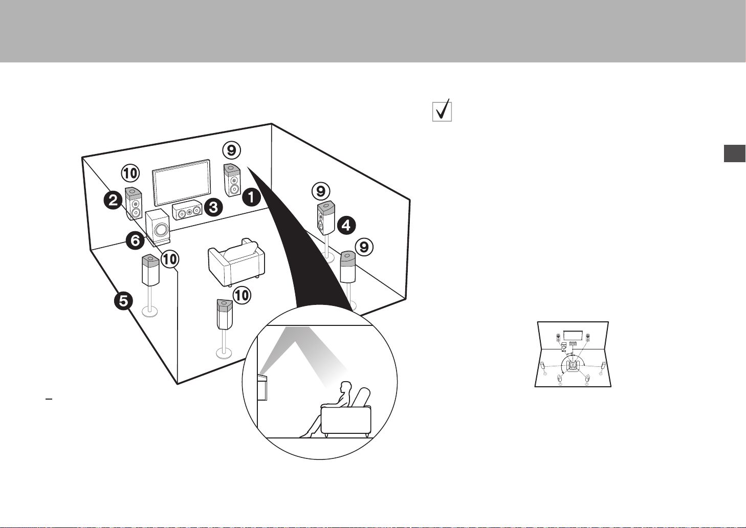
7
> Avant de démarrer > Raccordement > Configuration > Lecture > Nom des pièces
Fr
16
(
P3)
9:
Enceintes en hauteur
Choisissez une des options suivantes :
$
$
$
Enceintes activées Dolby (Avant)
Enceintes activées Dolby (Surround)
Enceintes activées Dolby (Surround arriere)
Pour un système 7.1
(avec enceintes en hauteur-C)
Il s'agit du système 5.1 de base utilisant, en plus des enceintes en hauteur, les
enceintes activées Dolby, soit les enceintes activées Dolby (avant) soit les
enceintes activées Dolby (surround) ou les enceintes activées Dolby
(surround arrière). Choisissez quelles enceintes configurer en fonction de
l'environnement de la pièce. Les enceintes activées Dolby sont des enceintes
spéciales conçues pour faire face au plafond afin que le son soit entendu
après avoir rebondi sur le plafond et semble provenir d’en haut. Vous pouvez
sélectionner le mode d'écoute Dolby Atmos (lecture au format 5.1.2), qui
réalise le son surround 3D le plus moderne y compris les sons en hauteur
lorsque le format d’entrée est Dolby Atmos. Avec des formats autres que
Dolby Atmos, vous pouvez encore créer un champ sonore en restituant le son
par les enceintes en hauteur lorsque vous sélectionnez le mode d'écoute
Dolby Surround. Placez-les sur les enceintes avant ou sur les enceintes
surround ou les enceintes surround arrière. S'il s'agit d'enceintes activées
Dolby intégrées, installez-les à la place des enceintes avant, des enceintes
surround ou des enceintes surround arrière.
Allez à "Raccordement" (
P10)
* 1: 22e à 30e, * 2 : 90e à 120e, * 3 : 135e à 150e
*
1
*
2
*
3
SN29402194_VSX-301_BAS_Fr.book 7 ページ 2016年1月6日 水曜日 午前12時10分

8
> Avant de démarrer > Raccordement > Configuration > Lecture > Nom des pièces
12
Enceintes avant (bi-amplification)
3
Enceinte centrale
45
Enceintes surround
6
Caisson de basse sous tension
Pour la bi-amplification des enceintes
Il est possible de raccorder des enceintes avant prenant en charge la bi-
amplification pour améliorer la qualité des gammes de graves et d'aiguës. Le
nombre maximum de voies disponibles avec ce raccordement est de 5.1 car
les enceintes de bi-amplification nécessitent un amplificateur pour les prises
des aigus et un pour les prises des graves. Les effets et positionnements des
enceintes sont les mêmes que pour une configuration 5.1 qui n'utilise pas
d'enceintes de bi-amplification.
Allez à "Raccordement" (
P11)
* 1: 22e à 30e, * 2: 120e
*
1
*
2
SN29402194_VSX-301_BAS_Fr.book 8 ページ 2016年1月6日 水曜日 午前12時10分
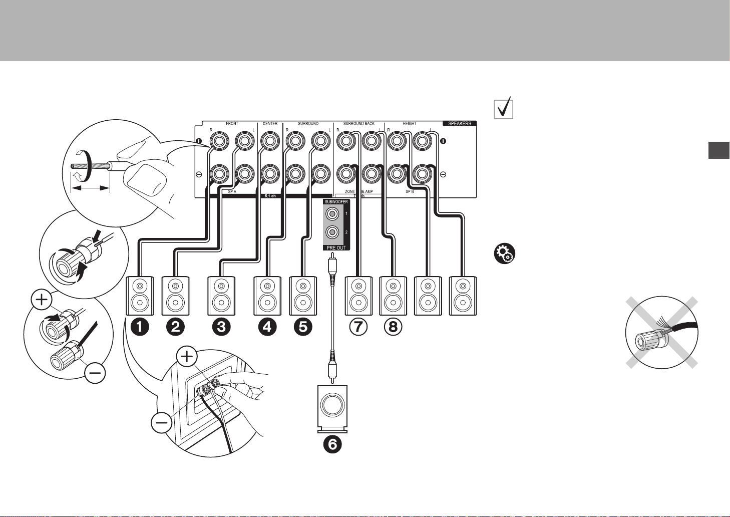
9
> Avant de démarrer > Raccordement > Configuration > Lecture > Nom des pièces
Fr
Étape 2 : Raccordez les enceintes
2
1
1/2˝
(12 mm)
Speaker B
1 Câble d'enceinte, 2 Câble du caisson de basse
dans le cas de :
Pages 3 à 4
Raccordez 123456 pour un système 5.1. Avec un
Système 7.1 (avec Enceintes arrière), raccordez aussi 7
et 8. Il est possible de raccorder jusqu'à deux caissons
de basse sous tension. Le même signal est reproduit par
chacune des prises SUBWOOFER. Avec ce
raccordement, vous pouvez raccorder un ou plusieurs
ensembles d’enceintes avant à utiliser comme Système
d’Enceinte B. Changez les Enceintes A/B avec le Réglage
AV (
P25). Notez que le son n’est pas répliqué par
l’enceinte surround arrière lorsque A+B est sélectionné.
Vérifiez que les fils dénudés des enceintes ne dépassent pas des
bornes d'enceinte lors du raccordement. Si les fils dénudés des
enceintes entrent en contact avec le panneau arrière ou si les fils
+ et – se touchent, le circuit de protection sera activé.
Configuration
0 Les réglages pour la configuration de l’enceinte
que vous avez raccordée doivent être faits dans "1.
MCACC automatique intégrale" (
P19) dans la
Initial Setup.
SN29402194_VSX-301_BAS_Fr.book 9 ページ 2016年1月6日 水曜日 午前12時10分
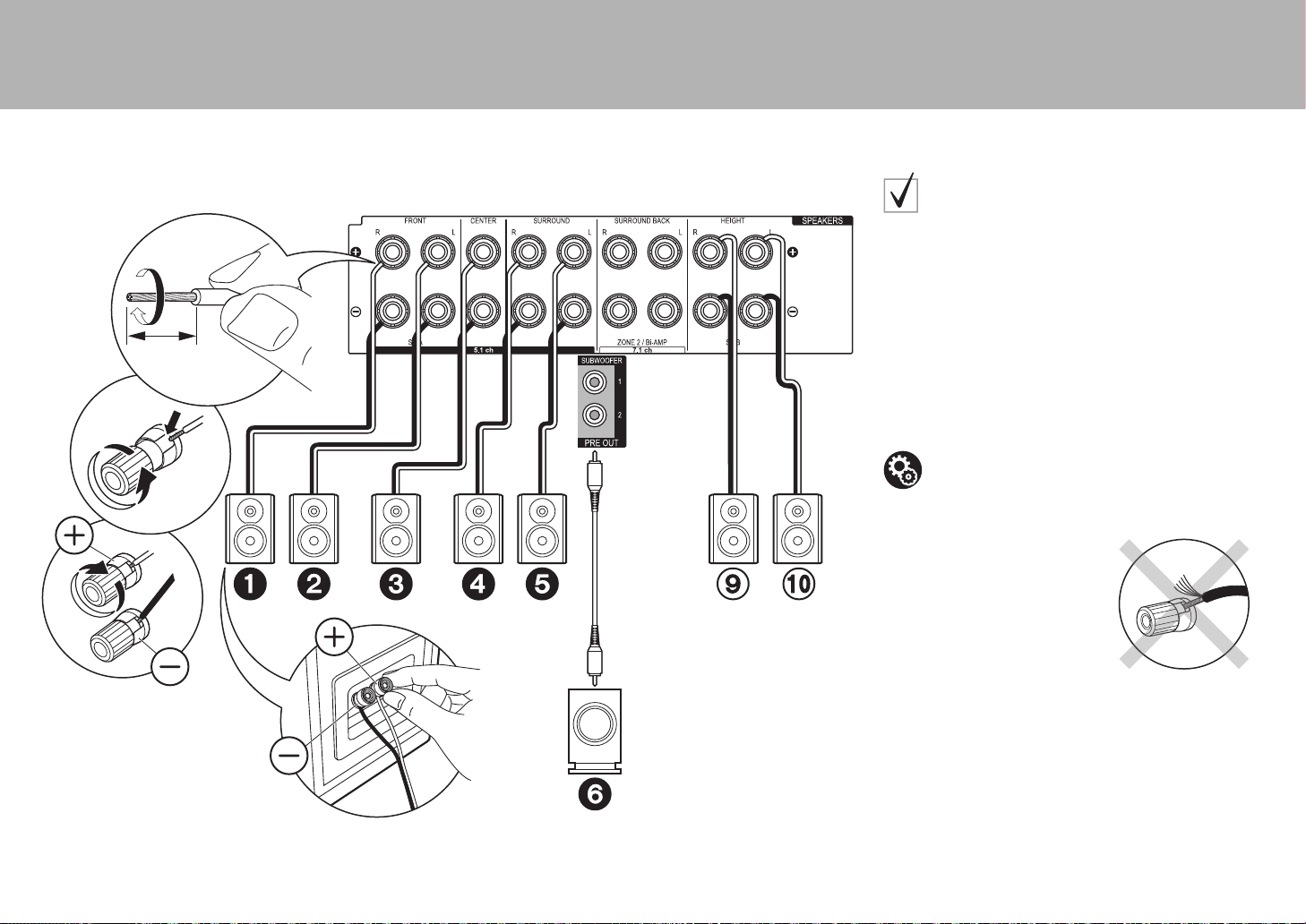
10
> Avant de démarrer > Raccordement > Configuration > Lecture > Nom des pièces
2
1
1/2˝
(12 mm)
1 Câble d'enceinte, 2 Câble du caisson de basse
dans le cas de :
Pages 5 à 7
Raccordez 1234569:. Il est possible de raccorder
jusqu'à deux caissons de basse sous tension. Le même
signal est reproduit par chacune des prises
SUBWOOFER.
0 En dehors de ces raccordements, vous pouvez aussi
raccorder les enceintes surround arrière 7 et 8.
Toutefois, vous pouvez reproduire le son d’un seul
ensemble de 78 ou 9: à la fois. Si les deux sont
raccordés, vous pouvez sélectionner à quelles
enceintes donner la priorité avec le Réglage AV
(
P25).
Vérifiez que les fils dénudés des enceintes ne dépassent pas des
bornes d'enceinte lors du raccordement. Si les fils dénudés des
enceintes entrent en contact avec le panneau arrière ou si les fils
+ et – se touchent, le circuit de protection sera activé.
Configuration
0 Les réglages pour la configuration de l’enceinte
que vous avez raccordée doivent être faits dans "1.
MCACC automatique intégrale" (
P19) dans la
Initial Setup.
SN29402194_VSX-301_BAS_Fr.book 10 ページ 2016年1月6日 水曜日 午前12時10分
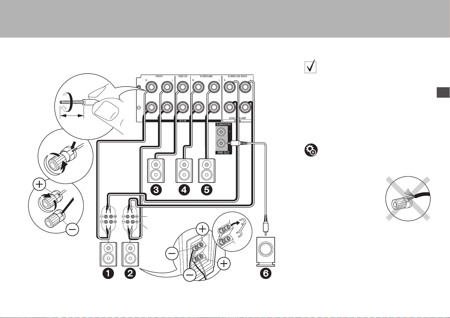
11
> Avant de démarrer > Raccordement > Configuration > Lecture > Nom des pièces
Fr
1
2
1/2˝
(12 mm)
Pour la haute
fréquence
Pour la basse
fréquence
1 Câble d'enceinte, 2 Câble du caisson de basse
dans le cas de :
Page 8
Raccordez des enceintes avant compatibles avec la bi-
amplification aux prises FRONT et aux prises
SURROUND BACK. Assurez-vous de retirer le cavalier
se trouvant entre les prises des graves et les prises des
aigus des enceintes avant. En cas de connexion en bi-
amplification, reportez-vous au mode d'emploi de vos
enceintes. Il est possible de raccorder jusqu'à deux
caissons de basse sous tension. Le même signal est
reproduit par chacune des prises SUBWOOFER.
Vérifiez que les fils dénudés des enceintes ne dépassent pas des
bornes d'enceinte lors du raccordement. Si les fils dénudés des
enceintes entrent en contact avec le panneau arrière ou si les fils
+ et – se touchent, le circuit de protection sera activé.
Configuration
0 La bi-amplification nécessite que vous changiez
certains réglages. Sélectionnez "Yes" dans "Bi-
Amp" de "1. MCACC automatique intégrale"
(
P19) dans la Initial Setup.
SN29402194_VSX-301_BAS_Fr.book 11 ページ 2016年1月6日 水曜日 午前12時10分
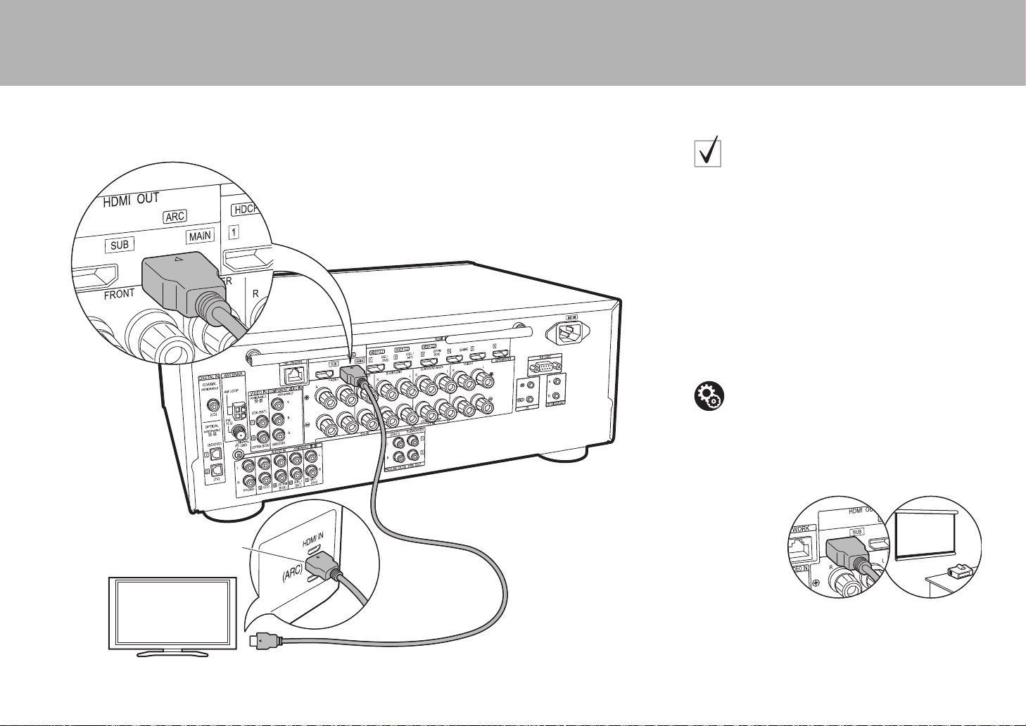
12
> Avant de démarrer > Raccordement > Configuration > Lecture > Nom des pièces
Étape 3 : Raccordez le téléviseur
HDMI IN (ARC)
1
TV
1 Câble HDMI
si vous avez :
ARC TV
Cet appareil se branche entre votre téléviseur et les
appareils AV. Si vous raccordez deux appareils AV ou
plus, vous pouvez choisir la vidéo à afficher sur le
téléviseur et le son reproduit par cet appareil en
changeant le sélecteur d'entrée.
Voici les raccordements pour un téléviseur qui prend en
charge la fonctionnalité ARC (Audio Return Channel). En
raccordant un seul câble HDMI, vous pouvez non
seulement reproduire la vidéo entrant dans cet appareil
vers le téléviseur, mais vous pouvez également lire le son
du téléviseur via cet appareil.
Pour le raccordement, choisissez une prise HDMI IN du
téléviseur qui prend en charge la fonctionnalité ARC.
Un autre téléviseur ou projecteur peut être raccordé à la prise
HDMI OUT SUB. Cette prise ne prend pas en charge la
fonctionnalité ARC. Pour avoir des détails sur la manière de
reproduire la vidéo vers un dispositif raccordé (P21)
Configuration
0 Des réglages sont nécessaires pour utiliser la
fonctionnalité ARC. Sélectionnez "Yes" dans "5.
Audio Return Channel" (
P20) dans la Initial
Setup.
0 Veuillez lire le mode d'emploi du téléviseur pour
connaitre le sens des raccordements et la
configuration du téléviseur.
SN29402194_VSX-301_BAS_Fr.book 12 ページ 2016年1月6日 水曜日 午前12時10分
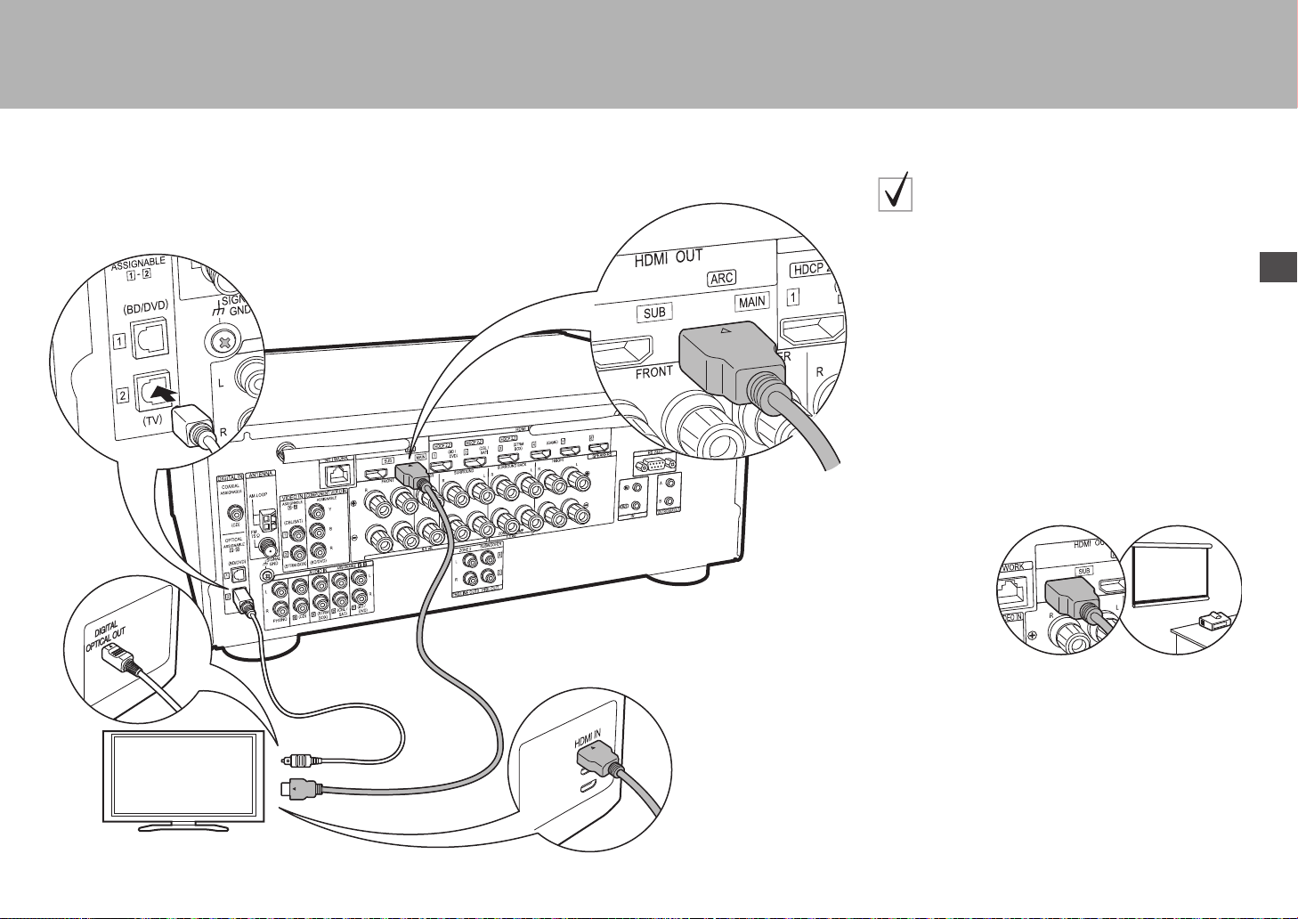
13
> Avant de démarrer > Raccordement > Configuration > Lecture > Nom des pièces
Fr
TV
12
1 Câble HDMI, 2 Câble optonumérique
si vous avez :
Non-ARC TV
Cet appareil se branche entre votre téléviseur et les
appareils AV. Si vous raccordez deux appareils AV ou
plus, vous pouvez choisir la vidéo à afficher sur le
téléviseur et le son reproduit par cet appareil en
changeant le sélecteur d'entrée.
Ceci décrit les raccordements pour un téléviseur qui ne
prend pas en charge la fonctionnalité ARC (Audio Return
Channel). En raccordant un câble HDMI ainsi qu'un câble
optonumérique, vous pouvez non seulement reproduire la
vidéo entrant dans cet appareil vers le téléviseur, mais
vous pouvez également lire le son du téléviseur via cet
appareil.
0 Le raccordement d'un câble optonumérique n'est pas
nécessaire si vous regardez la télévision via un
décodeur (qui n'utilise pas le tuner du téléviseur).
Un autre téléviseur ou projecteur peut être raccordé à la prise
HDMI OUT SUB. Cette prise ne prend pas en charge la
fonctionnalité ARC. Pour avoir des détails sur la manière de
reproduire la vidéo vers un dispositif raccordé (P21)
SN29402194_VSX-301_BAS_Fr.book 13 ページ 2016年1月6日 水曜日 午前12時10分
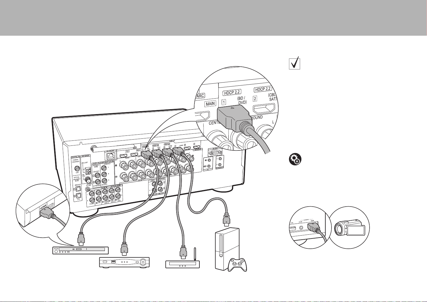
14
> Avant de démarrer > Raccordement > Configuration > Lecture > Nom des pièces
Étape 4 : Raccordez les appareils AV
BD/DVD
GAME
1
Décodeur câble/
satellite
Lecteur de contenu
multimédia en flux
1 Câble HDMI
si vous avez :
Des appareils AV HDMI
Il s'agit d'un exemple de raccordement avec un appareil
AV possédant une prise HDMI. Avec le raccordement d'un
appareil AV conforme à la norme CEC (Consumer
Electronics Control), vous pouvez utiliser des
fonctionnalités comme le HDMI CEC qui est lié au
sélecteur d'entrée, et le HDMI Standby Through qui vous
permet de lire la vidéo et le son provenant d'un appareil
AV sur le téléviseur même si cet appareil est en veille.
0 Pour lire une vidéo en 4K ou en 1080p, utilisez un
câble HDMI haute vitesse. De plus, pour profiter d'une
vidéo compatible HDCP2.2, raccordez les prises HDMI
IN1 à IN3.
Vous pouvez raccorder un appareil comme un caméscope à la
prise AUX INPUT HDMI de la façade avant.
Configuration
0 La configuration HDMI (
P20) est nécessaire
pour utiliser les fonctionnalités HDMI CEC et HDMI
Standby Through. Faites les réglages une fois que
tous les raccordements ont été effectués.
0 Pour bénéficier du son surround numérique, y
compris Dolby Digital, la sortie audio devra être
réglée sur "Bitstream output" sur le lecteur Blu-ray
ou les autres appareils raccordés.
SN29402194_VSX-301_BAS_Fr.book 14 ページ 2016年1月6日 水曜日 午前12時10分
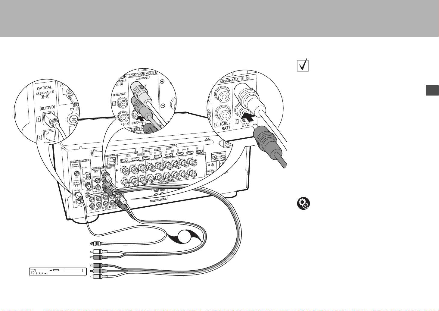
15
> Avant de démarrer > Raccordement > Configuration > Lecture > Nom des pièces
Fr
OR
BD/DVD
1
2
3
1 Câble vidéo composante, 2 Câbleoptonumérique, 3 Câble audio analogique
si vous avez :
Des appareils AV non
HDMI
Il s'agit d'un exemple de raccordement avec un appareil
AV ne possédant pas de prise HDMI. Effectuez les
raccordements de l'appareil AV en fonction des prises
qu'il possède. Si le raccordement pour l'entrée vidéo est
effectué à la prise BD/DVD, le raccordement pour l'entrée
audio devra également se faire aux prises BD/DVD, et
ainsi de suite, de manière à raccorder les entrées vidéo et
les entrées audio portant le même nom. Notez que les
signaux vidéo entrant par la prise VIDEO IN ou les prises
COMPONENT VIDEO IN seront convertis de façon
ascendante en signaux HDMI puis reproduit par la prise
HDMI OUT.
0 Pour profiter de la lecture surround numérique dans
des formats comme le Dolby Digital, vous devez
effectuer un raccordement avec un câble coaxial
numérique ou un câble optonumérique pour les
signaux audio.
Configuration
0 Les prises COMPONENT VIDEO IN ne sont
compatibles qu'avec les résolutions 480i ou 576i.
Lorsque les signaux vidéo entrent par les prises
COMPONENT VIDEO IN, réglez la résolution de
sortie du lecteur sur 480i ou 576i. Sélectionnez
entrelacé s'il n'y a pas d'option 480i, etc. Si votre
lecteur ne prend pas en charge la sortie 480i ou
576i, utilisez la prise VIDEO IN.
0 Pour bénéficier du son surround numérique, y
compris Dolby Digital, la sortie audio devra être
réglée sur "Bitstream output" sur le Lecteur Blu-ray
ou les autres appareils raccordés.
SN29402194_VSX-301_BAS_Fr.book 15 ページ 2016年1月6日 水曜日 午前12時10分
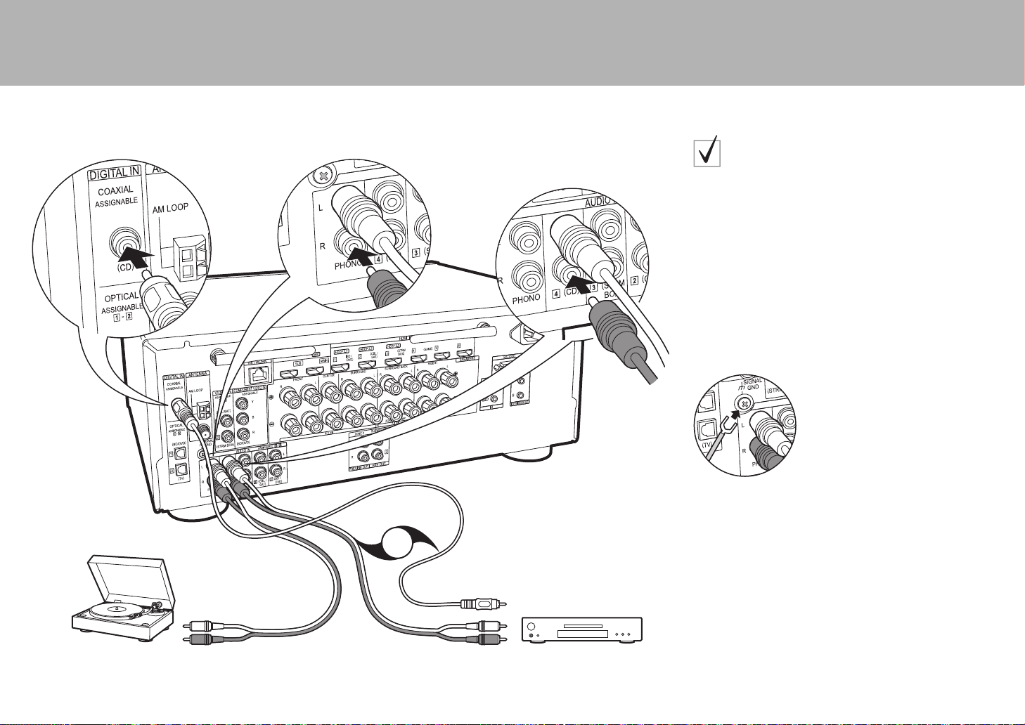
16
> Avant de démarrer > Raccordement > Configuration > Lecture > Nom des pièces
OR
CD
2
1
Platine
disque
1 Câble coaxial numérique, 2 Câble audio analogique
si vous avez :
Des appareils audio
Exemple de raccordement avec un appareil audio.
Raccordez un lecteur CD à l'aide d'un câble coaxial
numérique ou d'un câble audio analogique. Vous pouvez
également raccorder une platine disque possédant une
cartouche de type MM à la prise PHONO.
0 Si la platine disque possède un égaliseur audio intégré,
branchez-la à une autre prise AUDIO IN. De plus, si la
platine disque utilise une cartouche de type MC,
installez un égaliseur audio compatible avec les
cartouches de type MC entre l'appareil et la platine
disque, puis raccordez n'importe quelle prise AUDIO IN
autre que la prise PHONO.
Si la platine disque a un fil de mise à la terre, branchez-le à la
borne SIGNAL GND de cet appareil.
SN29402194_VSX-301_BAS_Fr.book 16 ページ 2016年1月6日 水曜日 午前12時10分
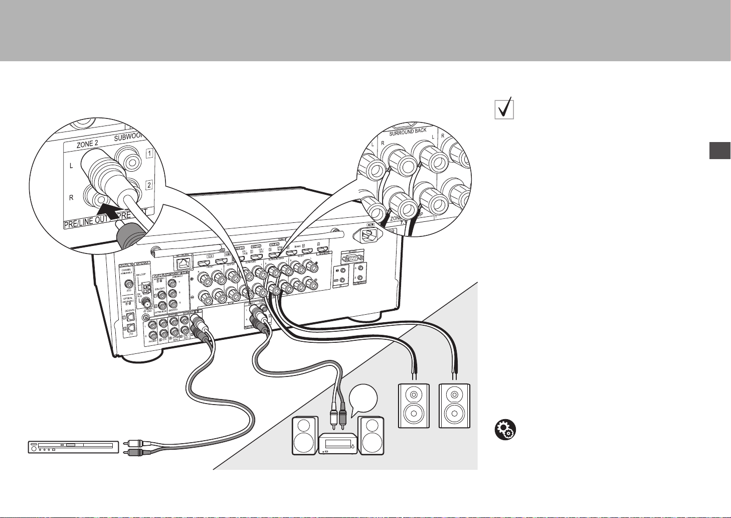
17
> Avant de démarrer > Raccordement > Configuration > Lecture > Nom des pièces
Fr
BD/DVD
ZONE2 PRE/LINE OUT
ZONE SPEAKER
1
2
ZONE2
LINE
IN
MAIN ROOM
1 Câble audio analogique, 2 Câble d'enceinte
Raccordement multizone
Vous pouvez écouter le son dans une pièce différente, par
exemple, en faisant jouer un lecteur de Blu-ray Disc dans
la pièce principale (là où cet appareil est situé) et en
écoutant la radio Internet dans une autre pièce (ZONE 2).
0 Les signaux audio DSD et Dolby TrueHD ne sont pas
reproduits vers la ZONE 2 si sélectionnés avec le
sélecteur d'entrée "NET".
Raccordements avec un appareil AV
Pour reproduire le son d'un appareil AV externe vers la
ZONE 2, vous devez effectuer le raccordement à l'aide
d'un câble audio analogique.
ZONE 2 PRE/LINE OUT
Il est possible de lire une source à 2 voies dans une autre
pièce pendant qu'une source 7.1 est lue dans la pièce
principale. Branchez les prises ZONE 2 PRE/LINE OUT
de l'appareil et les prises LINE IN de l'amplificateur
principal ou l’amplificateur sous tension situé dans une
pièce différente à l'aide d'un câble audio analogique.
ZONE SPEAKER
Il est possible de raccorder les enceintes situées dans
une autre pièce et de lire des sources à 2 voies.
0 Vous pouvez lire avec un système 5.1 maximum dans
la pièce principale durant la lecture dans la ZONE 2.
Les modes d'écoute comme les modes Dolby Atmos
ne peuvent pas être sélectionnés.
0 Notez que le son n’est pas réliqué par enceinte B
lorsque Zone Speaker est utilisé.
Configuration
0 Des réglages sont nécessaires dans la Initial
Setup, "4. Configuration Multi Zone" (
P20) pour
bénéficier de cette fonctionnalité.
SN29402194_VSX-301_BAS_Fr.book 17 ページ 2016年1月6日 水曜日 午前12時10分

18
> Avant de démarrer > Raccordement > Configuration > Lecture > Nom des pièces
Étape 5 : Raccordement d'autres câbles
Raccordement de l'antenne
Déplacez l'antenne tout en écoutant la radio pour trouver
la meilleure position de réception. Utilisez une punaise ou
quelque chose de similaire pour accrocher le fil de
l'antenne FM intérieure au mur.
Antenne cadre AM
Antenne FM intérieure
AM
FM
Raccordement au réseau
Connectez cet appareil au réseau à l'aide du LAN filaire ou
du Wi-Fi (LAN sans fil). Vous pouvez profiter des
fonctionnalités réseau comme la radio Internet, Music
Server et AirPlay en connectant l'appareil au réseau.
Si vous vous connectez par LAN filaire, raccordez un câble
Ethernet au port NETWORK comme montré sur
l'illustration. Pour vous connecter par Wi-Fi, après avoir
sélectionné "Wireless" dans "3. Connexion au réseau"
(
P20) de la Initial Setup, sélectionnez la méthode de
réglage désirée et suivez les instructions à l'écran pour
configurer la connexion.
Branchement du cordon d'alimentation
Branchez le cordon d'alimentation à la prise électrique
après avoir effectué tous les autres raccordements.
Branchez le cordon d'alimentation à la prise AC IN de
l'appareil et à la prise électrique. Débranchez toujours la
prise électrique en premier lorsque vous retirez le cordon
d'alimentation.
SN29402194_VSX-301_BAS_Fr.book 18 ページ 2016年1月6日 水曜日 午前12時10分
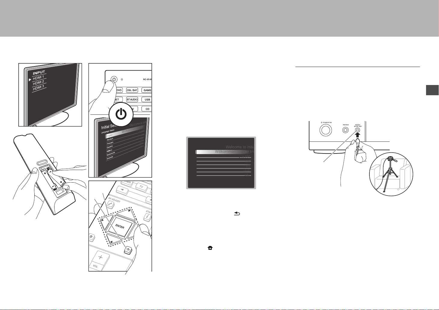
19
> Avant de démarrer > Raccordement > Configuration > Lecture > Nom des pièces
Fr
Étape 6 : Mise sous tension & Configuration initiale
Pour refaire la configuration initiale
Une fois tous les raccordements effectués, changez
l'entrée du téléviseur pour l'entrée de cet appareil,
introduisez les piles dans la télécommande et appuyez sur
Í pour mettre sous tension. Lorsque vous mettez en
marche l'appareil pour la première fois, la Initial Setup
s'affiche automatiquement sur le téléviseur pour vous
permettre d'effectuer les réglages nécessaires au
démarrage en utilisant des commandes simples en suivant
le guide à l'écran.
Ces instructions vous guideront à travers certains
éléments que vous devez vérifier à l'avance. Lisez-les au
préalable pour que la configuration s'effectue sans soucis.
Fonctionnement
Sélectionnez l'élément à l'aide des touches du curseur de
la télécommande et appuyez sur ENTER (a). Pour revenir
sur l'écran précédent, appuyez sur (b).
Pour refaire la Initial Setup
Si vous interrompez la procédure en cours ou si vous
désirez modifier un réglage effectué lors de la Initial Setup,
appuyez sur la touche de la télécommande,
sélectionnez "System Setup" – "Miscellaneous" – "Initial
Setup" depuis Home, et appuyez sur ENTER.
1. MCACC automatique intégrale
Positionnez le microphone de configuration d'enceinte
fourni sur la position d'écoute, mesurez les tonalités de
test émises par les enceintes, l'appareil règle alors
automatiquement le niveau de volume optimal pour
chaque enceinte, les fréquences de croisement, et la
distance depuis la position d'écoute. Ceci active
également la correction de la déformation causée par
l'environnement acoustique de la pièce.
0 Utilisez un trépied ou quelque chose de similaire pour
placer le microphone de configuration d'enceinte à
hauteur d'oreille.
0 Le son du caisson de basse peut ne pas être détecté
car il est de fréquence extrêmement basse. Réglez le
volume du caisson de basse à plus de la moitié.
0 Le calibrage peut durer plusieurs minutes. Les
enceintes émettent la tonalité de test à haut volume
durant les mesures, soyez donc prudent avec votre
entourage. Gardez la pièce aussi silencieuse que
possible lors des mesures. Si les mesures sont
interrompues, éteignez les appareils électroménagers.
a
b
Initial Setup
Language Select
English
Deutsch
Français
Español
Italiano
Nederlands
Svenska
MCACC
SETUP MIC
SN29402194_VSX-301_BAS_Fr.book 19 ページ 2016年1月6日 水曜日 午前12時10分
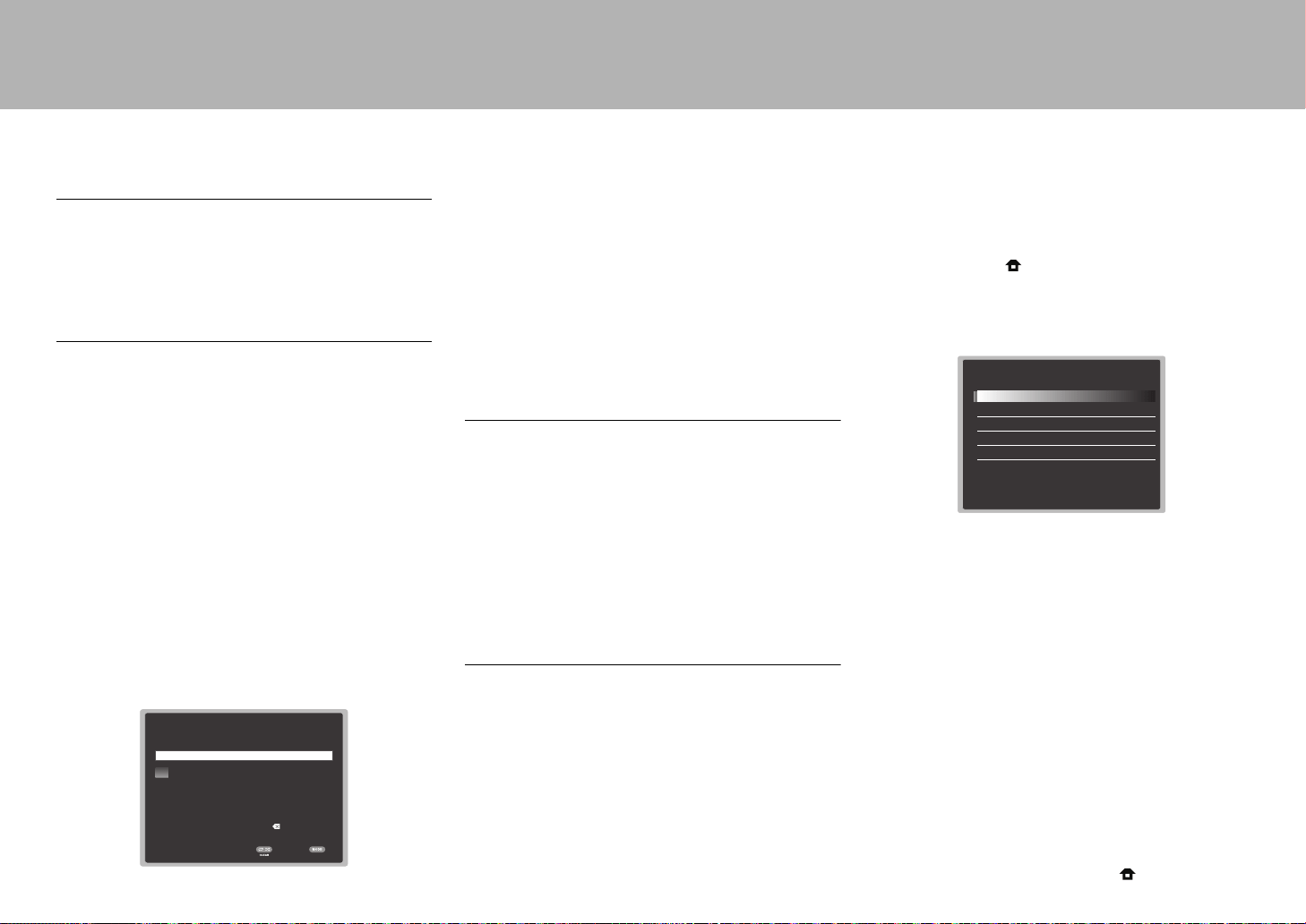
20
> Avant de démarrer > Raccordement > Configuration > Lecture > Nom des pièces
2. Connexion de la source
Vérifiez que chaque source d'entrée est correctement raccordée.
Suivez le guide, sélectionnez l'entrée que vous désirez vérifier,
démarrez la lecture sur le lecteur sélectionné, et vérifiez que les
images apparaissent sur le téléviseur et que le son est lu.
3. Connexion au réseau
Configurez la connexion Wi-Fi avec un point d'accès tel
qu'un routeur LAN sans fil. Il existe les deux méthodes de
connexion au Wi-Fi suivantes :
"Scan Networks": Recherchez un point d'accès depuis cet
appareil. Récupérez le SSID du point d'accès au préalable.
"Use iOS Device (iOS7 or later)": Partagez les
paramètres Wi-Fi du dispositif iOS avec cet appareil.
Si vous sélectionnez "Scan Networks", il y a deux choix de
méthode de connexion supplémentaires. Vérifiez ce qui suit :
0 "Enter Password": Saisissez le mot de passe (ou clé)
du point d'accès à connecter.
0 "Push Button": Si le point d'accès a une touche de
connexion automatique, vous pouvez vous connecter
sans saisir de mot de passe.
0 Si le SSID du point d'accès ne s'affiche pas, alors dans
la liste des SSID, sélectionnez "Other..." avec les
touches du curseur de la télécommande et appuyez
sur ENTER, puis suivez les instructions à l'écran.
Saisie clavier
Pour permuter entre les majuscules et les minuscules,
sélectionnez "A/a" sur l'écran et appuyez sur ENTER. Pour
choisir de masquer le mot de passe par des " * " ou de
l'afficher textuellement, appuyez sur la touche +Fav de la
télécommande. Appuyez sur CLEAR pour supprimer tous
les caractères saisis.
0 Un écran de confirmation vous demandant d'accepter la
politique de confidentialité s'affiche pendant la
configuration du réseau. Sélectionnez "Yes" et appuyez
sur ENTER pour accepter.
4. Configuration Multi Zone
Lorsque vous désirez bénéficier du son dans une autre
pièce que la pièce principale, réglez la méthode de sortie
audio pour la pièce séparée (ZONE 2). Si vous avez
raccordé des enceintes dans une pièce différente à l'aide
d'un câble d'enceinte, sélectionnez "Using AV Receiver". Si
vous avez raccordé un amplificateur principal dans une
pièce différente à l'aide d'un câble audio analogique,
sélectionnez "with External Premain Amplifier". Si vous
avez raccordé un amplificateur de puissance, sélectionnez
"with External Power Amplifier".
5. Audio Return Channel
Si vous avez raccordé un téléviseur qui prend en charge la
fonctionnalité ARC, sélectionné "Yes". Le paramètre ARC
de cet appareil s'active et vous pouvez écouter le son du
téléviseur via cet appareil.
Wi-Fi Setup
SSID
When finished, select the "OK" key.
**
OKA/a
a b cdef gh i jklm
nopqr s tuvwxy z
1 2 3456789 0-^ \
,./;:@[]
A/aAll Erase
Configuration HDMI
HDMI CEC
Effectuez ce réglage pour activer la fonctionnalité de
contrôle des dispositifs conformes avec la norme CEC.
Ceci est automatiquement activé si vous avez sélectionné
"Yes" dans "5. Audio Return Channel" de la Initial Setup.
Appuyez sur la touche de la télécommande pour régler
"System Setup" – "Hardware" – "HDMI" – "HDMI CEC" sur "On"
sur l'écran du téléviseur. Active également la fonctionnalité de
contrôle CEC sur le dispositif CEC que vous avez raccordé.
HDMI Standby Through
Même si cet appareil est en veille, les signaux entrant
depuis les appareils AV sont transmis au téléviseur.
0 "Auto" / "Auto (Eco)": Sélectionnez l'un de ces
paramètres si vous avez raccordé des appareils AV
conformes à la norme CEC. Indépendamment du
sélecteur d'entrée sélectionné immédiatement avant le
passage de l'appareil en veille, vous pouvez transmettre
les signaux entrant depuis les appareils AV au téléviseur.
Sélectionnez "Auto (Eco)" si le téléviseur est également
conforme CEC. Vous pouvez réduire la consommation
d'énergie en mode veille.
0 "Noms du sélecteur d'entrée pour BD/DVD, etc." :
Vous pouvez transmettre les signaux entrant depuis le
sélecteur d'entrée sélectionné au TV. Il peut être
sélectionné lorsque "HDMI CEC" est paramétré sur "Off".
0
"Last":
Vous pouvez transférer les signaux entrant du
sélecteur d'entrée immédiatement sélectionné avant la mise
en veille de l'appareil.
Il peut être sélectionné lorsque
"HDMI CEC" est paramétré sur "Off".
Pour quitter les réglages, appuyez sur .
HDMI
HDMI CEC
HDMI Standby Through
Audio TV Out
Audio Return Channel
Auto Delay
On
Auto(Eco)
Auto
Auto
On
SN29402194_VSX-301_BAS_Fr.book 20 ページ 2016年1月6日 水曜日 午前12時10分
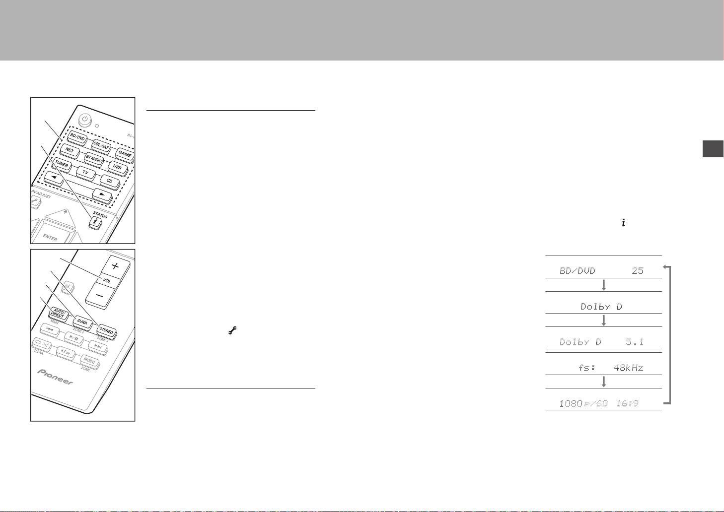
21
> Avant de démarrer > Raccordement > Configuration >Lecture > Nom des pièces
Fr
Lecture de base
Lecture d'un appareil AV
1. Réglez l'entrée du téléviseur sur celle
assignée à l'appareil.
2. Appuyez sur le sélecteur d'entrée (a) de la
télécommande portant le même nom que la
prise à laquelle vous avez raccordé le lecteur
pour changer l'entrée.
Par exemple, appuyez sur la touche BD/DVD
pour lire le lecteur raccordé à la prise BD/
DVD. Appuyez sur TV pour écouter le son du
téléviseur.
Vous pouvez également sélectionner l’entrée
à l'aide des touches 21.
0 Lorsque la fonction de liaison CEC
marche, l'entrée change automatiquement
si vous avez raccordé un téléviseur et un
lecteur conformes CEC à cet appareil à
l'aide d'un raccordement HDMI.
3. Démarrez la lecture sur le lecteur.
4. Utilisez VOL+/– (b) pour régler le volume.
Lorsqu'un téléviseur est raccordé à la prise
HDMI OUT SUB
Appuyez sur la touche de la télécommande
pour afficher le AV Adjust et réglez "Other" –
"HDMI Out" sur "SUB" ou "MAIN+SUB".
Mode d'écoute
Cet appareil est équipé de plusieurs modes
d'écoute. Pour plus de détails sur les modes
d'écoute, voir le Manuel Avancé. Cette section
présente les modes les plus populaires.
0 Une future mise à jour du micrologiciel est
prévue pour permettre à cet appareil de
prendre en charge la lecture du format audio
DTS Neural:X. Neo:6 Cinema et Neo:6 Music
sont disponibles jusqu’à une mise à jour.
Touche AUTO/DIRECT (c)
Vous pouvez sélectionner les modes Auto
Surround, Direct et Pure Direct. Dans chaque
cas, pour les signaux entrant sur 2 canaux le
mode Stereo est automatiquement sélectionné
et reproduit seulement avec les enceintes avant
et le subwoofer, tandis que pour le signal
d'entrée multicanal sont automatiquement
sélectionnés des modes qui correspondent au
signal entrant, c'est à dire Dolby Digital pour les
sources Dolby Digital, et DTS-HD Master Audio
pour DTS-HD Master Audio. Le mode Direct
coupe certaines fonctions qui peuvent affecter la
qualité du son, comme les commandes de
tonalité, ce qui vous fera profiter d'une qualité
sonore encore meilleure. Le mode Pure Direct
coupe plusieurs fonctions qui peuvent affecter la
qualité du son, vous aurez ainsi une
reproduction plus fidèle du son original. Dans ce
cas, le réglage d'enceinte par MCACC est
désactivé.
0 En fonction du signal entrant et de la
configuration de l'enceinte, peuvent être
automatiquement sélectionnés les modes
Dolby Surround et DTS Neural:X qui étendent
les signaux d'entrée 2 canaux et 5.1 aux
formats 5.1 et 7.1.
Touche SURR (d)
Vous pouvez sélectionner plusieurs modes
d'écoute selon votre goût. Il y a les modes Dolby
Digital, DTS-HD Master Audio, et Stereo que
vous pouvez choisir selon le signal en entrée,
ou les modes Dolby Surround et DTS Neural:X
qui étendent les signaux d'entrée 2 canaux et
5.1 aux formats 5.1 ou 7.1. Vous pouvez
également bénéficier des modes surround
originaux comme les modes Ext.Stereo et
Drama.
Touche STEREO (e)
Vous pouvez sélectionner le mode "Stereo" pour
lire uniquement depuis les enceintes avant et le
caisson de basse.
Le mode d'écoute que vous avez sélectionné en
dernier pour la source est gardé en mémoire
pour chacune des touches AUTO/DIRECT,
SURR et STEREO. Si le contenu que vous lisez
n'est pas pris en charge par le mode d'écoute
que vous avez sélectionné en dernier, le mode
d'écoute normal pour le contenu en question est
automatiquement sélectionné.
Appuyez plusieurs fois sur (f) pour changer
l'afficheur de l'appareil principal dans cet ordre :
f
a
b
c
d
e
SN29402194_VSX-301_BAS_Fr.book 21 ページ 2016年1月6日 水曜日 午前12時10分
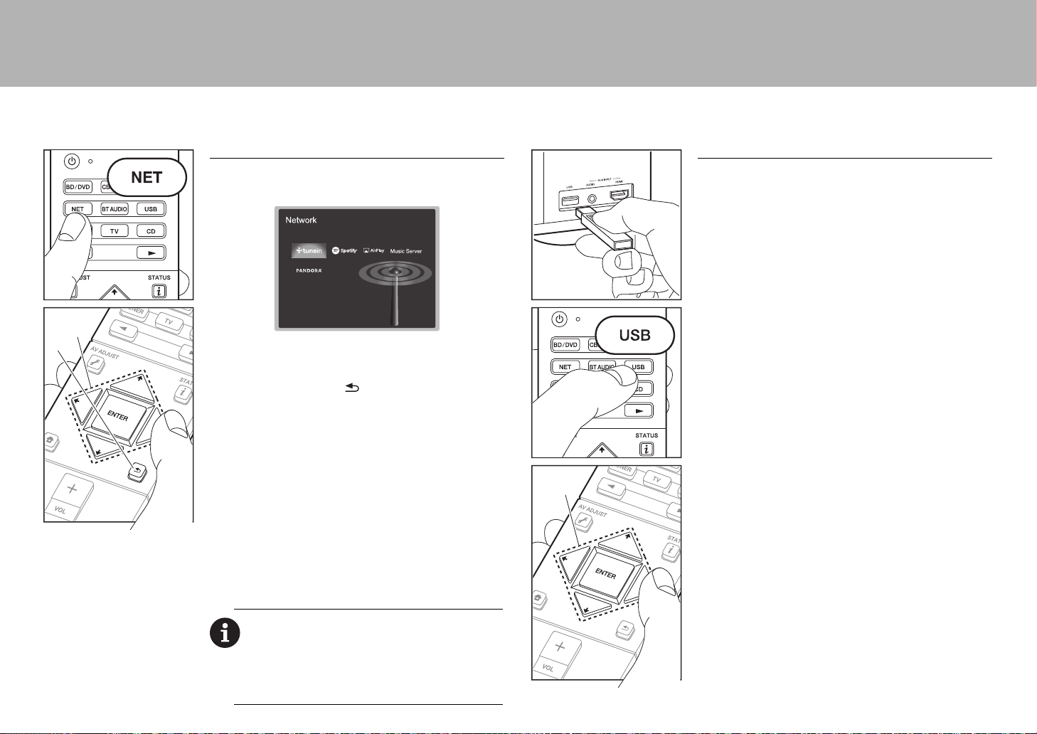
22
> Avant de démarrer > Raccordement > Configuration >Lecture > Nom des pièces
Fonctions réseau
Services réseau
1. Réglez l'entrée du téléviseur sur celle assignée à l'appareil.
2. Appuyez sur NET pour afficher l'écran de la liste des services réseau.
3. Sélectionnez l'élément à l'aide des touches du curseur
de la télécommande et appuyez sur ENTER pour
valider votre sélection (a). Pour revenir sur l'écran
précédent, appuyez sur (b).
Radio Internet
Lorsque cet appareil est connecté au réseau, vous pouvez écouter
TuneIn ou d'autres services de radio Internet préenregistrés. Après avoir
sélectionné le service désiré, suivez les instructions à l'écran, en utilisant
les touches du curseur pour sélectionner les stations de radio et les
programmes, puis appuyez sur ENTER pour écouter. La lecture démarre
lorsque le tampon affiche 100%.
Music Server
Vous pouvez lire les fichiers de musique présents sur les ordinateurs ou
dispositifs NAS du réseau domestique connectés au même réseau que
cet appareil. Sélectionnez le serveur avec les touches du curseur,
sélectionnez le fichier musical désiré et appuyez sur ENTER pour lancer
la lecture. La lecture démarre lorsque le tampon affiche 100%.
Remarques :
0
Les services réseau peuvent être sélectionnés une fois que le réseau
démarre même s'ils ne pouvaient pas être sélectionnés au préalable.
0
La fonctionnalité peut être introduite par des mises à jour du
micrologiciel et les services des fournisseurs de service pourraient cesser
et le contenu devenir indisponible à l’avenir. De plus, les services
disponibles peuvent varier en fonction de votre lieu de résidence.
a
b
USB
Lisez des fichiers musicaux sur un périphérique de
stockage USB.
0 Cette commande n'est pas garantie pour tous les
périphériques de stockage USB.
1. Branchez votre périphérique de stockage USB
contenant les fichiers de musique au port USB situé à
l'avant de l'appareil.
2. Appuyez sur USB sur la télécommande.
3. Sélectionnez le dossier de votre choix ou un fichier
musical avec les curseurs de la télécommande et
appuyez sur ENTER pour confirmer et commencer la
lecture (a).
0 Cet appareil peut utiliser les périphériques de stockage
USB conformes à la norme USB MSC. L'appareil est
également compatible avec les périphériques de
stockage USB utilisant les formats de système de fichier
FAT16 ou FAT32.
a
SN29402194_VSX-301_BAS_Fr.book 22 ページ 2016年1月6日 水曜日 午前12時10分
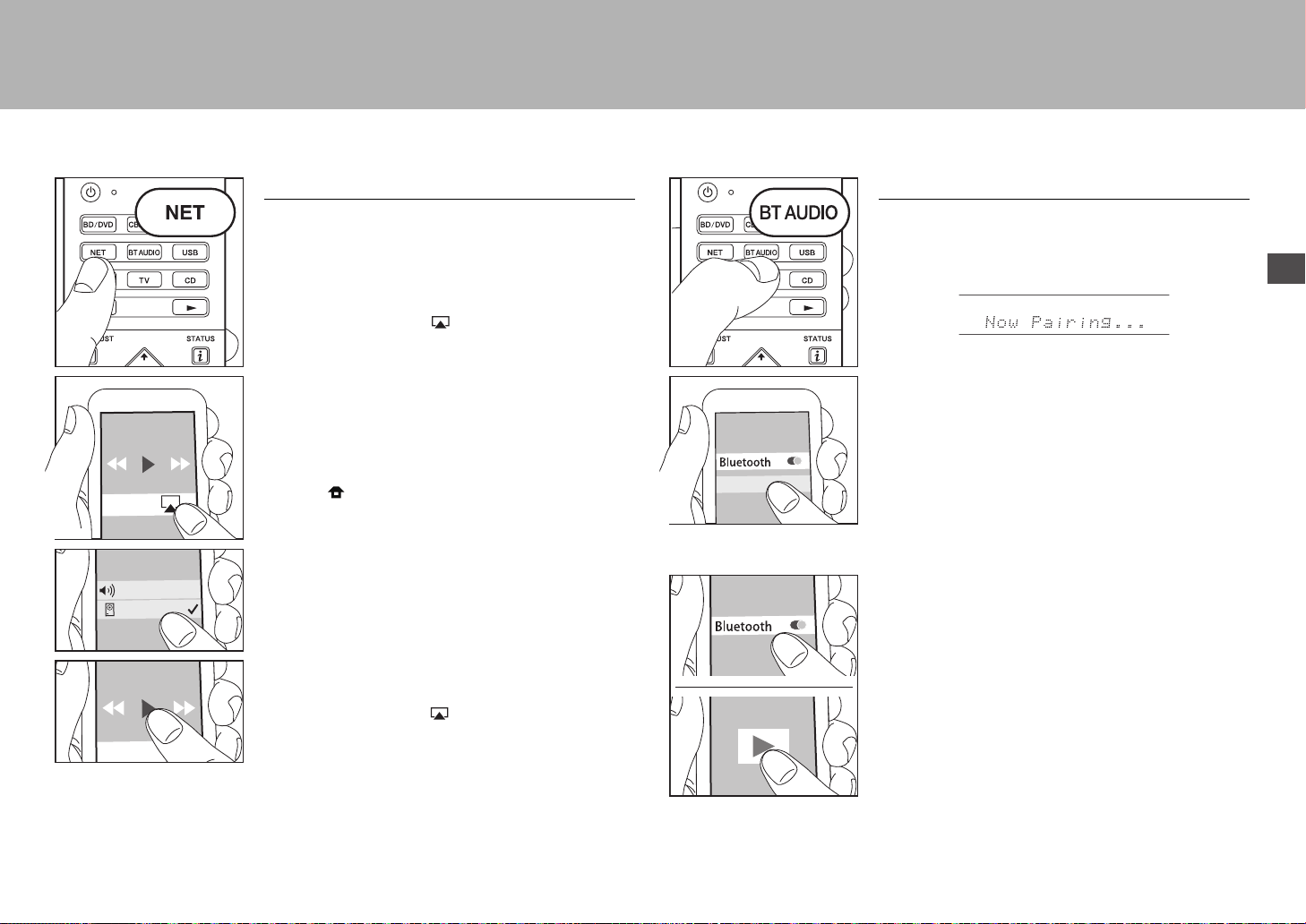
23
> Avant de démarrer > Raccordement > Configuration >Lecture > Nom des pièces
Fr
AirPlay
Vous pouvez profiter à distance des fichiers musicaux
présents sur un iPhone
®
, iPod touch
®
, ou un iPad
®
connecté au même point d'accès que cet appareil.
0 Mettez à jour la version OS de votre périphérique iOS.
1. Connectez le dispositif iOS au point d'accès.
2. Appuyez sur NET.
3. Touchez l'icône AirPlay présente dans le centre de
contrôle du dispositif iOS et sélectionnez cet appareil
dans la liste des dispositifs affichée, puis touchez
"Done".
4. Lisez les fichiers musicaux sur le dispositif iOS.
0 La fonctionnalité Network Standby est active par défaut,
donc lorsque vous effectuez les étapes 3 et 4 ci-dessus,
cet appareil se met automatiquement en marche et
l'entrée passe sur "NET". Pour réduire la quantité
d'énergie consommée en mode veille, appuyez sur la
touche de la télécommande, puis dans le Home
affiché, réglez "System Setup" – "Hardware" – "Power
Management" – "Network Standby" sur "Off".
0 À cause des caractéristiques de la technologie sans fil
AirPlay, le son produit par cet appareil peut être
légèrement en retard par rapport au son lu par le
périphérique compatible AirPlay.
Vous pouvez également lire des fichiers musicaux sur
l'ordinateur avec iTunes (Ver. 10.2 ou ultérieure). Avant
d'effectuer cette action, vérifiez que cet appareil et
l'ordinateur sont connectés au même réseau, puis
appuyez sur la touche NET de cet appareil. Ensuite,
cliquez sur l'icône AirPlay dans iTunes, sélectionnez
cet appareil dans la liste des dispositifs affichée et
démarrez la lecture d'un fichier musical.
VSX-XXXXX
iPhone
Lecture BLUETOOTH
®
Jumelage
1. Lorsque vous appuyez sur BT AUDIO de la
télécommande, "Now Pairing..." apparait sur l'afficheur
de l'appareil et le mode appairage s'active.
2. Activez (mettez en marche) la fonction BLUETOOTH du
dispositif compatible BLUETOOTH, puis sélectionnez
cet appareil parmi les dispositifs affichés.
Si un mot de passe est requis, saisissez "0000".
0 Pour connecter un autre dispositif compatible
BLUETOOTH, appuyez sur BT AUDIO jusqu'à ce que
"Now Pairing..." s'affiche, puis effectuez l'étape 2 ci-
dessus. Cet appareil peut mémoriser les données de 8
périphériques appairés.
0 La zone de couverture est de 48 pieds (15 mètres).
Notez que la connexion n'est pas toujours garantie avec
tous les périphériques compatibles BLUETOOTH.
Écouter
1. Lorsque cet appareil est en marche, connectez le
périphérique compatible BLUETOOTH.
2. Le sélecteur d'entrée de cet appareil passera
automatiquement sur "BLUETOOTH".
3. Lisez la musique. Augmentez le volume du périphérique
compatible BLUETOOTH jusqu'à un niveau correct.
0 À cause des caractéristiques de la technologie sans fil
BLUETOOTH, le son produit par cet appareil peut être
légèrement en retard par rapport au son lu par le
périphérique compatible BLUETOOTH.
VSX-XXXXX
SN29402194_VSX-301_BAS_Fr.book 23 ページ 2016年1月6日 水曜日 午前12時10分
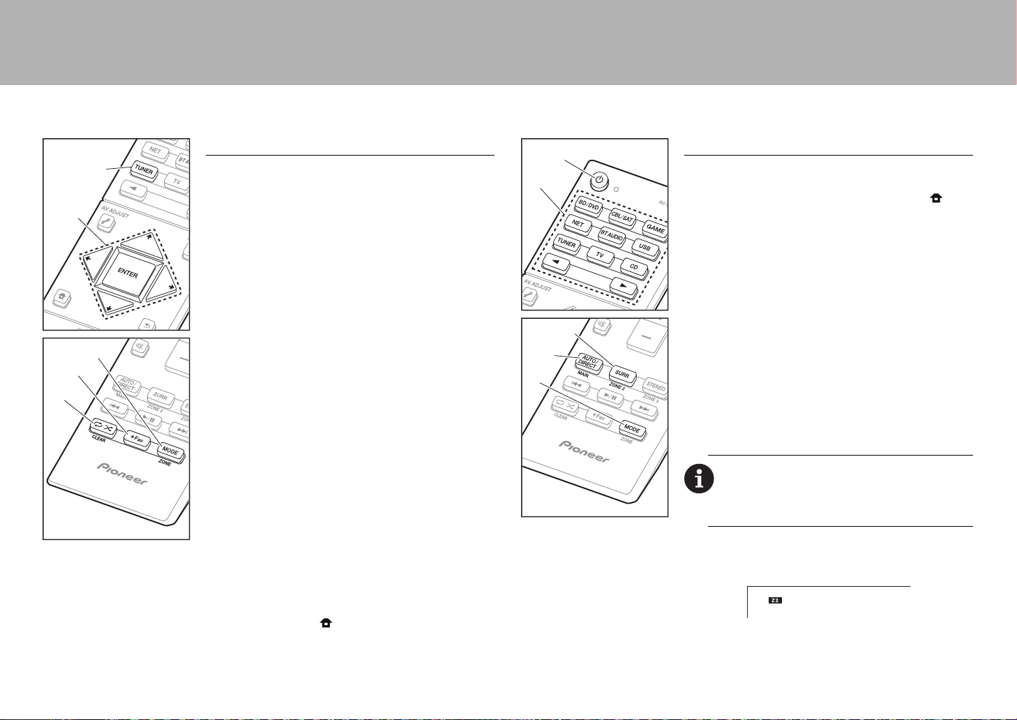
24
> Avant de démarrer > Raccordement > Configuration >Lecture > Nom des pièces
a
Autres
Écoute de la radio
1. Appuyez plusieurs fois sur la touche TUNER (a) de la
télécommande pour sélectionner “AM” ou “FM” sur l'afficheur.
2. Appuyez sur la touche MODE (c) de la télécommande
pour que "TunMode: Auto" soit visualisé sur l'afficheur.
3. Lorsque vous appuyez sur les touches
/
du curseur (b)
de la télécommande, la syntonisation automatique démarre
et la recherche s'arrête lorsqu'une station est trouvée.
Lorsqu'une station de radio est syntonisée, le témoin
“TUNED” s'allume sur l'afficheur.
Vous pouvez prérégler jusqu'à 40 stations.
1. Recherchez la station AM/FM que vous voulez mémoriser.
2. Appuyez sur la touche +Fav (d) de la télécommande
pour que le numéro de préréglage clignote sur
l'afficheur.
3. Pendant que le numéro de préréglage clignote (environ
8 secondes), appuyez plusieurs fois sur les touches
/
du
curseur (b) de la télécommande pour sélectionner un numéro
entre 1 et 40.
4. Appuyez de nouveau sur la touche +Fav (d) de la
télécommande pour mémoriser la station. Lorsqu'il est
enregistré, le numéro de préréglage s'arrête de
clignoter. Pour sélectionner une station de radio
préréglée, appuyez sur les touches / du curseur (b)
de la télécommande.
0 Pour supprimer une station préréglée, appuyez sur les
touches / du curseur (b) de la télécommande pour
sélectionner le numéro de préréglage que vous désirez
supprimer, appuyez sur la touche +Fav (d) de la
télécommande, puis appuyez sur la touche CLEAR (e)
pendant que le numéro de préréglage clignote. Lors de
la suppression, le nombre sur l'écran s'éteint.
Réglage du pas de fréquence
Appuyez sur la touche de la télécommande pour
sélectionner "System Setup" – "Miscellaneous" – "Tuner" –
"AM/FM Frequency Step" et sélectionnez le pas de
fréquence de votre zone. Notez que lorsque ce paramètre
est modifié, toutes les radios préréglées sont supprimées.
c
d
e
a
b
Multizone
Si vous n'avez pas réglé le Multi Zone (
P20) dans Initial
Setup, changez le réglage selon le mode de sortie audio
de l'autre pièce (ZONE 2). Appuyez sur la touche de la
télécommande et effectuez les réglages dans le System
Setup venant de l'écran d'accueil qui s'affiche. Si vous
avez raccordé des enceintes dans une pièce différente à
l'aide d'un câble d'enceinte, sélectionnez "Zone 2" dans
"System Setup" – "Speaker" – "Configuration" – "Zone
Speaker". Si vous avez raccordé un amplificateur de
puissance dans une pièce différente à l'aide d'un câble
audio analogique, alors réglez "System Setup" – "Multi
Zone" – "Zone 2" – "Output Level" sur "Variable" pour
pouvoir régler le volume sur l'appareil.
Lecture
1. Tout en appuyant sur la touche MODE (a) de la
télécommande, appuyez sur ZONE 2 (b) pendant 3
secondes ou plus jusqu'à ce que le témoin à distance
clignote deux fois.
0 La télécommande passe sur le mode de contrôle de
la ZONE 2.
2. Pointez la télécommande vers l'appareil principal et
appuyez sur Í (d).
"Z2" s'allume sur l'afficheur de l’appareil principal.
3. Appuyez sur le sélecteur d'entrée (e) de l'entrée à lire
dans l'autre pièce. Sur l'appareil principal, après avoir
appuyé sur ZONE 2-CONTROL, dans les 8 secondes
qui suivent, tournez la molette du sélecteur pour
Pour passer de nouveau la télécommande sur le mode
de contrôle de la pièce principale : Tout en appuyant sur
MODE (a) de la télécommande, appuyez sur MAIN (c)
pendant 3 secondes ou plus jusqu'à ce que le témoin à
distance clignote une fois.
a
b
c
d
e
SN29402194_VSX-301_BAS_Fr.book 24 ページ 2016年1月6日 水曜日 午前12時10分

25
> Avant de démarrer > Raccordement > Configuration >Lecture > Nom des pièces
Fr
sélectionner l'entrée devant être utilisée dans l’autre
pièce.
0 Vous ne pouvez pas sélectionner des entrées
différentes pour la pièce principale et l'autre pièce
avec le sélecteur d'entrée "NET" ou “BLUETOOTH”
ou "USB". Si vous avez "NET" sélectionné dans la
pièce principale et vous sélectionnez "USB" dans
l'autre pièce, la pièce principale passe à "USB". Vous
ne pouvez pas sélectionner de stations différentes
pour la pièce principale et l'autre pièce avec la radio
AM/FM.
4. Pour régler le volume sur l'appareil, utilisez VOL+/– sur
la télécommande. Pour contrôler avec l'appareil
principal, appuyez sur ZONE 2-CONTROL et réglez
avec la commande MASTER VOLUME dans les 8
secondes.
0 Si la ZONE 2 est activée, la consommation d'énergie
durant la veille augmente par rapport à la normale.
Pour désactiver la fonction
Appuyez sur Í durant le mode de contrôle de la ZONE 2
sur la télécommande. Alternativement, appuyez sur la
touche ZONE 2-ON/OFF de l'appareil principal.
Lecture uniquement dans la ZONE 2
Si vous mettez l’appareil en mode veille pendant une
lecture multi-zone, le témoin Z2 est grisé et le mode de
lecture bascule sur lecture dans une pièce séparée
uniquement. Activer la ZONE 2 tandis que cet appareil est
en veille règlera le mode lecture sur le même paramètre.
AV Adjust
En appuyant sur la touche de la télécommande durant
la lecture, vous pouvez régler les paramètres fréquemment
utilisés, comme le basculement des enceintes et la qualité
du son, à l'aide des menus à l'écran. Sélectionnez l'élément
grâce aux curseurs de la télécommande et appuyez sur
ENTER pour confirmer votre sélection. Pour revenir sur
l'écran précédent, appuyez sur .
"Tone": Il est possible d'améliorer ou de modérer les
basses et les aiguës des enceintes avant. Vous pouvez
régler la qualité du son de l’amplificateur de puissance
raccordé lorsque vous activez ZONE 2.
"Other": Vous permet d’effectuer de nombreux réglages.
0 "Sound Delay": Si la vidéo est en retard sur le son, vous
pouvez retarder le son pour compenser l'écart.
0 "Sound Retriever": Améliore la qualité du son
compressé.
0 "Speakers": Vous pouvez basculer la sortie aux
enceintes surround arrière et aux enceintes en hauteur
et basculer la sortie pour les enceintes A/B.
Home
Si vous appuyez sur sur la télécommande, le Menu
Accueil s’affiche et vous pouvez effectuer les réglages dans
les divers menus. Sélectionnez l'élément grâce aux
curseurs de la télécommande et appuyez sur ENTER pour
confirmer votre sélection. Pour retourner à l'écran
précédent, appuyez sur .
"System Setup": Paramètres avancés pour vous fournir
une expérience encore meilleure.
"MCACC": Configurez les enceintes automatiquement ou
apportez les modifications souhaitées à l'égaliseur.
"Network/Bluetooth": Définissez les paramètres de la
connexion Wi-Fi ou les réglages relatifs au BLUETOOTH.
Lorsque l'appareil fonctionne de façon
irrégulière
(Réinitialisation de cet appareil)
Redémarrer l'appareil peut l’aider à mieux fonctionner.
Pour redémarrer l'appareil, mettez-le en mode veille, après
appuyez sur la touche Í STANDBY/ON sur l’appareil
principal pur au moins 5 secondes. (Les paramètres de
l’appareil seront maintenus.) Si, même après le
redémarrage de l’appareil, aucune amélioration n’est
visible, essayez de débrancher et de rebrancher les
cordons d’alimentation de l’appareil et de l’équipement
raccordé. S’il continue à n’y avoir aucune amélioration,
réinitialiser l'appareil à l'état dans lequel il était au moment
de l'achat peut résoudre le problème. Si vous réinitialisez le
statut de l'appareil, vos préférences seront réinitialisées à
leurs valeurs par défaut. Notez-les avant de commencer
l’opération de réinitialisation ci-dessous.
Comment réinitialiser l'appareil
1. Tout en appuyant sur AUTO/DIRECT de l'appareil
principal, appuyez sur la touche Í STANDBY/ON de
l'appareil principal.
2. "Clear" apparaît sur l'afficheur et l'appareil se remet en
veille. Ne débranchez pas le cordon d'alimentation avant
que "Clear" disparaisse de l'afficheur.
Pour réinitialiser la télécommande, tout en appuyant sur la
touche MODE, appuyez sur jusqu'à ce que le
témoin à distance clignote deux fois (environ 3 secondes).
AV Adjust
Tone
Level
MCACC
Other
Bass
Treble
BD/DVD
SN29402194_VSX-301_BAS_Fr.book 25 ページ 2016年1月6日 水曜日 午前12時10分

26
> Avant de démarrer > Raccordement > Configuration > Lecture > Nom des pièces
Panneau frontal
1. Molette INPUT SELECTOR : Change l'entrée à lire.
2. Témoin MCACC : Il s'allume quand vous avez activé le
mode de réglage d'enceinte par MCACC.
3. Témoin FL OFF : Il s'allume quand vous avez appuyé
sur DIMMER plusieurs fois pour éteindre l'écran.
4. Touche DIMMER : Modifie la luminosité de l'affichage.
5. Touche ZONE 2-ON/OFF : Permet de désactiver la
fonction multizone.
6. Touche ZONE 2-CONTROL : Contrôle la fonction multi-
zone.
7. Touche HOME MENU : Affiche le Home.
8. Afficheur (
P28)
9. Touches du curseur (touche TUNE / PRESET) et
touche ENTER : Sélectionnez l'élément à l'aide des
touches du curseur et appuyez sur ENTER pour
confirmer votre sélection. En utilisant le TUNER,
sélectionnez la fréquence avec TUNE, ou
sélectionnez des stations préréglées avec PRESET.
10.
Témoin NETWORK : Lorsque l'alimentation de l'appareil
est activée, il s'allume si "NET" est sélectionné avec le
sélecteur d'entrée et que l'appareil est connecté au
réseau. Si l'appareil est en mode veille, il s'allume quand
les fonctions comme HDMI CEC and veille réseau sont
activées. Mais il ne s'allume pas lorsque ZONE 2 est
active.
11.
Témoin WIRELESS : S'allume lorsque l'appareil est
connecté au réseau sans fil.
12.
Capteur de la télécommande
13.
Touche RETURN : Permet à l'affichage de retourner à
son état précédent.
14.
MASTER VOLUME : Permet de régler le volume.
15.
Touche Í STANDBY/ON : Permet la mise en marche ou
en veille de l'appareil.
16.
Prise PHONES : Un casque stéréo avec une fiche
standard (1/4 pouce ou ø6,3 mm) est branché.
17.
Prise MCACC SETUP MIC : Le micro de réglage
d'enceinte fourni est connecté.
18.
Touche Mode d’écoute : Sélectionnez le mode d’écoute.
19.
Touche SOUND RETRIEVER : Démarre/arrête la
fonction Sound Retriever qui améliore la qualité du son
compressé.
20.
Touche PURE DIRECT : Passe au mode Pure Direct.
21.
Port USB : Un appareil de stockage USB est connecté
afin que les fichiers musicaux qu'il contient puissent être
lus. Vous pouvez également fournir l'alimentation (5V/
1A) aux périphériques USB avec un câble USB.
22.
Prise AUX INPUT AUDIO/HDMI : Un caméscope ou tout
autre appareil du même type est branché.
12 106121314115798
16
15
22
18 2117
43
19 20
SN29402194_VSX-301_BAS_Fr.book 26 ページ 2016年1月6日 水曜日 午前12時10分
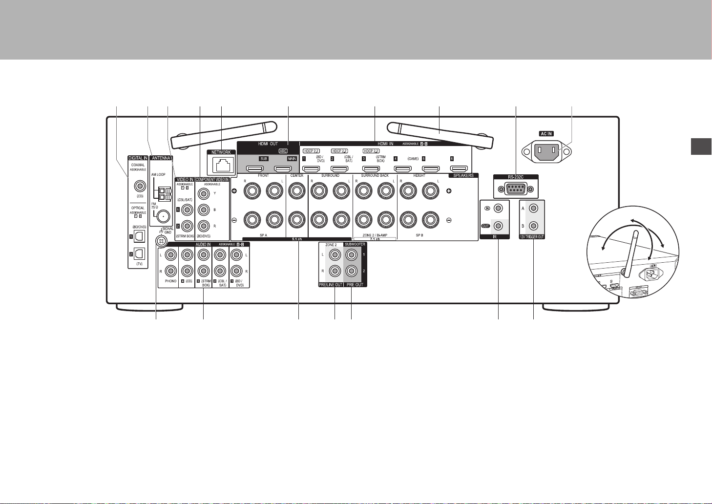
27
Fr
> Avant de démarrer > Raccordement > Configuration > Lecture > Nom des pièces
Panneau arrière
1. Prises DIGITAL IN OPTICAL/COAXIAL : Entrée des
signaux audio numérique composante TV ou AV avec un
câble optonumérique ou un câble coaxial numérique.
2. Borne ANTENNA AM LOOP/FM 75Ω : Les antennes
fournies sont connectées.
3. Prises VIDEO IN : Entrée des signaux vidéo composante
AV avec un câble vidéo analogique.
4. Prises COMPONENT VIDEO IN : Entrée des signaux
vidéo composante AV avec un câble vidéo composante.
5. Port NETWORK : Pour se connecter au réseau à l'aide
d'un câble Ethernet.
6. Prises HDMI OUT : Transmet les signaux vidéo et les
signaux audio avec un câble HDMI raccordé à un écran
comme un téléviseur ou un projecteur.
7. Prises HDMI IN : Transmet les signaux vidéo et les signaux
audio avec un câble HDMI raccordé à un appareil AV.
8. Antenne sans fil : Utilisée pour la connexion Wi-Fi ou
pour utiliser un périphérique compatible BLUETOOTH.
Réglez leurs angles en fonction de l’état de la connexion.
9. Port RS-232C : Pour la connexion au système de
commande de la maison.
10.
AC IN : Le cordon d'alimentation fourni y est branché.
11.
Borne SIGNAL GND : Le fil de terre de la platine disque
est branché.
12.
Prises AUDIO IN : Entrée des signaux audio
composante AV avec un câble audio analogique.
13.
Bornes SPEAKERS : Raccordez les enceintes avec les
câbles d'enceinte.
14.
Prise ZONE 2 PRE/LINE OUT : Sortie des signaux audio
avec un câble audio analogique vers un amplificateur
principal ou un amplificateur sous tension dans une autre
pièce (ZONE 2).
15.
Prise SUBWOOFER PRE OUT : Connectez un caisson
de basse sous tension avec un câble pour caisson de
basse. Il est possible de raccorder jusqu'à deux caissons
de basse sous tension. Le même signal est reproduit par
chacune des prises SUBWOOFER PRE OUT.
16.
Port IR IN/OUT : Vous permet de connecter un kit de
télécommande multi-pièce.
17.
Prises 12V TRIGGER OUT A/B : Vous permet de
connecter un appareil doté d’une prise d'entrée de
déclenchement 12V pour permettre le fonctionnement de
la liaison entre le périphérique et l'appareil.
1211 1413
109
8
8
1
23 5 764
15 16 17
180°
90°
SN29402194_VSX-301_BAS_Fr.book 27 ページ 2016年1月6日 水曜日 午前12時10分
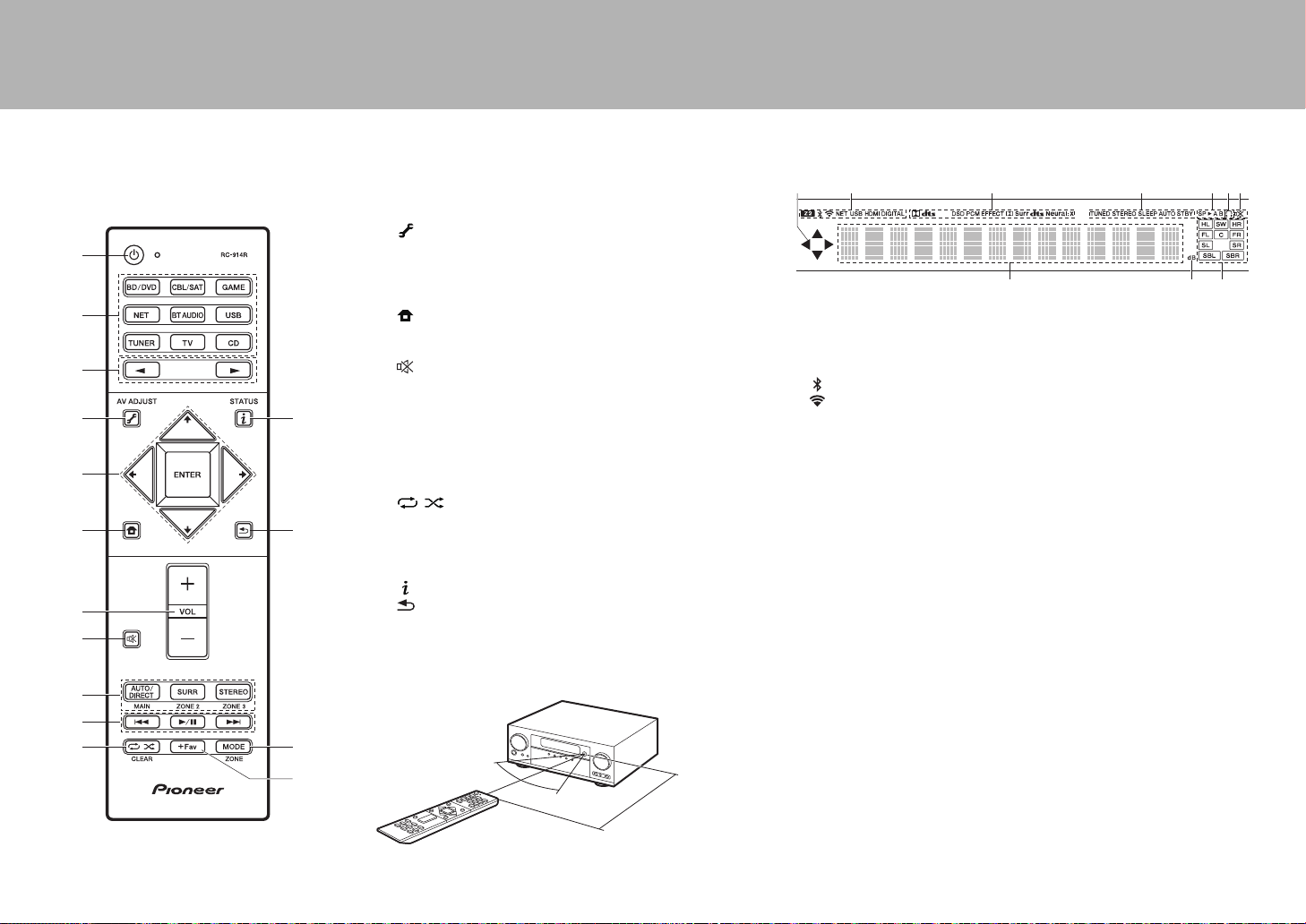
28
> Avant de démarrer > Raccordement > Configuration > Lecture > Nom des pièces
Télécommande
1. Touche Í : Permet la mise en marche ou en veille de l'appareil.
2. Sélecteurs d'entrée : Change l'entrée à lire.
3. Touche 21 : Sélectionnez l'entrée à lire.
4. Touche (AV ADJUST) : Vous pouvez effectuer des réglages
communs sur l'écran du téléviseur.
5. Touches du curseur et touche ENTER : Sélectionnez l'élément à
l'aide des touches du curseur et appuyez sur ENTER pour
confirmer votre sélection.
6. Touche : Affiche le Home.
7. Touche volume : Vous permet d'ajuster le volume. Cette touche
permet également l'annulation de la mise en sourdine.
8. Touche : Mise temporaire de l'audio en sourdine. Appuyez de
nouveau pour annuler la mise en sourdine.
9. Touches LISTENING MODE : Permet de sélectionner le mode
d'écoute.
Touches MAIN/ZONE 2 : Contrôle la fonction multi-zone.
(La touche ZONE 3 ne peut pas être utilisée avec cet appareil.)
10.
Touche Lecture : Utilisé pour les commandes de lecture en lisant
sur Music Server ou par USB.
11.
Touche : Utilisé pour les commandes de répétition de
lecture ou de lecture aléatoire en lisant sur Music Server ou par
USB.
Touche CLEAR : Supprime tous les caractères que vous avez
saisis sur l'écran du téléviseur.
12.
Touche (STATUS) : Modifie l'information affichée.
13.
Touche : Permet à l'affichage de retourner à son état
précédent.
14.
Touche MODE : Permute entre la syntonisation automatique et la
syntonisation manuelle d'une station.
15.
Touche +Fav : Mémorise une station de radio.
9
10
1
2
4
3
6
8
7
5
11
12
14
13
15
30°
30°
Environ 5 m
L'afficheur
1. Ceci peut s'allumer lors des commandes effectuées avec le sélecteur
d'entrée "NET", "USB".
2. S'allume sous les conditions suivantes.
Z2: Lorsque la ZONE 2 est active.
: Lorsque raccordé par BLUETOOTH.
: Lorsque connecté par Wi-Fi.
NET: Lorsque "NET" est sélectionné avec le sélecteur d'entrée et que
l'appareil est connecté au réseau. Il clignotera si la connexion au
réseau n’est pas correcte.
USB: Lorsque "USB" est sélectionné avec le sélecteur d'entrée et que
l'appareil est raccordé par USB et que le périphérique USB est
sélectionné. Clignote si l'USB n’est pas correctement branché.
HDMI : Lors de l'entrée des signaux HDMI et lorsque l'entrée HDMI
est sélectionnée.
DIGITAL : Lors de l'entrée de signaux numériques et lorsque l'entrée
numérique est sélectionnée.
3. S'allume en fonction du type de l'entrée des signaux audio
numériques et du mode d'écoute.
4. S'allume sous les conditions suivantes.
TUNED : Réception de la radio AM/FM.
STEREO : Réception en FM stéréo.
SLEEP : Lorsque la minuterie de veille est définie.
AUTO STBY : La veille automatique est activée.
5. Le système d’enceinte actuellement sélectionné s’allume.
6. S'allume lorsque le casque audio est connecté.
7. S'allume lorsque le volume d'enceinte est en cours de réglage.
8. Affiche différentes informations sur les signaux d'entrée.
9. Il s'allume quand on règle le volume.
10.
Affichage de l'Enceinte/Canal : Affiche le canal de sortie
correspondant au mode d'écoute sélectionné.
14
8
2 3
9
65 7
10
SN29402194_VSX-301_BAS_Fr.book 28 ページ 2016年1月6日 水曜日 午前12時10分
29
Fr
Informations relatives à la licence et à la
marque commerciale
Manufactured under license from Dolby Laboratories. Dolby, Dolby Atmos,
Dolby Surround and the double-D symbol are trademarks of Dolby
Laboratories.
For DTS patents, see http://patents.dts.com. Manufactured under license from
DTS, Inc. DTS, the Symbol, DTS in combination with the Symbol, the DTS-HD
logo, and DTS-HD Master Audio are registered trademarks or trademarks of
DTS, Inc. in the United States and/or other countries. © DTS, Inc. All Rights
Reserved.
The terms HDMI and HDMI High-Definition Multimedia Interface, and the HDMI
Logo are trademarks or registered trademarks of HDMI Licensing LLC in the
United States and other countries.
The Wi-Fi CERTIFIED Logo is a certification mark of the Wi-Fi Alliance
®
.
AirPlay, iPad, iPhone, and iPod touch are trademarks of Apple Inc., registered
in the U.S. and other countries.
iPad Air and iPad mini are trademarks of Apple Inc.
“Made for iPod”, “Made for iPhone” and “Made for iPad” mean that an electronic
accessory has been designed to connect specifically to iPod, iPhone, or iPad,
respectively, and has been certified by the developer to meet Apple
performance standards. Apple is not responsible for the operation of this device
or its compliance with safety and regulatory standards.
Please note that the use of this accessory with iPod, iPhone or iPad may affect
wireless performance.
AirPlay works with iPhone, iPad, and iPod touch with iOS 4.3.3 or later, Mac
with OS X Mountain Lion or later, and PC with iTunes 10.2.2 or later.
Apple, Apple TV and Safari are trademarks of Apple Inc., registered in the U.S.
and other countries.
The BLUETOOTH
®
word mark and logos are registered trademarks owned by
Bluetooth SIG, Inc. and any use of such marks by Onkyo Corporation is under
license. Other trademarks and trade names are those of their respective
owners.
Onkyo Corporation does not guarantee BLUETOOTH compatibility between the
AV receiver and all BLUETOOTH enabled devices.
For compatibility between the AV receiver and another device with
BLUETOOTH technology, consult the device’s documentation and dealer. In
some countries, there may be restrictions on using BLUETOOTH devices.
Check with your local authorities.
Onkyo Corporation ne garantit pas la compatibilité BLUETOOTH entre l'ampli-
tuner AV et tous les appareils compatibles BLUETOOTH.
Pour assurer la compatibilité entre l'ampli-tuner AV et un autre périphérique à
technologie BLUETOOTH, consultez la documentation de l'appareil et le
vendeur. Dans certains pays, il peut exister des restrictions sur l'utilisation
d'appareils BLUETOOTH. Vérifiez auprès des autorités locales.
Onkyo Corporation no garantiza la compatibilidad BLUETOOTH entre el receptor
de AV y todos los dispositivos con tecnología BLUETOOTH.
Para obtener información sobre la compatibilidad entre el receptor de AV y otro
dispositivo con tecnología BLUETOOTH, consulte al distribuidor y la documentación
del dispositivo. En algunos países, es posible que el uso de dispositivos
BLUETOOTH esté restringido. Consulte con las autoridades locales.
PANDORA, the PANDORA logo, and the Pandora trade dress are trademarks
or registered trademarks of Pandora Media, Inc. Used with permission.
Google Cast and the Google Cast badge are trademarks of Google inc.
The product with this logo is conformed to Hi-Res Audio standard defined by
Japan Audio Society. This logo is used under license from Japan Audio Society.
This product is protected by certain intellectual property rights of Microsoft. Use
or distribution of such technology outside of this product is prohibited without a
license from Microsoft.
Windows and the Windows logo are trademarks of the Microsoft group of
companies.
QR Code is a registered trademark of DENSO WAVE INCORPORATED.
“x.v.Color” and “x.v.Color” logo are trademarks of Sony Corporation.
DSD and the Direct Stream Digital logo are trademarks of Sony Corporation.
MPEG Layer-3 audio coding technology licensed from Fraunhofer IIS and
Thomson.
“All other trademarks are the property of their respective owners.”
“Toutes les autres marques commerciales sont la propriété de leurs détenteurs
respectifs.”
“El resto de marcas comerciales son propiedad de sus respectivos
propietarios”.
AVERTISSEMENT
Par l'intermédiaire de cet appareil, vous avez la possibilité de vous connectez
vers d'autres services ou sites internet qui échappent au contrôle de toute
société, qui a conçu, fabriqué ou distribué cet appareil ainsi que ses filiales
(collectivement, “Société”). Il n'y a pas de contrôle sur la nature, le contenu et la
disponibilité de ces services. L'inclusion de liens n'implique pas forcément une
recommandation ou un appui sur les opinions exprimées qu'ils contiennent.
Toutes les informations, le contenu et les services disponibles par
l'intermédiaire de cet appareil appartiennent à des tiers et sont protégés par
des droits d'auteur, un brevet, une marque, et/ou par les lois sur la propriété
intellectuelle applicables dans d'autres pays.
Les informations, le contenu et les services fournis par l'intermédiaire de cet
appareil sont uniquement pour votre utilisation personnelle et non commerciale.
Toutes les informations, le contenu ou les services ne doivent pas être utilisés
d'une autre manière que celle précédemment approuvée par le propriétaire du
contenu approprié ou par votre fournisseur de services.
Vous ne pouvez pas modifier, copier, republier, traduire, exploiter, créer des
œuvres dérivées, transférer, poster, transmettre, vendre ou distribuer d'aucune
manière que ce soit toute information, contenu et services disponibles via cet
appareil, sauf autorisation expresse par le propriétaire des droits d'auteur, du
brevet, de la marque commerciale, et/ou de la propriété intellectuelle
concernée, y compris et sans limitation le propriétaire du contenu ou
fournisseur de services.
LES CONTENUS ET SERVICES DISPONIBLES VIA CET APPAREIL SONT
FOURNIS EN “L'ÉTAT”.
LA SOCIÉTÉ NE GARANTIT PAS L'INFORMATION, LES CONTENUS OU
SERVICES AINSI FOURNIS EXPRESSÉMENT OU IMPLICITEMENT ET À
TOUTE FIN.
LA SOCIÉTÉ EXCLUT EXPRESSÉMENT TOUTES GARANTIES,
EXPRESSES OU TACITES, Y COMPRIS SANS TOUTEFOIS S'Y LIMITER,
LES GARANTIES DE TITRE, DE NON-INFRACTION, DE QUALITÉ
MARCHANDE OU D'APTITUDE À N'IMPORTE QUELLE FIN.
La Société ne prétend pas ni ne donne aucune garantie de quelque nature que
ce soit, expresse ou tacite, quant à l'exhaustivité, la justesse, la validité, la
légalité, la fiabilité, la pertinence ou la disponibilité des informations, contenus
ou services disponibles via cet appareil. La Société ne peut avoir de
responsabilité, contractuelle ou délictuelle, y compris en cas de négligence et
de responsabilité de plein droit, en cas de dommages directs, indirects,
spéciaux, accidentels ou consécutifs ou tout dommage résultant de, ou en lien
avec toute information contenue, ou résultant de l'utilisation de tout contenu ou
service par vous ou un tiers, même si la Société a été informée de la possibilité
de tels dommages, la Société ne peut également être tenue responsable pour
toute réclamation venant d'un tiers contre les utilisateurs de cet appareil ou un
tiers.
En aucun cas, la Société ne peut être tenue responsable pour, sans restreindre
la portée générale de ce qui précède, toute interruption ou suspension de toute
information, contenus ou services disponibles via cet appareil. La Société n'est
pas non plus responsable du service client en ce qui concerne les informations,
contenus et services disponibles via cet appareil. Toutes questions ou requêtes
pour un service concernant les informations, les contenus ou services doivent
être adressées directement aux propriétaires de contenus et fournisseurs de
services concernés.
®
SN29402194_VSX-301_BAS_Fr.book 29 ページ 2016年1月6日 水曜日 午前12時10分

30
SN29402194_VSX-301_BAS_Fr.book 30 ページ 2016年1月6日 水曜日 午前12時10分

Es
Manual
Básico
Conexión
Paso 1: Elija la disposición de los altavoces .......................... 3
Paso 2: Conexión de los altavoces ........................................ 9
Paso 3: Conexión del TV ...................................................... 12
Paso 4: Conexión de los componentes AV .......................... 14
Paso 5: Conexión de otros cables ........................................ 18
Configuración
Paso 6: Encendido y configuración inicial ............................ 19
Configuración HDMI ............................................................. 20
Reproducción
Reproducción básica ............................................................ 21
Funciones de red .................................................................. 22
Otros ..................................................................................... 24
Nombres de las piezas
Panel frontal ......................................................................... 26
Panel trasero ........................................................................ 27
Mando a distancia ................................................................ 28
Pantalla ................................................................................. 28
Este manual incluye información necesaria para empezar y también
instrucciones para las operaciones de uso frecuente. En Internet está
disponible el "Manual avanzado" con información sobre funciones de
reproducción/modos de audición/información de configuración,
especificaciones y resolución de problemas. El Manual avanzado ha
sido creado en un formato que lo hace fácil de leer en un PC o un
teléfono inteligente.
http://www.pioneer-audiovisual.com/manual/vsxlx301/adv/es.html
El Manual avanzado lo puede encontrar aquí
VSX-LX301
> Antes de empezar > Conexión > Configuración > Reproducción > Nombres de las piezas
AV Receiver
SN29402194_VSX-301_BAS_Es.book 1 ページ 2016年1月6日 水曜日 午前12時13分

2
> Antes de empezar > Conexión > Configuración > Reproducción > Nombres de las piezas
Qué se encuentra en la caja
1. Unidad principal 2. Mando a distancia (RC-914R) ×1, Pilas (AAA/R03) ×2
3. Antena de FM para interiores ×1 4. Antena en bucle de AM ×1 5. Micrófono de configuración de altavoz ×1
6. Cable de alimentación ×1
Características principales
Esta unidad se conecta entre su TV y sus componentes AV. Para la reproducción, seleccione la fuente con el
selector de entrada. Puede conectar 7.1 canales de altavoces a esta unidad, con 7 canales a 170 W (6 ohms,
1 kHz, 0,9%THD) por canal más un conector de presalida del subwoofer con fuente de alimentación propia.
$
Es compatible con la reproducción en formato Dolby Atmos que proporciona una colocación de sonido de 360e
$
El conector HDMI es compatible con una entrada y salida de vídeo 4K. Los conectores IN1 a 3 y OUT MAIN/
SUB son compatibles con HDCP2.2
$
Funcionalidad HDMI CEC: Funciones de control tales como la vinculación del cambio de entrada con el
selector de entrada y los reproductores que cumplen con el estándar CEC, el cambio de la salida de audio y el
volumen usando el mando a distancia de un TV compatible con CEC, y el cambio automático de esta unidad al
modo de espera cuando el TV está apagado
$
HDMI Standby Through: Las señales de vídeo y audio de los componentes AV pueden transmitirse al TV
incluso aunque esta unidad esté en modo de espera
$
ARC: La conexión con un TV compatible con ARC se completa con un cable HDMI
$
Sencilla Initial Setup usando guía en pantalla y On-Screen Display (OSD) que muestran las operaciones en el
TV
$
Radio por internet y AirPlay mediante LAN por cable o Wi-Fi (LAN inalámbrica) y funciones de red como Music
Server que permite la reproducción de archivos de música desde el PC, reproducción USB, además de otras
funciones de reproducción como radio AM/FM y BLUETOOTH
®
$
Los formatos de reproducción compatibles con Music Server y USB incluyen WAV, FLAC y fuente de alta
resolución DSD.
$
Conexión multizona que le permite reproducir en la habitación principal y escucharlo en otra habitación (ZONE 2)
$
Puede conectar un sistema de altavoces B.
$
Equipado con puerto RS-232C, conector IR IN/OUT y conectores TRIGGER OUT A/B de 12V
$
Tenemos previsto proporcionar compatibilidad con el formato de audio DTS:X mediante una actualización de
firmware para esta unidad. Consulte nuestra página web para obtener más información.
PRECAUCIÓN: Conecte los altavoces con una impedancia de entre 6 Ω y 16 Ω. El cable de alimentación
no debe conectarse hasta que no se hayan completado todas las otras conexiones.
0 No aceptamos ninguna responsabilidad por daño causado debido a la conexión de equipos fabricados
por otras compañías.
1
2
56
34
SN29402194_VSX-301_BAS_Es.book 2 ページ 2016年1月6日 水曜日 午前12時13分
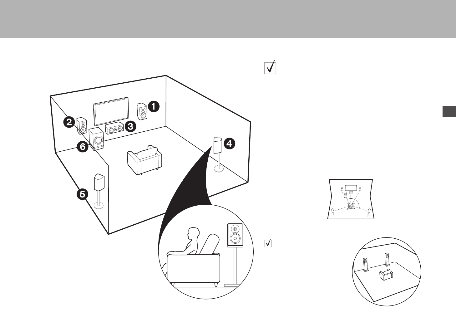
3
> Antes de empezar >Conexión > Configuración > Reproducción > Nombres de las piezas
Es
Paso 1: Elija la disposición de los altavoces
12
Altavoces delanteros
3
Altavoz central
45
Altavoces envolventes
6
Subwoofer con fuente de alimentación propia
Para un sistema de 5.1 canales
Este es un sistema de 5.1 canales que es el sistema envolvente básico. Los
altavoces delanteros emiten sonidos delanteros en estéreo y el altavoz central
emite sonidos centrales como diálogos y voces. Los altavoces de sonido
envolvente crean un campo de sonido trasero. El subwoofer con fuente de
alimentación propia reproduce sonidos bajos y crea un campo de sonido rico. Los
altavoces delanteros deberían colocarse a la altura de la oreja, mientras que los
altavoces envolventes deberían ubicarse justo por encima de la altura de la oreja.
El altavoz central debería instalarse orientado hacia la posición de audición.
Coloque el subwoofer con fuente de alimentación propia orientado al frente.
Colocándolo entre el altavoz central y el altavoz delantero produce un sonido
natural incluso cuando se reproduce música.
0
Los altavoces delanteros, el altavoz central y los altavoces envolventes
cuentan como 5 canales y el subwoofer con alimentación propia cuenta como
0.1 de un canal, lo que nos da el nombre del sistema de 5.1 canales.
Ir a "Conexión" (
P9)
* 1: 22e a 30e, * 2: 120e
Sistema de altavoces B:
En un sistema de 5.1 canales, puede conectar un
set más de altavoces delanteros para usarlos
como sistema de altavoces B. En este caso, el
sistema de 5.1 canales se convierte en el sistema
de altavoces A y puede elegir que el mismo audio
se emita desde A, B, o A+B. Tenga en cuenta que
no se emite sonido desde el altavoces B cuando
se utiliza Zone Speaker (
P17).
Ir a "Conexión" (
P9)
*
1
*
2
SN29402194_VSX-301_BAS_Es.book 3 ページ 2016年1月6日 水曜日 午前12時13分

4
> Antes de empezar >Conexión > Configuración > Reproducción > Nombres de las piezas
16
(
P3)
78
Altavoces traseros envolventes
Para un sistema de 7.1 canales (con
altavoces traseros envolventes)
Este es un sistema con altavoces traseros envolventes que se añaden al sistema de 5.1 canales
básico. La conexión de los altavoces traseros envolventes mejora la sensación de envolvimiento y
conectividad de sonido creada por el campo de sonido trasero y proporciona un campo sonoro más
real. Cuando el formato de entrada es Dolby Atmos, puede seleccionar el modo de audición Dolby
Atmos, que proporciona el sonido envolvente 3D más actualizado. Con otros formatos que no sean
Dolby Atmos, aún puede crear un campo de sonido emitiendo el sonido desde los altavoces traseros
envolventes cuando selecciona el modo de audición Dolby Surround. En una disposición óptima, los
altavoces traseros envolventes están a la altura de la oreja. Coloque los altavoces envolventes en una
posición ligeramente más delantera de lo que haría en un sistema de 5.1 canales.
0
Si incluye altavoces traseros envolventes en la configuración, se necesitan altavoces envolventes.
Ir a "Conexión" (
P9)
* 1: 22e a 30e, * 2: 90e a 110e, * 3: 135e a 150e
Sistema de altavoces B:
En un sistema de 7.1 canales (con altavoces
traseros envolventes), puede conectar un set
más de altavoces delanteros para usarlos
como sistema de altavoces B. En este caso, el
sistema de 7.1 canales se convierte en el
sistema de altavoces A y puede elegir que el
mismo audio se emita desde A, B, o A+B.
Tenga en cuenta que el sonido no se emite
desde el altavoz envolvente trasero cuando
A+B está seleccionado. Tenga en cuenta que
no se emite sonido desde el altavoces B
cuando se utiliza Zone Speaker (
P17).
Ir a "Conexión" (
P9)
*
2
*
3
*
1
SN29402194_VSX-301_BAS_Es.book 4 ページ 2016年1月6日 水曜日 午前12時13分
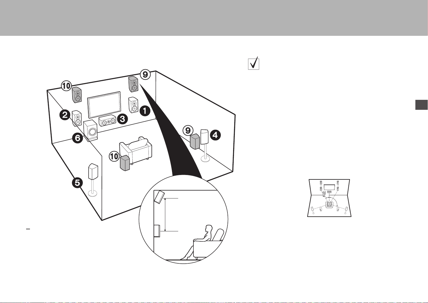
Es
5
> Antes de empezar >Conexión > Configuración > Reproducción > Nombres de las piezas
3´ (0.9 m)
or more
16
(
P3)
9:
Altavoces de altura
Elija uno de los siguientes:
$
$
Altavoces altos delanteros
Altavoces altos traseros
Para un sistema de 7.1 canales
(con altavoces de altura
-A
)
Este es un sistema de 5.1 canales básico al que se añade un altavoz de
altura, como un altavoz alto delantero o trasero. Seleccione qué altavoces
configurar según el entorno de la habitación. Cuando el formato de entrada es
Dolby Atmos, puede seleccionar el modo de audición Dolby Atmos
(reproducción de 5.1.2 canales), que proporciona el sonido envolvente 3D
más actualizado incluyendo sonidos por arriba. Con otros formatos que no
sean Dolby Atmos, aún puede crear un campo de sonido emitiendo el sonido
desde los altavoces de altura cuando selecciona el modo de audición Dolby
Surround. Los altavoces altos delanteros o traseros deberían ubicarse al
menos 0,9 m más altos que los altavoces delanteros. Los altavoces altos
delanteros deberían ubicarse directamente por encima de los altavoces
delanteros y la distancia entre los altavoces altos traseros debería ser igual a
la distancia entre los altavoces delanteros. Ambos deberían instalarse
orientados hacia la posición de audición.
Ir a "Conexión" (
P10)
* 1: 22e a 30e, * 2: 120e
*
1
*
2
SN29402194_VSX-301_BAS_Es.book 5 ページ 2016年1月6日 水曜日 午前12時13分

6
> Antes de empezar >Conexión > Configuración > Reproducción > Nombres de las piezas
16
(
P3)
9:
Altavoces de altura
Elija uno de los siguientes:
$
$
$
Altavoces delanteros superiores
Altavoces medios superiores
Altavoces traseros superiores
Para un sistema de 7.1 canales
(con altavoces de altura
-B
)
Este es un sistema de 5.1 canales básico al que se añaden por ejemplo
altavoces de techo, como altavoces delanteros superiores, altavoces medios
superiores o altavoces traseros superiores. Seleccione qué altavoces
configurar según el entorno de la habitación. Cuando el formato de entrada es
Dolby Atmos, puede seleccionar el modo de audición Dolby Atmos
(reproducción de 5.1.2 canales), que proporciona el sonido envolvente 3D
más actualizado incluyendo sonidos por arriba. Con otros formatos que no
sean Dolby Atmos, aún puede crear un campo de sonido emitiendo el sonido
desde los altavoces de altura cuando selecciona el modo de audición Dolby
Surround. Ponga los altavoces delanteros superiores en el techo orientados
hacia la posición de asiento, los altavoces medios superiores directamente
encima de la posición de asiento, y los altavoces traseros superiores en el
techo detrás de la posición de asiento. La distancia entre cada par debería ser
igual a la distancia entre los dos altavoces delanteros.
0 Dolby Laboratories recomienda colocar este tipo de altavoces de altura
para conseguir el mejor efecto Dolby Atmos.
Ir a "Conexión" (
P10)
* 1: 30e a 55e, * 2: 65e a 100e, * 3: 125e a 150e
*
1
*
2
*
3
SN29402194_VSX-301_BAS_Es.book 6 ページ 2016年1月6日 水曜日 午前12時13分
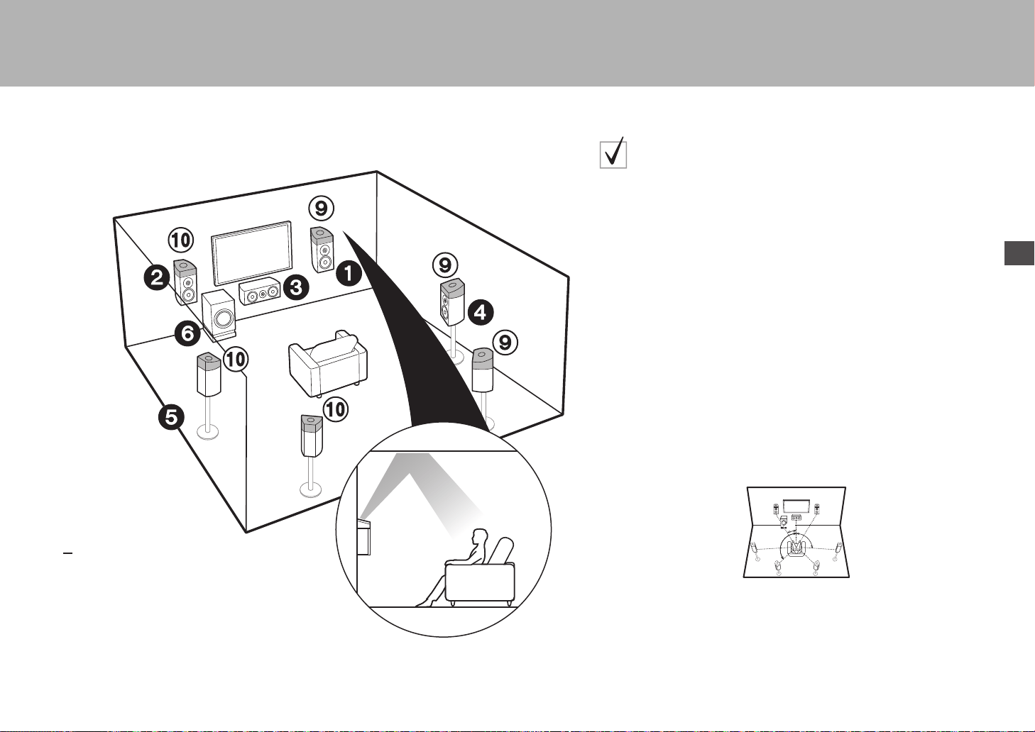
Es
7
> Antes de empezar >Conexión > Configuración > Reproducción > Nombres de las piezas
16
(
P3)
9:
Altavoces de altura
Elija uno de los siguientes:
$
$
$
Altavoces habilitados con Dolby (frontales)
Altavoces habilitados con Dolby (envolventes)
Altavoces habilitados con Dolby (envolventes traseros)
Para un sistema de 7.1 canales
(con altavoces de altura
-C
)
Este es un sistema de 5.1 canales básico que usa altavoces habilitados con
Dolby al que se añaden altavoces de altura, como altavoces (delanteros)
habilitados con Dolby o altavoces (envolventes) habilitados con Dolby o
altavoces (envolventes traseros) habilitados con Dolby. Seleccione qué
altavoces configurar según el entorno de la habitación. Los altavoces
habilitados con Dolby son altavoces especiales diseñados para estar
orientados hacia el techo de modo que el sonido se escuche tras rebotar
contra el techo y así parezca que el sonido viene de arriba. Cuando el formato
de entrada es Dolby Atmos, puede seleccionar el modo de audición Dolby
Atmos (reproducción de 5.1.2 canales), que proporciona el sonido envolvente
3D más actualizado incluyendo sonidos por arriba. Con otros formatos que no
sean Dolby Atmos, aún puede crear un campo de sonido emitiendo el sonido
desde los altavoces de altura cuando selecciona el modo de audición Dolby
Surround. Colóquelos encima de los altavoces delanteros o encima de los
altavoces envolventes o de los altavoces envolventes traseros. Si se trata de
altavoces habilitados con Dolby integrados, póngalos en lugar de los
altavoces delanteros, los altavoces envolventes o los altavoces envolventes
traseros.
Ir a "Conexión" (
P10)
* 1: 22e a 30e, * 2: 90e a 120e, * 3: 135e a 150e
*
1
*
2
*
3
SN29402194_VSX-301_BAS_Es.book 7 ページ 2016年1月6日 水曜日 午前12時13分

8
> Antes de empezar >Conexión > Configuración > Reproducción > Nombres de las piezas
12
Altavoces delanteros (Biamplificación)
3
Altavoz central
45
Altavoces envolventes
6
Subwoofer con fuente de alimentación propia
Para biamplificar los altavoces
Es posible conectar altavoces delanteros compatibles con biamplificación
para mejorar la calidad de los tonos graves y agudos. El número máximo de
canales disponibles con esta conexión es 5.1 porque los altavoces de
biamplificación requieren un amplificador para los conectores del tweeter y un
amplificador para los conectores del woofer. Los efectos y ubicaciones para
los altavoces son los mismos que en el esquema de 5.1 canales que no usa
altavoces de biamplificación.
Ir a "Conexión" (
P11)
* 1: 22e a 30e, * 2: 120e
*
1
*
2
SN29402194_VSX-301_BAS_Es.book 8 ページ 2016年1月6日 水曜日 午前12時13分
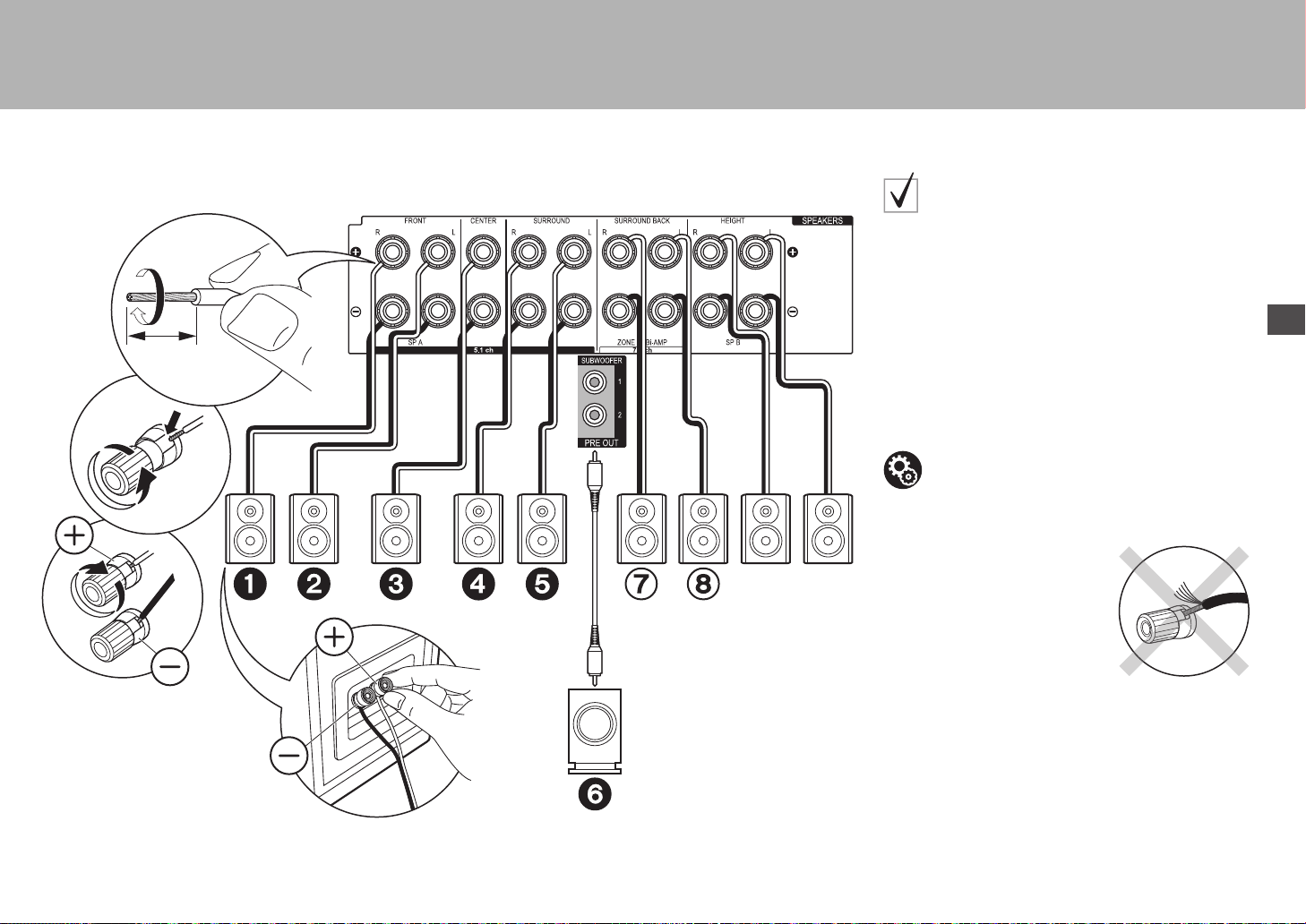
9
> Antes de empezar >Conexión > Configuración > Reproducción > Nombres de las piezas
Es
Paso 2: Conexión de los altavoces
2
1
1/2˝
(12 mm)
Speaker B
1 Cable de altavoz, 2 Cable de subwoofer
en caso de:
Páginas de 3 a 4
Conecte 123456 para un sistema de 5.1 canales.
Con un sistema de 7.1 canales (con altavoces
envolventes traseros), conecte también 7 y 8. Se
pueden conectar hasta dos subwoofers con fuente de
alimentación propia. Se emite la misma señal desde cada
uno de los conectores SUBWOOFER. Con esta conexión,
puede conectar un set más de altavoces delanteros para
usarlos como sistema de altavoces B. Cambie los
altavoces A/B con el ajuste AV (
P25). Tenga en cuenta
que no se emite sonido desde el altavoz envolvente
trasero cuando A+B está seleccionado.
Asegúrese de que los cables expuestos de los altavoces no
sobresalgan de los terminales de los altavoces al conectarlos. Si
los cables expuestos de los altavoces tocan el panel trasero o los
cables + y – se tocan entre sí, el circuito de protección se activará.
Configuración
0 Es necesario realizar ajustes para la
configuración de los altavoces que ha conectado
en "1. MCACC totalmente automático" (
P19) en
Initial Setup.
SN29402194_VSX-301_BAS_Es.book 9 ページ 2016年1月6日 水曜日 午前12時13分
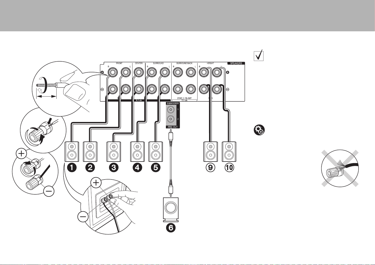
10
> Antes de empezar >Conexión > Configuración > Reproducción > Nombres de las piezas
2
1
1/2˝
(12 mm)
1 Cable de altavoz, 2 Cable de subwoofer
en caso de:
Páginas de 5 a 7
Conecte 1234569:. Se pueden conectar hasta
dos subwoofers con alimentación propia. Se emite la
misma señal desde cada uno de los conectores
SUBWOOFER.
0 Aparte de estas conexiones, también puede conectar
unos altavoces envolventes traseros 7 y 8. Sin
embargo, solo puede emitir audio desde un set de 78
o 9: a la vez. Cuando ambos están conectados,
puede seleccionar qué altavoces priorizar con el ajuste
AV (
P25).
Asegúrese de que los cables expuestos de los altavoces no
sobresalgan de los terminales de los altavoces al conectarlos. Si
los cables expuestos de los altavoces tocan el panel trasero o los
cables + y – se tocan entre sí, el circuito de protección se activará.
Configuración
0 Es necesario realizar ajustes para la
configuración de los altavoces que ha conectado
en "1. MCACC totalmente automático" (
P19) en
Initial Setup.
SN29402194_VSX-301_BAS_Es.book 10 ページ 2016年1月6日 水曜日 午前12時13分
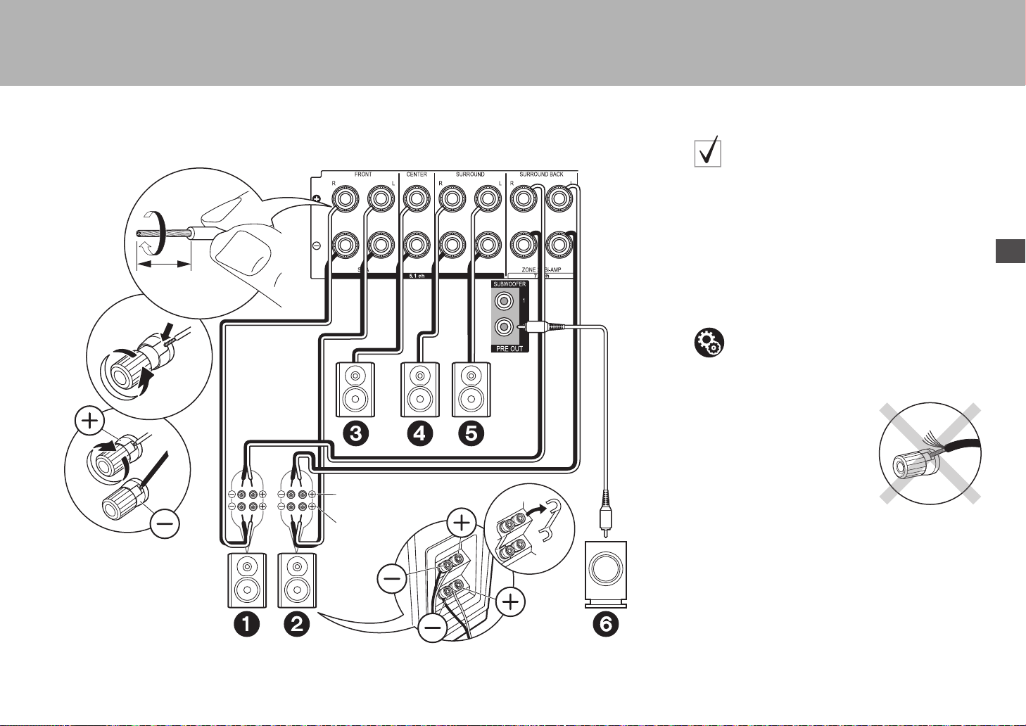
11
> Antes de empezar >Conexión > Configuración > Reproducción > Nombres de las piezas
Es
1
2
1/2˝
(12 mm)
Para alta
frecuencia
Para baja
frecuencia
1 Cable de altavoz, 2 Cable de subwoofer
en caso de:
Página 8
Conecte los altavoces delanteros compatibles con la
conexión de biamplificación a los conectores FRONT y
SURROUND BACK. Asegúrese de quitar el puente
encajado entre los conectores del woofer y los conectores
del tweeter de los altavoces delanteros. En caso de
conexión Bi-Amp, consulte el manual de instrucciones de
sus altavoces. Se pueden conectar hasta dos subwoofers
con alimentación propia. Se emite la misma señal desde
cada uno de los conectores SUBWOOFER.
Asegúrese de que los cables expuestos de los altavoces no
sobresalgan de los terminales de los altavoces al conectarlos. Si
los cables expuestos de los altavoces tocan el panel trasero o los
cables + y – se tocan entre sí, el circuito de protección se activará.
Configuración
0 La conexión de biamplificación requiere que
cambie algunos ajustes. Seleccione "Yes" en "Bi-
Amp" en "1. MCACC totalmente automático"
(
P19) en la Initial Setup.
SN29402194_VSX-301_BAS_Es.book 11 ページ 2016年1月6日 水曜日 午前12時13分
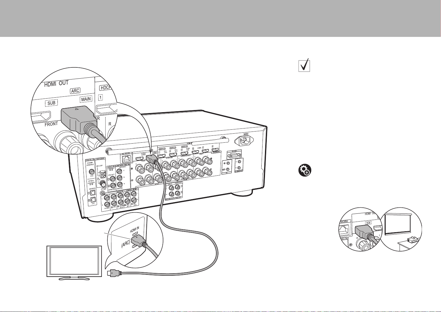
12
> Antes de empezar >Conexión > Configuración > Reproducción > Nombres de las piezas
Paso 3: Conexión del TV
HDMI IN (ARC)
1
TV
1 Cable HDMI
Si tiene:
ARC TV
Esta unidad se conecta entre su TV y los componentes
AV. Si conecta dos o más componentes AV, cambiando el
selector de entrada puede seleccionar el vídeo
visualizado en el TV y la salida de audio desde esta
unidad.
Aquí se muestran las conexiones para un TV compatible
con la función ARC (Canal de retorno de audio).
Realizando la conexión con un único cable HDMI, no solo
puede transmitir al TV la entrada de vídeo a esta unidad,
sino que también puede reproducir el sonido del TV a
través de esta unidad.
Elija un conector HDMI IN en el TV compatible con ARC
al realizar la conexión.
Se puede conectar otro TV o proyector al conector HDMI OUT
SUB. Este conector no es compatible con ARC. Para información
sobre cómo transmitir el vídeo a un dispositivo conectado (P21)
Configuración
0 Para usar la función ARC se requieren algunos
ajustes. Seleccione "Yes" en "5. Canal de retorno
de audio" (
P20) en la Initial Setup.
0 Consulte el manual de instrucciones de la TV
para indicaciones sobre sus conexiones y
configuración.
SN29402194_VSX-301_BAS_Es.book 12 ページ 2016年1月6日 水曜日 午前12時13分
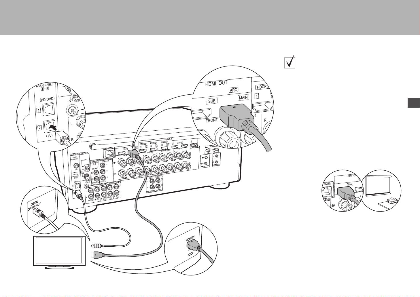
13
> Antes de empezar >Conexión > Configuración > Reproducción > Nombres de las piezas
Es
TV
12
1 Cable HDMI, 2 Cable óptico digital
Si tiene:
TV no ARC
Esta unidad se conecta entre su TV y los componentes
AV. Si conecta dos o más componentes AV, cambiando el
selector de entrada puede seleccionar el vídeo
visualizado en el TV y la salida de audio desde esta
unidad.
Se describen las conexiones para una TV no compatible
con la función ARC (Canal de retorno de audio).
Realizando la conexión con un cable HDMI y un cable
óptico digital, no solo puede transmitir al TV la entrada de
vídeo a esta unidad, sino que también puede reproducir el
sonido del TV a través de esta unidad.
0 La conexión con un cable óptico digital no es necesaria
si va a ver el TV mediante un dispositivo como una caja
descodificadora de cable (es decir, sin usar el
sintonizador integrado en el TV).
Se puede conectar otro TV o proyector al conector HDMI OUT
SUB. Este conector no es compatible con ARC. Para información
sobre cómo transmitir el vídeo a un dispositivo conectado (P21)
SN29402194_VSX-301_BAS_Es.book 13 ページ 2016年1月6日 水曜日 午前12時13分
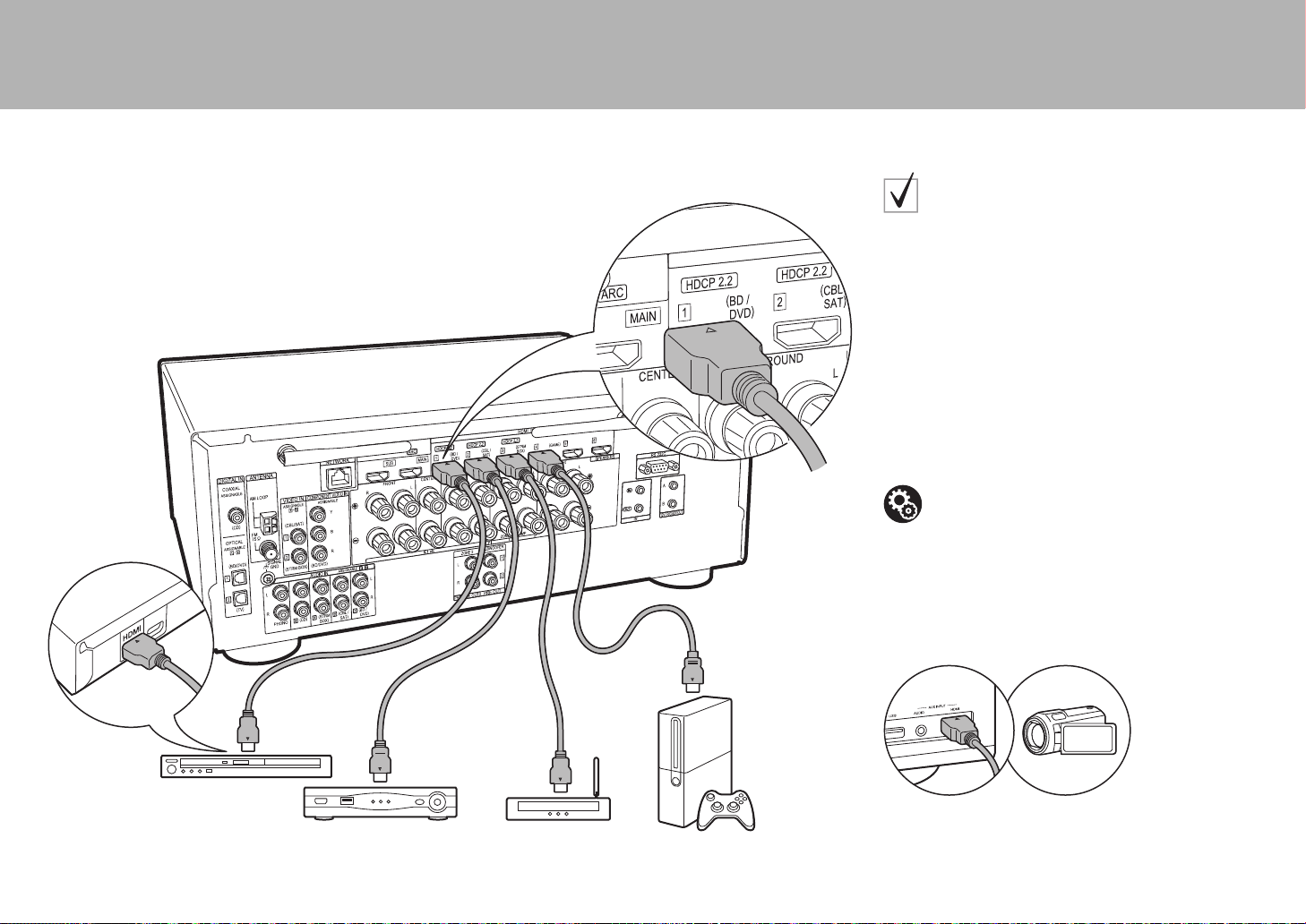
14
> Antes de empezar >Conexión > Configuración > Reproducción > Nombres de las piezas
Paso 4: Conexión de los componentes AV
BD/DVD
GAME
1
Decodificador de
cable/satélite
Reproductor multimedia
de flujo de datos continuo
1 Cable HDMI
Si tiene:
Componentes AV HDMI
Este es un ejemplo de conexión con un componente AV
que cuenta con un conector HDMI. Con la conexión a un
componente AV que cumpla con el estándar CEC
(Consumer Electronics Control), puede usar funciones
como la función HDMI CEC que vincula con el selector de
entrada, y la función HDMI Standby Through que le
permite reproducir vídeo y audio desde componentes AV
en el TV incluso cuando esta unidad está en modo de
espera.
0 Para reproducir vídeo 4K o 1080p, use un cable HDMI
de alta velocidad. Además, para disfrutar de vídeo
compatible con HDCP2.2, conéctelo a los conectores
HDMI IN1 a IN3.
Puede conectar un dispositivo como una cámara de vídeo al
conector AUX INPUT HDMI del panel frontal.
Configuración
0 Para usar las funciones HDMI CEC y HDMI
Standby Through, es necesaria la configuración
HDMI (
P20). Realice los ajustes después de
haber completado todas las conexiones.
0 Para disfrutar de sonido envolvente digital
incluyendo Dolby Digital, la salida de audio debe
ser ajustada en “Bitstream output” en el
reproductor de discos Blu-ray u otros dispositivos
conectados.
SN29402194_VSX-301_BAS_Es.book 14 ページ 2016年1月6日 水曜日 午前12時13分
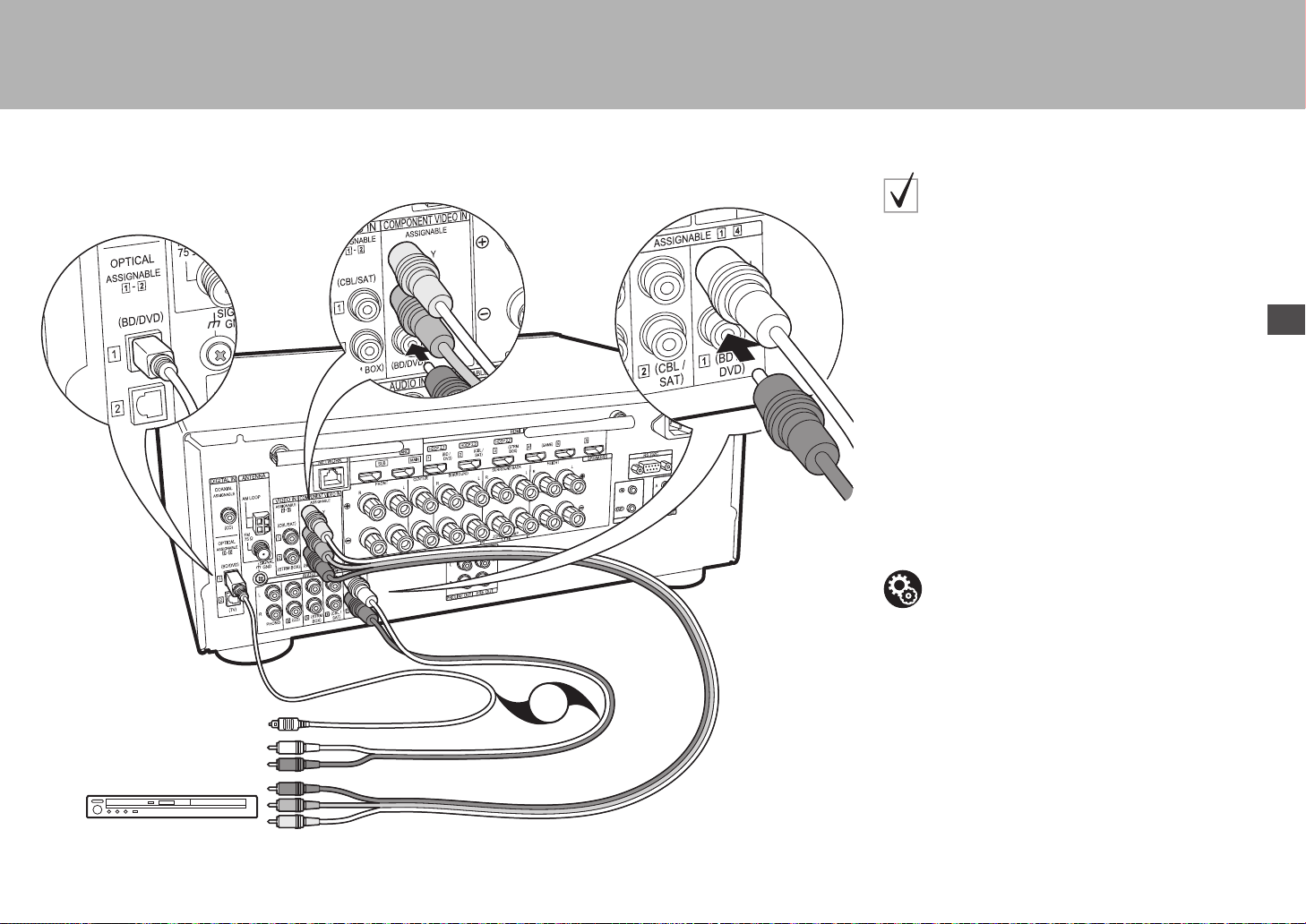
15
> Antes de empezar >Conexión > Configuración > Reproducción > Nombres de las piezas
Es
OR
BD/DVD
1
2
3
1 Cable de vídeo componente, 2 Cable óptico digital, 3 Cable de audio analógico
Si tiene:
Componentes AV no HDMI
Este es un ejemplo de conexión con un componente AV
que no tiene un conector HDMI. Realice las conexiones
con el componente AV para coincidir con los conectores
que este tiene. Cuando la conexión de entrada de vídeo
se hace en el conector BD/DVD, la conexión de entrada
de audio también debería hacerse en los conectores BD/
DVD, y así sucesivamente, de modo que conecte los
conectores de entrada de vídeo a los conectores con el
mismo nombre que los conectores de entrada de audio.
Tenga en cuenta que la entrada de señales de vídeo al
conector VIDEO IN o a los conectores COMPONENT
VIDEO IN será convertida de forma ascendente a señales
HDMI y, a continuación, será enviada desde el conector
HDMI OUT.
0 Para disfrutar de una reproducción envolvente digital
en formatos como Dolby Digital, es necesario que
realice una conexión para señales de audio con un
cable coaxial digital o un cable óptico digital.
Configuración
0 Los conectores COMPONENT VIDEO IN solo
son compatibles con una resolución 480i o 576i.
Cuando introduzca señales de vídeo a los
conectores COMPONENT VIDEO IN, establezca
la resolución de salida del reproductor en 480i o
576i. Seleccione intercalar si no hay una opción
para 480i, etc. Si su reproductor no es compatible
con una salida de 480i o 576i, utilice el conector
VIDEO IN.
0 Para disfrutar de sonido envolvente digital
incluyendo Dolby Digital, la salida de audio debe
ser ajustada en “Bitstream output” en el
reproductor de discos Blu-ray u otros dispositivos
conectados.
SN29402194_VSX-301_BAS_Es.book 15 ページ 2016年1月6日 水曜日 午前12時13分

16
> Antes de empezar >Conexión > Configuración > Reproducción > Nombres de las piezas
OR
CD
2
1
Tornamesa
1 Cable coaxial digital, 2 Cable de audio analógico
Si tiene:
Componentes de audio
Ejemplo de una conexión con un componente de audio.
Conecte un reproductor de CD utilizando un cable coaxial
digital, o un cable de audio analógico. También puede
conectar una tornamesa que tenga un cartucho de tipo
MM al conector PHONO.
0 Si la tornamesa tiene un ecualizador de audio
integrado, conéctelo a otro conector AUDIO IN.
Además, si la tornamesa usa un cartucho de tipo MC,
instale un ecualizador de audio compatible con el
cartucho de tipo MC entre la unidad y el tocadiscos,
después conéctelo a cualquier conector AUDIO IN
excepto al conector PHONO.
Si la tornamesa tiene un cable de toma a tierra, conéctelo al
terminal SIGNAL GND de esta unidad.
SN29402194_VSX-301_BAS_Es.book 16 ページ 2016年1月6日 水曜日 午前12時13分
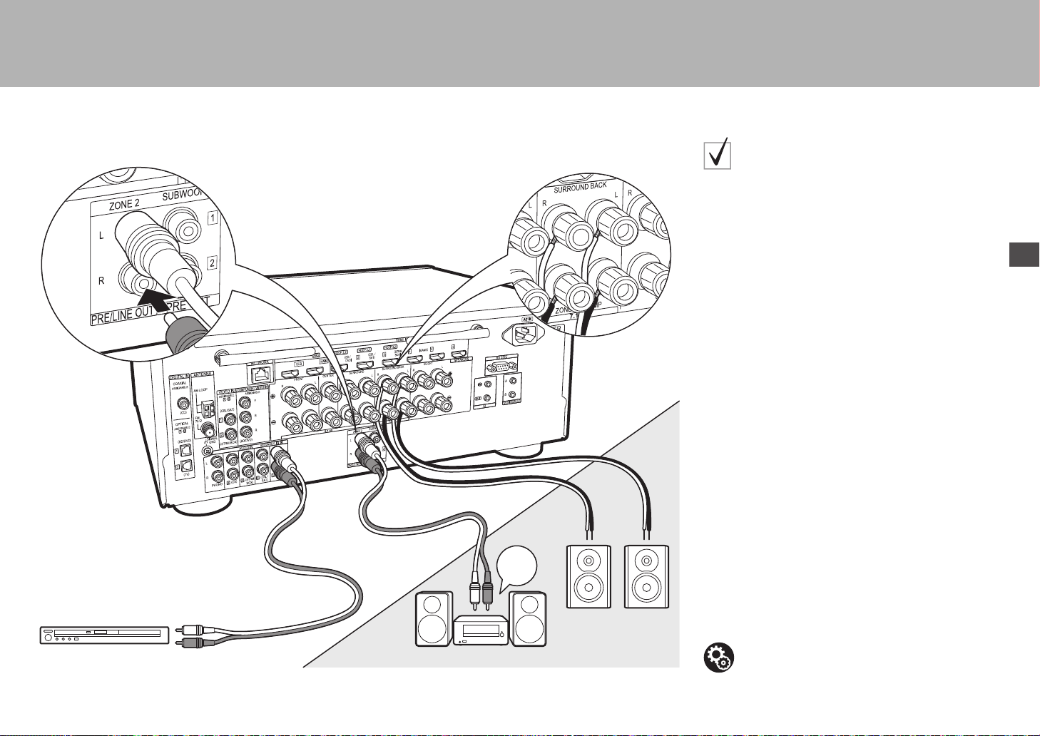
17
> Antes de empezar >Conexión > Configuración > Reproducción > Nombres de las piezas
Es
BD/DVD
ZONE2 PRE/LINE OUT
ZONE SPEAKER
1
2
ZONE2
LINE
IN
MAIN ROOM
1 Cable de audio analógico, 2 Cable de altavoz
Conexión multizona
Puede disfrutar de audio en otra habitación, por ejemplo,
reproduciendo un reproductor de discos Blu-ray en la
habitación principal (en la que está ubicada esta unidad) y
escuchando la radio por internet en la otra habitación
(ZONE 2).
0 Las señales de audio DSD y Dolby TrueHD no se
transmiten a la ZONE 2 cuando están seleccionadas
con el selector de entrada "NET".
Conexiones con un componente AV
Cuando se envía el audio de un componente AV externo
a la ZONE 2, tiene que realizar una conexión usando un
cable de audio analógico.
ZONE 2 PRE/LINE OUT
Es posible reproducir una fuente de 2 canales en otra
habitación mientras reproduce una fuente de 7.1 canales
en la habitación principal. Conecte las conexiones ZONE
2 PRE/LINE OUT de la unidad y las conexiones de LINE
IN del preamplificador principal o del amplificador de
potencia en otra habitación con un cable de audio
analógico.
ZONE SPEAKER
Es posible conectar los altavoces en otra habitación y
reproducir fuentes de 2 canales.
0 Puede reproducir a través de un máximo de 5.1
canales en la habitación principal durante la
reproducción en ZONE 2. Los modos de audición
como los modos Dolby Atmos no se pueden
seleccionar.
0 Tenga en cuenta que no se emite sonido desde el
altavoces B cuando se utiliza Zone Speaker.
Configuración
0 Para disfrutar de esta función, se requieren
ajustes en Initial Setup, "4. Configuración de
multizona" (
P20).
SN29402194_VSX-301_BAS_Es.book 17 ページ 2016年1月6日 水曜日 午前12時13分
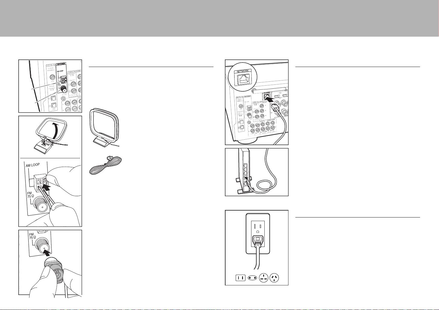
18
> Antes de empezar >Conexión > Configuración > Reproducción > Nombres de las piezas
Paso 5: Conexión de otros cables
Conexión de antenas
Mueva la antena mientras reproduce la radio para
encontrar la posición con mejor recepción. Utilice una
chincheta o similar para fijar la antena FM para interiores a
la pared.
Antena en bucle de AM
Antena de FM para interiores
AM
FM
Conexión de red
Conecte esta unidad a la red usando una LAN con cable o
Wi-Fi (LAN sin cables). Puede disfrutar de funciones de
red como la radio por internet, Music Server y AirPlay
conectando la unidad a la red.
Si realiza la conexión mediante LAN con cable, conecte un
cable Ethernet al puerto NETWORK como se muestra en
la ilustración. Para realizar la conexión mediante Wi-Fi,
después de seleccionar "Wireless" en "3. Conexión de
red" (
P20) en Initial Setup, seleccione el método de
ajuste deseado y siga las instrucciones en pantalla para
configurar la conexión.
Conexión del cable de alimentación
Esta unidad incluye cables de alimentación extraíbles.
Conecte el cable de alimentación a la toma de corriente
después de completar las otras conexiones. Conecte el
cable de alimentación a AC IN de la unidad y luego
conéctelo a la toma. Desconecte siempre el cable de
alimentación del lado de la toma de corriente primero
cuando desconecte el cable de alimentación.
SN29402194_VSX-301_BAS_Es.book 18 ページ 2016年1月6日 水曜日 午前12時13分
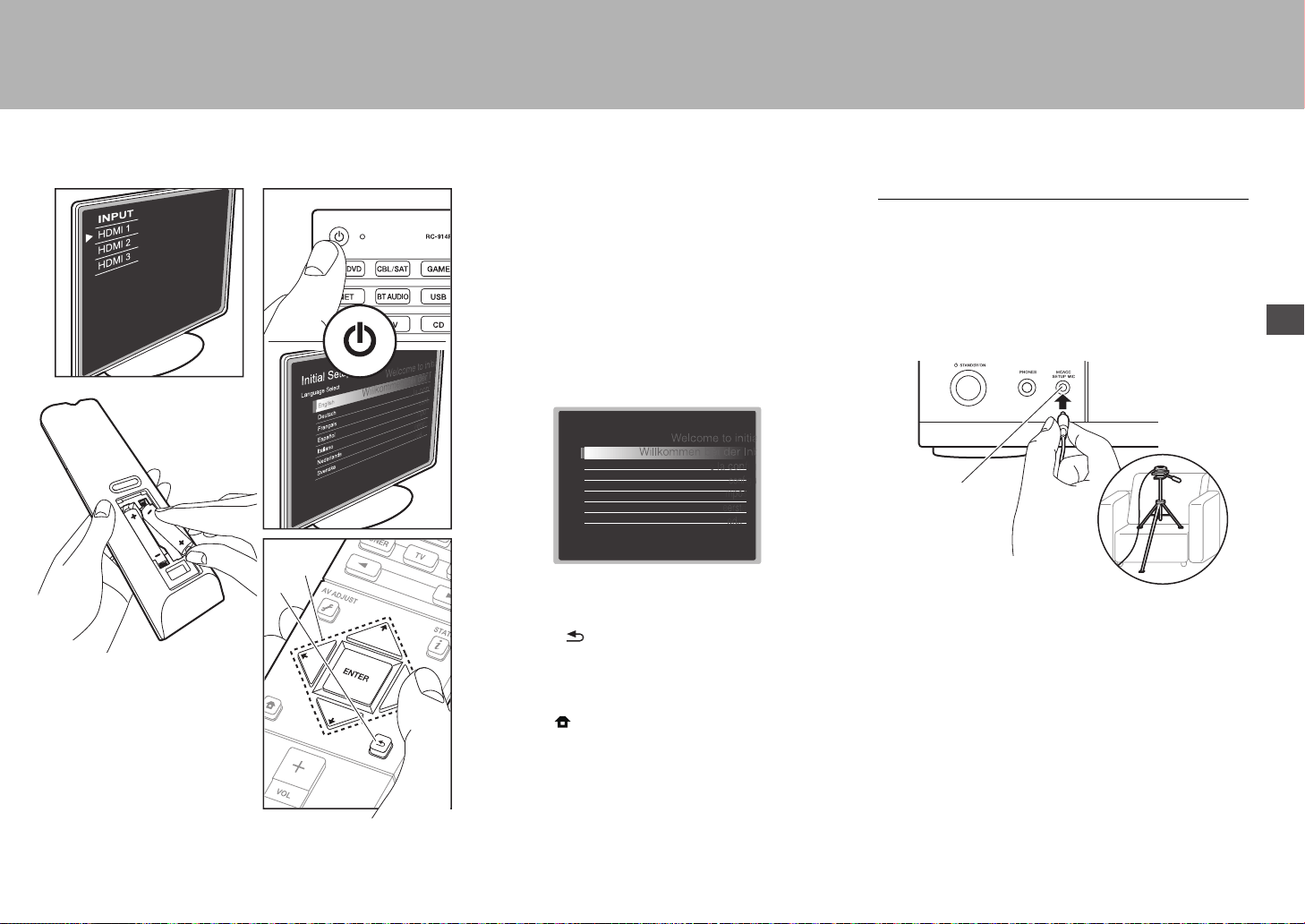
19
> Antes de empezar > Conexión > Configuración > Reproducción > Nombres de las piezas
Es
Paso 6: Encendido y configuración inicial
Initial Setup se inicia automáticamente
Una vez que se hayan completado todas las conexiones,
cambie la entrada del TV a la entrada de esta unidad,
inserte las pilas en el mando a distancia y pulse Í para
encender. Cuando enciende la unidad por primera vez,
Initial Setup se muestra automáticamente en el TV para
permitir que realice los ajustes necesarios para la puesta
en marcha realizando operaciones sencillas siguiendo la
guía en pantalla.
Estas instrucciones le guiarán a través de algunos
elementos que es necesario que compruebe de
antemano. Leer de antemano para que la configuración se
realice sin problemas.
Funcionamiento
Seleccione el elemento con los cursores del mando a
distancia y pulse ENTER (a). Para volver a la pantalla
anterior, pulse (b).
Para rehacer la Initial Setup
Si finaliza el procedimiento durante su curso o desea
cambiar un ajuste realizado durante la configuración
inicial, pulse en el mando a distancia, seleccione
"System Setup" – "Miscellaneous" – "Initial Setup" en
Home, y pulse ENTER.
1. MCACC totalmente automático
Coloque el micrófono de configuración de altavoces
suministrado en la posición de escucha y mida los tonos
de prueba emitidos por los altavoces, a continuación la
unidad establecerá automáticamente el nivel de volumen
óptimo para cada altavoz, las frecuencias de cruce y la
distancia desde la posición de escucha. Esto también
permite la corrección de la distorsión causada por el
ambiente acústico de la habitación.
0 Utilice un trípode o similar para colocar el micrófono de
configuración de altavoces a la altura de la oreja.
0 El sonido del subwoofer puede no ser detectado debido
a que consiste en frecuencias extremadamente bajas.
Establezca el volumen del subwoofer en más de las
mitad.
0 La calibración tarda varios minutos en completarse. Los
altavoces emiten el tono de prueba a alto volumen
durante la medición, de modo que tenga cuidado con el
entorno. Mantenga la habitación en el mayor silencio
posible durante la medición. Si la medición se
interrumpe, apague los electrodomésticos.
a
b
Initial Setup
Language Select
English
Deutsch
Français
Español
Italiano
Nederlands
Svenska
MCACC
SETUP MIC
SN29402194_VSX-301_BAS_Es.book 19 ページ 2016年1月6日 水曜日 午前12時13分
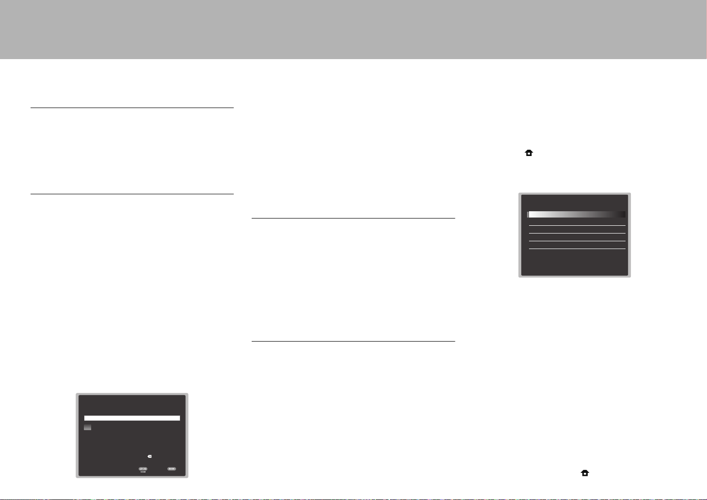
20
> Antes de empezar > Conexión > Configuración > Reproducción > Nombres de las piezas
2. Configuración de fuente
Compruebe que cada fuente de entrada está conectada
correctamente. Siga la guía, seleccione la entrada que
quiere confirmar, inicie la reproducción del reproductor
seleccionado y confirme que las imágenes aparecen en el
TV y que se reproduce el sonido.
3. Conexión de red
Configure la conexión Wi-Fi con un punto de acceso tal
como un enrutador de LAN inalámbrico. Existen los
siguientes dos métodos de conexión por Wi-Fi:
"Scan Networks":
Busque un punto de acceso desde esta
unidad. Entérese del SSID del punto de acceso de antemano.
"Use iOS Device (iOS7 or later)": Comparta los ajustes
de Wi-Fi del dispositivo iOS con esta unidad.
Si selecciona "Scan Networks", existen otras dos posibilidades
más de métodos de conexión. Compruebe lo siguiente.
0 "Enter Password": Introduzca la contraseña (o clave)
del punto de acceso al que conectarse.
0 "Push Button": Si el punto de acceso tiene un botón de
conexión automática, puede conectarse sin introducir
una contraseña.
0 Si no se muestra el SSID del punto de acceso, en la
pantalla del listado de SSIDs seleccione "Other..." con el
cursor del mando a distancia y pulse ENTER,
después siga las instrucciones en pantalla.
Entrada de teclado
Para cambiar entre mayúsculas y minúsculas, seleccione
"A/a"
en la pantalla
y pulse ENTER. Para seleccionar si
enmascarar la contraseña con "*" o mostrarla en texto sin
formato, pulse +Fav en el mando a distancia. Pulse CLEAR
para borrar todos los caracteres introducidos.
0 Durante el ajuste de red se visualiza una ventana de
confirmación pidiéndole aceptar la política de privacidad.
Seleccione "Yes" y pulse ENTER para indicar su
conformidad.
4. Configuración de multizona
Establezca el método de salida de audio en la ZONE 2
cuando quiera emitir audio para disfrutarlo en una
habitación separada de la habitación principal. Si ha
conectado altavoces en otra habitación con un cable de
altavoz, seleccione "Using AV Receiver". Se ha conectado
un preamplificador principal en otra habitación con un cable
de audio analógico, seleccione "with External Premain
Amplifier". Si ha conectado un amplificador de potencia,
seleccione "with External Power Amplifier".
5. Canal de retorno de audio
Si ha conectado un TV compatible con ARC, seleccione
"Yes". El ajuste ARC de esta unidad se activa y puede
escuchar el audio del TV a través de esta unidad.
Wi-Fi Setup
SSID
When finished, select the "OK" key.
**
OKA/a
a b cdef gh i jklm
nopqr s tuvwxy z
1 2 3456789 0-^ \
,./;:@[]
A/aAll Erase
Configuración HDMI
HDMI CEC
Realice este ajuste para habilitar la función de control para
dispositivos que cumplen con el estándar CEC. Este está
establecido automáticamente en activado si ha
seleccionado "Yes" en "5. Canal de retorno de audio" en la
Initial Setup.
Pulse el botón del mando a distancia para establecer
"System Setup" – "Hardware" – "HDMI" – "HDMI CEC" en
"On" en la pantalla del TV. Habilite también la función de
control CEC en el dispositivo CEC que ha conectado.
HDMI Standby Through
Las señales de entrada desde los componentes AV se transmiten
al TV incluso si esta unidad está en modo de espera
0
"Auto" / "Auto (Eco)":
Seleccione uno de estos ajustes
cuando los componentes AV conectados cumplen el
estándar CEC. Independientemente del selector de entrada
seleccionado inmediatamente antes de cambiar la unidad al
modo de espera, puede transmitir señales de entrada
desde componentes AV al TV. Seleccione "Auto (Eco)" si el
TV también cumple con el estándar CEC. Puede reducir el
consumo de energía en el modo de espera.
0
"Nombres del selector de entrada para BD/DVD,
etc.":
Puede transmitir las señales de entrada desde el
selector de entrada establecido al TV. Se puede seleccionar
cuando "HDMI CEC" está establecido en "Off".
0 "Last": Puede transferir las señales de entrada del
selector de entrada seleccionado inmediatamente antes
de que la unidad se cambiase al modo de espera. Se
puede seleccionar cuando "HDMI CEC" está establecido
en "Off".
Para salir de los ajustes, pulse .
HDMI
HDMI CEC
HDMI Standby Through
Audio TV Out
Audio Return Channel
Auto Delay
On
Auto(Eco)
Auto
Auto
On
SN29402194_VSX-301_BAS_Es.book 20 ページ 2016年1月6日 水曜日 午前12時13分
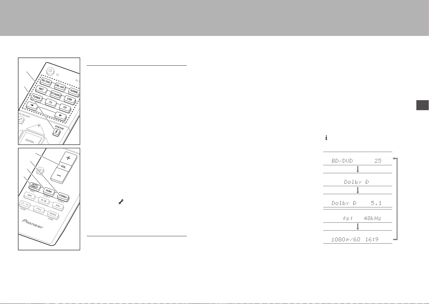
21
> Antes de empezar > Conexión > Configuración > Reproducción > Nombres de las piezas
Es
Reproducción básica
Reproducción de componente AV
1. Cambie la entrada en la TV a aquella
asignada a la unidad.
2. Pulse el selector de entrada (a) en el mando
a distancia con el mismo nombre que el
conector al que ha conectado el reproductor
para cambiar la entrada.
Por ejemplo, pulse BD/DVD para reproducir
el reproductor conectado al conector BD/
DVD. Pulse TV para escuchar el sonido de la
TV.
También puede seleccionar la entrada con
los botones 21.
0 Cuando la función de vínculo CEC está en
funcionamiento, la entrada cambia
automáticamente cuando ha conectado un
TV que cumple con el estándar CEC y un
reproductor a esta unidad usando una
conexión HDMI.
3. Inicie la reproducción en el reproductor.
4. Utilice VOL+/– (b) para ajustar el volumen.
Cuando un TV está conectado al conector
HDMI OUT SUB
Pulse el botón en el mando a distancia para
ver el AV Adjust y establezca "Other" – "HDMI
Out" en "SUB" o "MAIN+SUB".
Modo de audición
Esta unidad está equipada con una variedad de
modos de audición. Para obtener más
información sobre los modos de audición,
consulte el manual avanzado. Esta sección
presenta alguno de los modos más populares.
0 Se ha planificado una futura actualización de
firmware para permitir que esta unidad sea
compatible con la reproducción en formato de
audio DTS Neural:X. Hasta dicha
actualización, están disponibles Neo:6
Cinema y Neo:6 Music.
Botón AUTO/DIRECT (c)
Puede seleccionar los modos Auto Surround,
Direct y Pure Direct. Según sea el caso, para
las señales de entrada de 2 canales se
selecciona automáticamente el modo Stereo
que sólo reproduce desde los altavoces
delanteros y el subwoofer, y para las señales de
entrada de canales múltiples se seleccionan
automáticamente los modos de audición que
coincide con la señal de entrada, así que Dolby
Digital para las fuentes Dolby Digital, y DTS-HD
Master Audio para DTS-HD Master Audio. El
modo Direct apaga los procesos que pueden
afectar a la calidad del sonido, como las
funciones de control del tono, de modo que
pueda disfrutar de una calidad de sonido aún
mejor. El modo Pure Direct apaga más
procesos que afectan a la calidad del sonido
para una reproducción fiel al sonido original. En
este caso, se desactiva la calibración hecha con
MCACC.
0 Según sean la señal de entrada y la
configuración del altavoz, pueden
seleccionarse automáticamente los modos
Dolby Surround y DTS Neural:X que amplían
la señales de entrada del canal 2 y del 5.1 al
canal 5.1 y 7.1.
Botón SURR (d)
Puede seleccionar una serie de modos de
audición para adecuarlo a su deseo. Existen los
modos Dolby Digital, DTS-HD Master Audio, y
Stereo que pueden ser elegidos para adecuar la
señal de entrada, o bien los modos Dolby
Surround y DTS Neural:X que pueden ampliar
las señales del canal 2 y del 5.1 a los canales
5.1 o 7.1. También puede disfrutar de modos
envolventes originales como los modos
Ext.Stereo y Drama.
Botón STEREO (e)
Puede seleccionar el modo "Stereo" para
reproducir solo desde los altavoces delanteros y
el subwoofer.
El último modo de audición seleccionado para la
fuente se recuerda para cada uno de los
botones AUTO/DIRECT, SURR y STEREO. Si
el contenido que reproduce no es compatible
con el último modo de audición que seleccionó,
se selecciona automáticamente el modo de
audición estándar para el contenido.
Pulse (f) repetidamente para cambiar la
pantalla de la unidad principal en el orden:
f
a
b
c
d
e
SN29402194_VSX-301_BAS_Es.book 21 ページ 2016年1月6日 水曜日 午前12時13分

22
> Antes de empezar > Conexión > Configuración > Reproducción > Nombres de las piezas
Funciones de red
Servicios de red
1. Cambie la entrada en la TV a aquella asignada a la unidad.
2. Pulse NET para ver la pantalla de la lista de servicios de red.
3. Seleccione el elemento con los cursores del mando a
distancia y pulse ENTER para confirmar su selección
(a). Para volver a la pantalla anterior, pulse (b).
Radio por Internet
Cuando esta unidad está conectada a una red, puede escuchar TuneIn u
otros servicios de radio por internet ya registrados. Después de seleccionar el
servicio deseado, siga las instrucciones en pantalla, usando los botones de
cursor para seleccionar las emisoras y los programas de radio y después
pulse ENTER para reproducirlos. La reproducción comienza cuando se
muestra el 100% del almacenamiento temporal.
Music Server
Puede reproducir archivos de música almacenados en PCs o dispositivos
NAS conectados al mismo punto de acceso que esta unidad. Seleccione
el servidor con los cursores, seleccione el archivo de música deseado y
pulse ENTER para iniciar la reproducción. La reproducción comienza
cuando se muestra el 100% del almacenamiento temporal.
Notas:
0
Los servicios de red se vuelven seleccionables una vez que arranca
la red, incluso si no se pueden seleccionar en primer lugar.
0
Puede que se amplíen las funcionalidades mediante actualizaciones
de firmware y que los proveedores de servicios cesen su actividad, lo
que significa que algunos servicios de red y contenidos puede que no
estén disponibles en el futuro. Además, los servicios disponibles
podrían variar dependiendo de su zona de residencia.
a
b
USB
Reproduzca archivos de música desde un dispositivo de
almacenamiento USB.
0 No se puede garantizar el funcionamiento de todos los
dispositivos de almacenamiento USB.
1. Conecte el dispositivo de almacenamiento USB con los
archivos de música en el puerto USB en la parte
delantera de la unidad.
2. Pulse USB en el mando a distancia.
3. Seleccione la carpeta o el archivo de música deseado
con los cursores del mando a distancia y pulse ENTER
para confirmar e iniciar la reproducción (a).
0 Esta unidad puede utilizar dispositivos de
almacenamiento USB que cumplan con los estándares
de la clase de dispositivos de almacenamiento masivo
USB. Esta unidad también es compatible con
dispositivos de almacenamiento USB que usan
formatos de sistemas de archivos FAT16 o FAT32.
a
SN29402194_VSX-301_BAS_Es.book 22 ページ 2016年1月6日 水曜日 午前12時13分
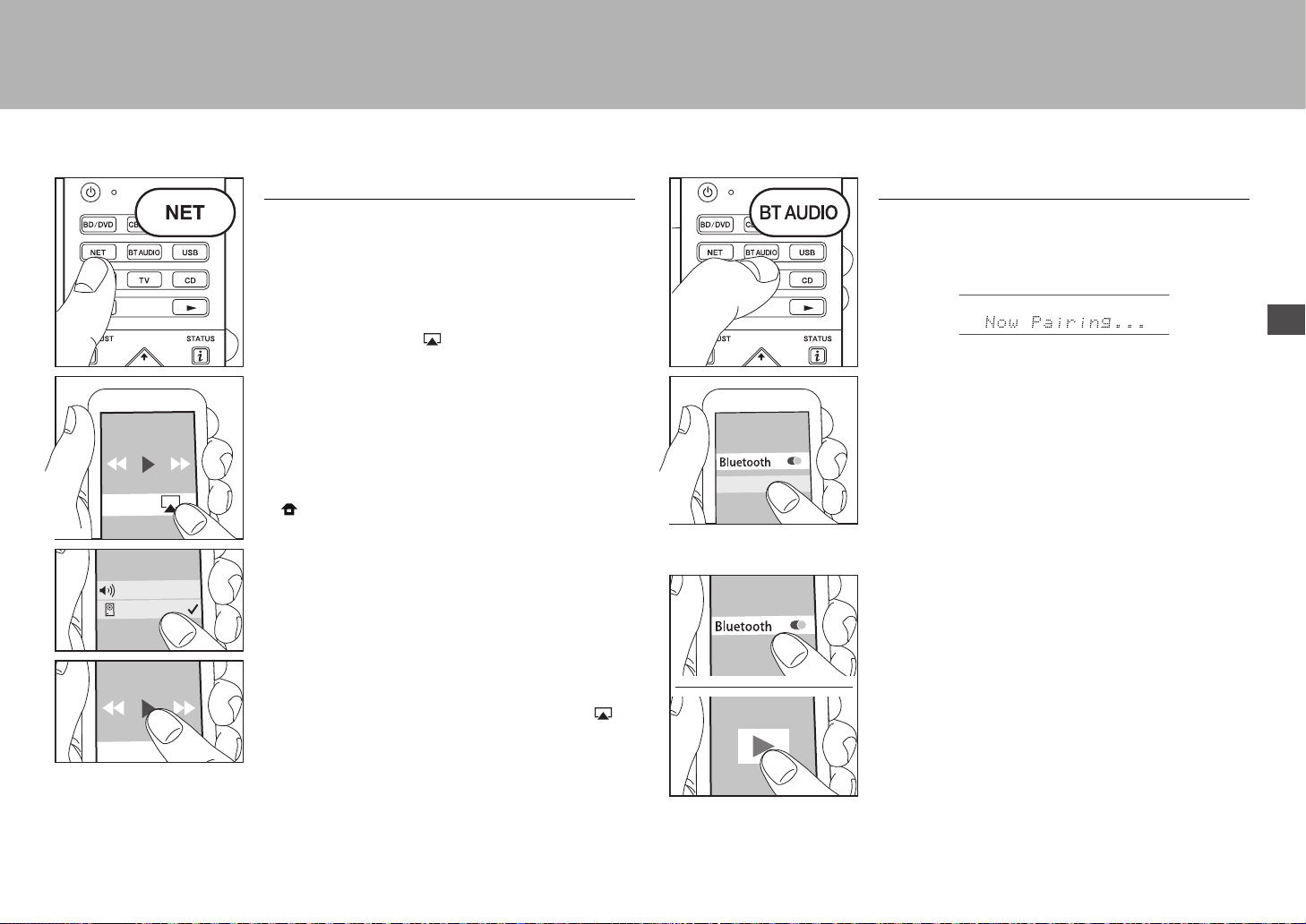
23
> Antes de empezar > Conexión > Configuración > Reproducción > Nombres de las piezas
Es
AirPlay
Puede disfrutar sin cables de los archivos de música
almacenados en un iPhone
®
, iPod touch
®
o iPad
®
conectado al mismo punto de acceso que esta unidad.
0 Actualice la versión de sistema operativo en su
dispositivo iOS a la última versión.
1. Conecte el dispositivo iOS al punto de acceso.
2. Pulse NET.
3. Pulse el icono AirPlay en el centro de control del
dispositivo iOS, seleccione esta unidad de la lista de
dispositivos visualizada y pulse "Done".
4. Reproduzca los archivos de música en el dispositivo
iOS.
0 La función Network Standby está activada por defecto,
de modo que cuando realice los pasos 3 y 4 anteriores,
esta unidad se enciende automáticamente y la entrada
cambia a "NET". Para reducir la cantidad de energía
consumida durante el modo en espera, pulse el botón
del mando a distancia, después en el Home que se
muestra establezca "System Setup" – "Hardware" –
"Power Management" – "Network Standby" en "Off".
0 Debido a las características de la tecnología
inalámbrica AirPlay, el sonido producido en esta unidad
puede quedar ligeramente detrás del sonido
reproducido en el dispositivo con AirPlay activado.
También puede reproducir archivos de música en el
ordenador con iTunes (Ver. 10.2 o posterior). Antes de la
operación, asegúrese de que esta unidad y el PC están
conectados a la misma red, después pulse NET en esta
unidad. A continuación, haga clic en el icono AirPlay en
iTunes, seleccione esta unidad de la lista de dispositivos
mostrada e inicie la reproducción de un archivo de música.
VSX-XXXXX
iPhone
Reproducción BLUETOOTH
®
Emparejado
1. Cuando pulsa BT AUDIO en el mando a distancia, en la
pantalla de esta unidad se muestra "Now Pairing..." y el
modo de emparejamiento se activa.
2. Active (encienda) la función BLUETOOTH del
dispositivo con BLUETOOTH, después seleccione esta
unidad entre los dispositivos mostrados.
Si se le pide una contraseña, introduzca "0000".
0 Para conectar otro dispositivo con BLUETOOTH,
mantenga pulsado BT AUDIO hasta que se muestre
"Now Pairing...", después realice el paso 2 anterior.
Esta unidad puede almacenar la información de hasta 8
dispositivos emparejados.
0 El área de cobertura es de 15 metros (48 pies). Tenga
en cuenta que la conexión con todos los dispositivos
que tengan BLUETOOTH no siempre está garantizada.
Reproducción
1. Cuando la unidad esté encendida, conecte el
dispositivo con BLUETOOTH.
2. El selector de entrada de esta unidad cambiará
automáticamente a "BLUETOOTH".
3. Reproduzca música. Suba el volumen del dispositivo
con BLUETOOTH hasta un nivel adecuado.
0 Debido a las características de la tecnología
inalámbrica BLUETOOTH, el sonido producido en esta
unidad puede llevar un ligero retraso respecto al sonido
reproducido en el dispositivo con BLUETOOTH
activado.
VSX-XXXXX
SN29402194_VSX-301_BAS_Es.book 23 ページ 2016年1月6日 水曜日 午前12時13分
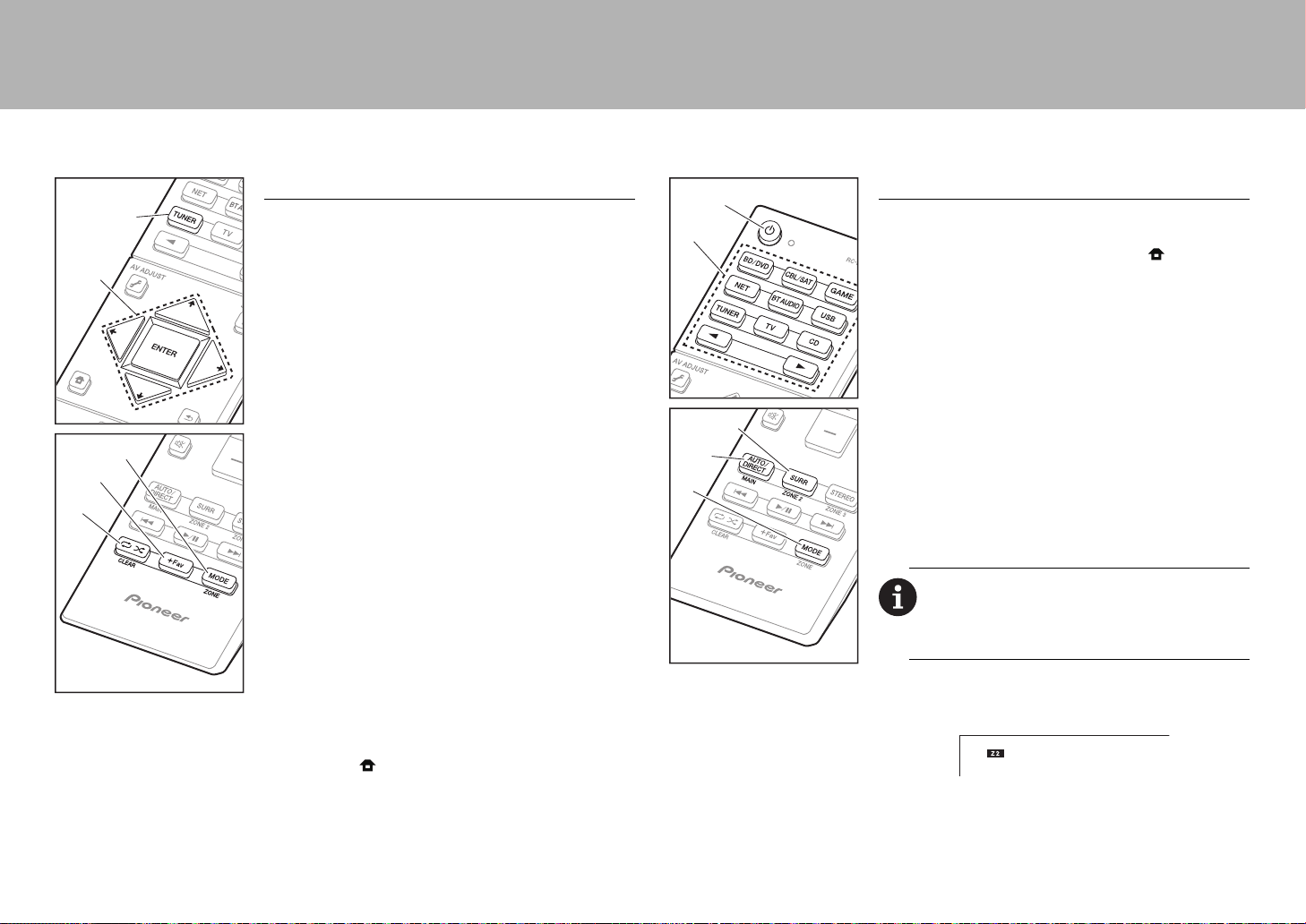
24
> Antes de empezar > Conexión > Configuración > Reproducción > Nombres de las piezas
a
Otros
Escuchar la radio
1. Pulse TUNER (a) del mando a distancia repetidamente
para seleccionar “AM” o “FM” en la pantalla.
2. Pulse MODE (c) del mando a distancia, de modo que el
indicador “TunMode: Auto” de la pantalla se ilumine.
3. Al pulsar los botones de cursor (b) / del mando a
distancia, se inicia la sintonización automática y la
búsqueda se detiene cuando se encuentra una
emisora. Cuando se sintoniza una emisora de radio, el
indicador “TUNED” se enciende en la pantalla.
Puede predefinir hasta 40 emisoras.
1. Sintonice la emisora de radio AM/FM que desea registrar.
2. Pulse +Fav (d) en el mando a distancia de modo que el
número preestablecido parpadee en la pantalla.
3. Mientras que el número preajustado está parpadeando
(unos 8 segundos), pulse repetidamente los botones de
cursor (b) / del mando a distancia para seleccionar
un número entre el 1 y el 40.
4. Pulse +Fav (d) de nuevo en el mando a distancia para
registrar la emisora. Cuando se ha finalizado el registro, el
número preestablecido deja de parpadear. Para
seleccionar una emisora de radio preestablecida, pulse los
botones de cursor (b)
/
en el mando a distancia.
0 Para borrar una emisora preestablecida, pulse los
botones de cursor (b) / del mando a distancia para
seleccionar el número preestablecido que quiere borrar,
pulse +Fav (d) en el mando a distancia y después pulse
CLEAR (e) mientras el número predefinido está
parpadeando. Una vez borrado, el número de la
pantalla se apaga.
Ajuste del paso de frecuencia
Pulse el botón del mando a distancia para seleccionar
"System Setup" – "Miscellaneous" – "Tuner" – "AM/FM
Frequency Step" y elija el paso de frecuencia para su área.
Tenga en cuenta que cuando se cambia este ajuste, se
borran todos los preajustes de radio.
c
d
e
a
b
Multizona
Si no ha hecho los ajustes multizona (
P20) en Initial
Setup, los cambie según sea el método de salida de audio
a otra habitación (ZONE 2). Pulse el botón del mando a
distancia y haga los ajustes en la configuración de sistema
a la cual se accede desde la pantalla de inicio visualizada.
Si ha conectado altavoces en la habitación separada con
un cable de altavoz, seleccione "Zone 2" en "System
Setup" − "Speaker" − "Configuration" − "Zone Speaker".
Si tiene conectado un amplificador de potencia en la
habitación separada con un cable de audio analógico,
entonces ajuste "System Setup" − "Multi Zone" − "Zone
2" − "Output Level" a "Variable" si quiere poder ajustar el
volumen en esta unidad.
Reproducción
1. Mientras mantiene pulsado MODE (a) en el mando a
distancia, pulse ZONE 2 (b) durante 3 o más segundos
hasta que el indicador remoto parpadee dos veces.
0 El controlador remoto cambia al modo para controlar
la ZONE 2.
2. Apunte el mando a distancia hacia la unidad principal y
pulse Í (d).
"Z2" se ilumina en la pantalla de la unidad principal.
3. Pulse el botón del selector de entrada (e) de la entrada
que quiera reproducir en la habitación separada. En la
unidad principal, después de pulsar ZONE 2-
CONTROL, dentro de los siguientes 8 segundos gire el
mando selector de entrada para seleccionar la entrada
Para restablecer el mando a distancia al modo
de control de la habitación principal:
Mientras
mantiene pulsado MODE (a) en el mando a distancia,
pulse MAIN (c) durante 3 o más segundos hasta que el
indicador remoto parpadee una vez.
a
b
c
d
e
SN29402194_VSX-301_BAS_Es.book 24 ページ 2016年1月6日 水曜日 午前12時13分
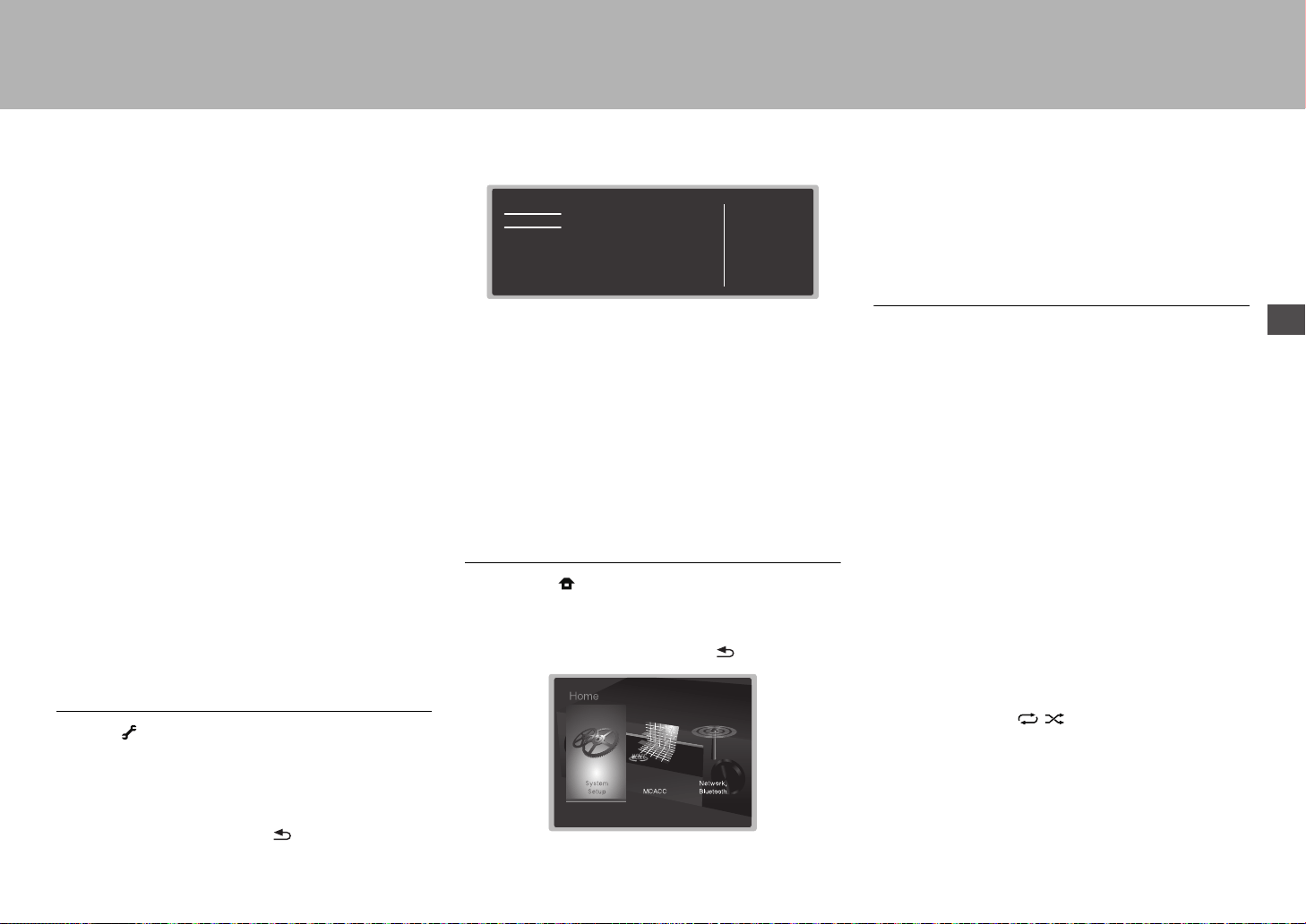
25
> Antes de empezar > Conexión > Configuración > Reproducción > Nombres de las piezas
Es
que quiere reproducir en la otra habitación.
0 Sólo puede seleccionar las mismas entradas para la
habitación principal y la habitación separada con el
selector de entrada "NET" o "BLUETOOTH", o "USB". Si
ha seleccionado "NET" en la habitación principal y luego
selecciona "USB" en la habitación separada, cambia
también a "USB" la habitación principal. No puede
seleccionar diferentes emisoras para la habitación
principal y la habitación separada con la radio AM/FM.
4. Para ajustar el volumen en esta unidad, ajústelo con
VOL+/– en el mando a distancia. Para controlar la
unidad principal, pulse ZONE 2-CONTROL y ajuste con
el control MASTER VOLUME dentro de los siguientes 8
segundos.
0 Si ZONE 2 está activado, el consumo de energía durante
el modo de espera será mayor de lo normal.
Para desactivar la función:
Pulse Í mientras está en el modo para controlar ZONE 2.
O pulse ZONE 2-ON/OFF en la unidad principal.
Reproducción solo en la ZONE 2
Si pone la unidad en modo de espera durante la
reproducción multizona, el indicador Z2 se atenúa y el
modo de reproducción se cambia al modo de reproducción
sólo en una habitación separada. Activar ZONE 2 mientras
esta unidad está en modo de espera también cambiará el
modo de reproducción al mismo ajuste.
AV Adjust
Pulsando en el mando a distancia durante la
reproducción, puede ajustar los ajustes de uso más
frecuente, como el cambio de altavoces y el ajuste de la
calidad del sonido, usando los menús en pantalla.
Seleccione el elemento con los cursores del mando a
distancia y pulse ENTER para confirmar su selección. Para
volver a la pantalla anterior, pulse .
"Tone": Es posible mejorar o moderar los bajos y altos de
los altavoces delanteros. Puede ajustar la calidad del
sonido del amplificador de potencia conectado cuando
enciende ZONE 2.
"Other": Le permite realizar una variedad de ajustes.
0 "Sound Delay": Si el vídeo va por detrás del audio,
puede retrasar el audio para corregir la diferencia.
0 "Sound Retriever": Mejora la calidad del audio
comprimido.
0 "Speakers": Puede cambiar la salida en los altavoces
envolventes traseros y los altavoces de altura y cambiar
la salida para los altavoces A/B.
Inicio
Cuando pulsa en el mando a distancia, se muestra el
menú de inicio y puede realizar ajustes en los diversos
menús. Seleccione el elemento con los cursores del mando
a distancia y pulse ENTER para confirmar su selección.
Para volver a la pantalla anterior, pulse .
"System Setup": Ajustes avanzados para brindarle una
experiencia todavía mejor.
"MCACC": Configure los altavoces automáticamente o
realice los cambios deseados en el ecualizador.
"Network/Bluetooth": Realice los ajustes de conexión Wi-
Fi o los ajustes relacionados con BLUETOOTH.
Cuando la unidad funciona irregularmente
(Restauración de esta unidad)
Reiniciar la unidad puede contribuir a que funcione
correctamente. Para reiniciar la unidad, la ponga en el
modo de espera, después pulse Í STANDBY/ON en la
unidad principal durante al menos 5 segundos. (Los ajustes
de la unidad se mantendrán.) Si no se produce ninguna
mejora incluso después de reiniciar la unidad, pruebe a
desconectar y volver a conectar los cables de alimentación
de la unidad y de los equipos conectados. Si sigue sin
haber mejora, reajustar la unidad al estado en el que se
encontraba en el momento de envío podría solucionar el
problema. Si restablece el estado de la unidad, sus
preferencias serán restablecidas a los valores por defecto.
Apúntelos antes de comenzar el restablecimiento antes de
realizar la siguiente operación.
Cómo restablecer la unidad
1. Mientras mantiene pulsado AUTO/DIRECT en la unidad
principal, pulse Í STANDBY/ON en la unidad principal.
2. "Clear" aparece en la pantalla y la unidad regresa al
modo de espera. No desenchufe el cable de
alimentación hasta que "Clear" desaparezca de la
pantalla.
Para restaurar el mando a distancia, mientras mantiene
pulsado MODE, pulse hasta que el indicador
remoto parpadee dos veces (aproximadamente
3 segundos).
AV Adjust
Tone
Level
MCACC
Other
Bass
Treble
BD/DVD
SN29402194_VSX-301_BAS_Es.book 25 ページ 2016年1月6日 水曜日 午前12時13分

26
> Antes de empezar > Conexión > Configuración > Reproducción > Nombres de las piezas
Panel frontal
1. Mando INPUT SELECTOR: Cambian la entrada a reproducir.
2. Indicador MCACC: Éste se enciende cuando ha activado
la calibración hecha con MCACC.
3. Indicador FL OFF: Éste se enciende cuando ha pulsado
DIMMER repetidamente para apagar la pantalla.
4. Botón DIMMER: Cambia el brillo de la pantalla.
5. Botón ZONE 2-ON/OFF: Desactiva la función multizona.
6. Botón ZONE 2-CONTROL: Controla la función
multizona.
7. Botón HOME MENU: Muestra el Home.
8. Pantalla (
P28)
9. Botones del cursor (botón TUNE / PRESET) y
botón ENTER: Seleccione el elemento con los cursores
y pulse ENTER para confirmar su selección. Cuando use
el TUNER, seleccione la frecuencia con TUNE, o
seleccione emisoras preestablecidas con PRESET.
10.
Indicador NETWORK: Cuando está activada la
alimentación, éste se enciende cuando se selecciona "NET"
con el selector de entrada y la unidad está conectada a la
red. Si la unidad está en el modo de espera, éste se
enciende cuando están activadas las funciones como HDMI
CEC y la espera de red. Sin embargo, no se enciende
cuando está activada la ZONE 2.
11.
Indicador WIRELESS: Se ilumina cuando la unidad está
conectada a la red inalámbrica.
12.
Sensor del mando a distancia
13.
Botón RETURN: Regresa la pantalla al estado anterior.
14.
MASTER VOLUME: Le permite ajustar el volumen.
15.
Botón Í STANDBY/ON: Enciende la unidad o la pone
en modo de espera.
16.
Conector PHONES: Se conectan auriculares estéreo
con una clavija estándar (1/4 pulgadas o ø6,3 mm).
17.
Conector MCACC SETUP MIC: El micrófono para la
configuración de los altavoces suministrado está
conectado.
18.
Botón de modo de audición: Seleccione el modo de
audición.
19.
Botón SOUND RETRIEVER: Activa/desactiva la función
Sound Retriever que proporciona una mejor calidad del
sonido del audio comprimido.
20.
Botón PURE DIRECT: Cambia al modo Pure Direct.
21.
Puerto USB: Un dispositivo de almacenamiento USB
está conectado de manera que los archivos de música
almacenados se pueden reproducir. También puede
suministrar alimentación (5V/1A) a dispositivos USB con
un cable USB.
22.
Conector AUX INPUT AUDIO/HDMI: Una videocámara u
otro dispositivo similar está conectado.
12 106121314115798
16
15
22
18 2117
43
19 20
SN29402194_VSX-301_BAS_Es.book 26 ページ 2016年1月6日 水曜日 午前12時13分
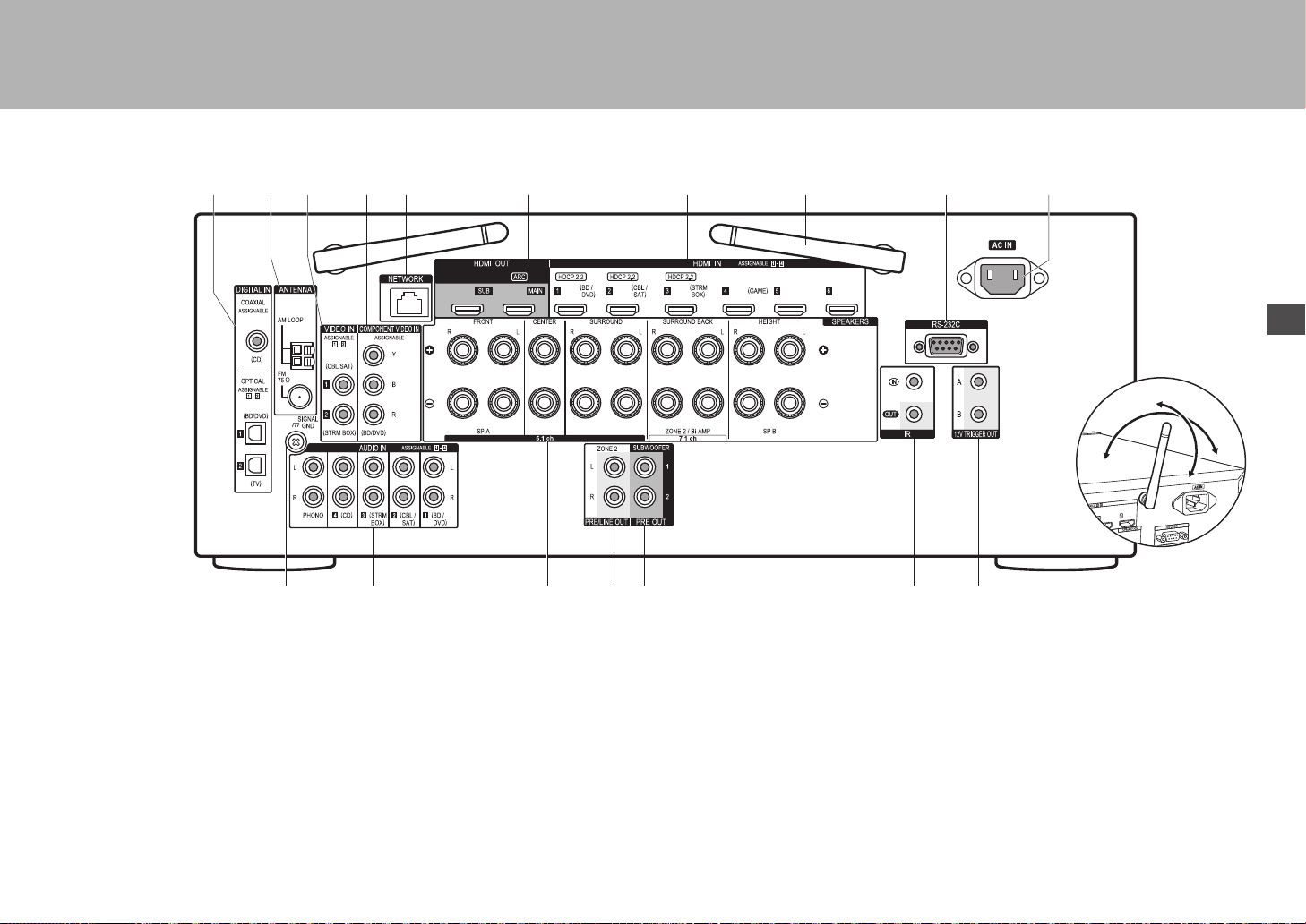
27
Es
> Antes de empezar > Conexión > Configuración > Reproducción > Nombres de las piezas
Panel trasero
1. Conectores DIGITAL IN OPTICAL/COAXIAL: Introduzca
señales de audio digital desde un componente AV o un
TV con un cable óptico digital o un cable coaxial digital.
2. Terminal ANTENNA AM LOOP/FM 75Ω: Las antenas
suministradas están conectadas.
3. Conectores VIDEO IN: Introduzca señales de vídeo de
un componente AV con un cable de vídeo analógico.
4. Conectores COMPONENT VIDEO IN: Introduzca señales de vídeo de
un componente AV con un cable de vídeo componente.
5. Puerto NETWORK: Conecte con la red a través de un
cable Ethernet.
6. Conectores HDMI OUT: Transmita señales de vídeo y
señales de audio con un cable HDMI conectado a un
monitor como un TV o un proyector.
7. Conectores HDMI IN: Transmita señales de vídeo y señales de
audio con un cable HDMI conectado a un componente AV.
8. Antena inalámbrica: Se usa para la conexión Wi-Fi o al
utilizar un dispositivo habilitado con BLUETOOTH. Ajuste
los ángulos de acuerdo con el estado de la conexión.
9. Puerto RS-232C: Para la conexión con el sistema de
control del hogar.
10.
AC IN: El cable de alimentación suministrado está
conectado.
11.
Terminal SIGNAL GND: Está conectado el cable de
puesta a tierra de la tornamesa.
12.
Conectores AUDIO IN: Introduzca la señal de audio de
un componente AV con un cable de audio analógico.
13.
Terminales SPEAKERS: Conecte los altavoces con
cables de altavoz.
14.
Conector ZONE 2 PRE/LINE OUT: Transmita señales de
audio con un cable de audio analógico a un
preamplificador principal o a un amplificador de potencia
en una habitación separada (ZONE 2).
15.
Conector SUBWOOFER PRE OUT: Conecte un
subwoofer con alimentación propia con un cable de
subwoofer. Se pueden conectar hasta dos subwoofers
con alimentación propia. Se emite la misma señal desde
cada uno de los conectores SUBWOOFER PRE OUT.
16.
Puerto IR IN/OUT: Le permite conectar un kit de mando
a distancia multihabitación.
17.
Conectores 12V TRIGGER OUT A/B: Le permite
conectar un dispositivo con conector de entrada de
gatillo de 12V para habilitar el funcionamiento enlazado
entre el dispositivo y la unidad.
1211 1413
109
8
8
1
23 5 764
15 16 17
180°
90°
SN29402194_VSX-301_BAS_Es.book 27 ページ 2016年1月6日 水曜日 午前12時13分

28
> Antes de empezar > Conexión > Configuración > Reproducción > Nombres de las piezas
Mando a distancia
1. Botón Í: Enciende la unidad o la pone en modo de espera.
2. botones del selector de entrada: Cambia la entrada a reproducir.
3. Botón 21: Selecciona la entrada a reproducir.
4. Botón (AV ADJUST): Puede llevar a cabo los ajustes
comunes en la pantalla de la TV.
5. Botones del cursor y botón ENTER: Seleccione el elemento con
los cursores y pulse ENTER para confirmar su selección.
6. Botón : Muestra el Home.
7. Botones de volumen: Le permiten ajustar el volumen. Este botón
también cancela el modo silencioso.
8. Botón : Silencia el audio temporalmente. Pulse de nuevo para
cancelar el silencio.
9. Botones LISTENING MODE: Le permite seleccionar el modo de
audición.
Botones MAIN/ZONE 2: Controla la función multizona.
(El botón ZONE 3 no se usa con esta unidad.)
10.
Botón de reproducción: Utilizado para operaciones de
reproducción cuando se reproduce Music Server o un USB.
11.
Botón : Utilizado para operaciones de reproducción
repetida/aleatoria cuando se reproduce Music Server o un USB.
Botón CLEAR: Borra todos los caracteres que ha introducido al
introducir texto en la pantalla del TV.
12.
Botón (STATUS): Cambia la información en la pantalla.
13.
Botón : Regresa la pantalla al estado anterior.
14.
Botón MODE: Cambia la sintonización de una emisora entre la
sintonización automática y la sintonización manual.
15.
Botón +Fav: Registra una emisora de radio.
9
10
1
2
4
3
6
8
7
5
11
12
14
13
15
30°
30°
Aprox. 5 m
Pantalla
1. Puede iluminarse cuando se realizan operaciones con el selector de
entrada "NET" o "USB".
2. Se ilumina en las siguientes condiciones.
Z2: Cuando ZONE 2 está activado.
: Cuando se conecta mediante BLUETOOTH.
: Cuando se conecta mediante Wi-Fi.
NET: Cuando "NET" está seleccionado con el selector de entrada y la
unidad está conectada a la red. Parpadeará si la conexión a la red no
es correcta.
USB: Cuando "USB" está seleccionado con el selector de entrada y la
unidad está conectada por USB y el dispositivo USB está
seleccionado. Parpadea si el dispositivo USB no está conectado
correctamente.
HDMI: Cuando entran señales HDMI y la entrada HDMI está
seleccionada.
DIGITAL: Cuando entran señales digitales y la entrada digital está
seleccionada.
3. Se ilumina de acuerdo al tipo de señales digitales de entrada de
audio y al modo de audición.
4. Se ilumina en las siguientes condiciones.
TUNED: Recepción de radio AM/FM.
STEREO: Recepción de FM estéreo.
SLEEP: Cuando el temporizador de apagado está activado.
AUTO STBY: El modo de espera automático está activado.
5. El sistema de altavoces actualmente seleccionado se ilumina.
6. Se ilumina cuando se conectan unos auriculares.
7. Parpadea cuando se encuentra silenciado.
8. Muestra información varia sobre las señales de entrada.
9. Se enciende cuando ajusta el volumen.
10.
Visualización de altavoz/canal: Muestra el canal de salida que
corresponde al modo de audición seleccionado.
14
8
2 3
9
65 7
10
SN29402194_VSX-301_BAS_Es.book 28 ページ 2016年1月6日 水曜日 午前12時13分
29
Es
Información sobre licencias y marcas
comerciales
Manufactured under license from Dolby Laboratories. Dolby, Dolby Atmos,
Dolby Surround and the double-D symbol are trademarks of Dolby
Laboratories.
For DTS patents, see http://patents.dts.com. Manufactured under license from
DTS, Inc. DTS, the Symbol, DTS in combination with the Symbol, the DTS-HD
logo, and DTS-HD Master Audio are registered trademarks or trademarks of
DTS, Inc. in the United States and/or other countries. © DTS, Inc. All Rights
Reserved.
The terms HDMI and HDMI High-Definition Multimedia Interface, and the HDMI
Logo are trademarks or registered trademarks of HDMI Licensing LLC in the
United States and other countries.
The Wi-Fi CERTIFIED Logo is a certification mark of the Wi-Fi Alliance
®
.
AirPlay, iPad, iPhone, and iPod touch are trademarks of Apple Inc., registered
in the U.S. and other countries.
iPad Air and iPad mini are trademarks of Apple Inc.
“Made for iPod”, “Made for iPhone” and “Made for iPad” mean that an electronic
accessory has been designed to connect specifically to iPod, iPhone, or iPad,
respectively, and has been certified by the developer to meet Apple
performance standards. Apple is not responsible for the operation of this device
or its compliance with safety and regulatory standards.
Please note that the use of this accessory with iPod, iPhone or iPad may affect
wireless performance.
AirPlay works with iPhone, iPad, and iPod touch with iOS 4.3.3 or later, Mac
with OS X Mountain Lion or later, and PC with iTunes 10.2.2 or later.
Apple, Apple TV and Safari are trademarks of Apple Inc., registered in the U.S.
and other countries.
The BLUETOOTH
®
word mark and logos are registered trademarks owned by
Bluetooth SIG, Inc. and any use of such marks by Onkyo Corporation is under
license. Other trademarks and trade names are those of their respective
owners.
Onkyo Corporation does not guarantee BLUETOOTH compatibility between the
AV receiver and all BLUETOOTH enabled devices.
For compatibility between the AV receiver and another device with
BLUETOOTH technology, consult the device’s documentation and dealer. In
some countries, there may be restrictions on using BLUETOOTH devices.
Check with your local authorities.
Onkyo Corporation ne garantit pas la compatibilité BLUETOOTH entre l'ampli-
tuner AV et tous les appareils compatibles BLUETOOTH.
Pour assurer la compatibilité entre l'ampli-tuner AV et un autre périphérique à
technologie BLUETOOTH, consultez la documentation de l'appareil et le
vendeur. Dans certains pays, il peut exister des restrictions sur l'utilisation
d'appareils BLUETOOTH. Vérifiez auprès des autorités locales.
Onkyo Corporation no garantiza la compatibilidad BLUETOOTH entre el receptor
de AV y todos los dispositivos con tecnología BLUETOOTH.
Para obtener información sobre la compatibilidad entre el receptor de AV y otro
dispositivo con tecnología BLUETOOTH, consulte al distribuidor y la documentación
del dispositivo. En algunos países, es posible que el uso de dispositivos
BLUETOOTH esté restringido. Consulte con las autoridades locales.
PANDORA, the PANDORA logo, and the Pandora trade dress are trademarks
or registered trademarks of Pandora Media, Inc. Used with permission.
Google Cast and the Google Cast badge are trademarks of Google inc.
The product with this logo is conformed to Hi-Res Audio standard defined by
Japan Audio Society. This logo is used under license from Japan Audio Society.
This product is protected by certain intellectual property rights of Microsoft. Use
or distribution of such technology outside of this product is prohibited without a
license from Microsoft.
Windows and the Windows logo are trademarks of the Microsoft group of
companies.
QR Code is a registered trademark of DENSO WAVE INCORPORATED.
“x.v.Color” and “x.v.Color” logo are trademarks of Sony Corporation.
DSD and the Direct Stream Digital logo are trademarks of Sony Corporation.
MPEG Layer-3 audio coding technology licensed from Fraunhofer IIS and
Thomson.
“All other trademarks are the property of their respective owners.”
“Toutes les autres marques commerciales sont la propriété de leurs détenteurs
respectifs.”
“El resto de marcas comerciales son propiedad de sus respectivos
propietarios”.
DESCARGO DE RESPONSABILIDAD
A través de este dispositivo podrá enlazar otros servicios o sitios web que no
están bajo control de ninguna compañía que ha designado, fabricado o
distribuido este dispositivo ni sus filiales (colectivamente, “Compañía”). No
tenemos control alguno sobre la naturaleza, contenido y disponibilidad de
dichos servicios. La inclusión de algunos enlaces no implica necesariamente
una recomendación o aprobación de los puntos de vista expresados en los
mismos.
Toda la información, contenido y servicios disponibles a través de este
dispositivo pertenecen a terceros y están protegidos por derechos de autor,
patentes, marcas comerciales y/u otras leyes de propiedad intelectual de los
países aplicables.
La información, contenido y servicios proporcionados a través de este
dispositivo son solamente para uso personal, sin fines de lucro. La información,
contenido o servicios no podrán ser usados de ninguna otra manera más que
la aprobada previamente por el propietario del contenido o proveedor de
servicio.
No podrá modificar, copiar, republicar, traducir, explotar, crear trabajos
derivados, cargar, publicar, transmitir, vender ni distribuir de ninguna manera
cualquier información, contenido o servicios disponibles a través de este
dispositivo, a menos que esté expresamente autorizado por los derechos de
autor, patente, marca comercial y/o titular de propiedad intelectual, incluyendo,
aunque sin limitación, al propietario del contenido o proveedor de servicios.
EL CONTENIDO Y SERVICIOS DISPONIBLES A TRAVÉS DE ESTE
DISPOSITIVO SON PROPORCIONADOS “TAL COMO ESTÁN”.
LA COMPAÑÍA NO GARANTIZA LA INFORMACIÓN, EL CONTENIDO NI LOS
SERVICIOS PROPORCIONADOS DE ESTE MODO, YA SEA EXPRESA O
IMPLÍCITAMENTE, PARA NINGÚN PROPÓSITO.
LA COMPAÑÍA RECHAZA EXPRESAMENTE CUALQUIER GARANTÍA,
EXPRESA O IMPLÍCITA, INCLUYENDO, PERO NO LIMITADO A, LAS
GARANTÍAS DE TÍTULO, NO VIOLACIÓN, COMERCIALIZACIÓN O
ADECUACIÓN PARA UN PROPÓSITO EN PARTICULAR.
La Compañía no representa ni garantiza de ninguna forma, expresa o
implícitamente, la integridad, precisión, validez, legalidad, confiabilidad,
aplicabilidad o disponibilidad con respecto a la información, contenido o
servicios disponibles a través de este dispositivo. La Compañía no se hace
responsable, ya sea por contrato o agravio, incluida la negligencia o
responsabilidad civil, de cualquier daño directo, indirecto, especial, incidental o
consecuente o de cualquier otro daño resultante de o en conexión con
cualquier información contenida, o como resultado del uso de cualquier
contenido o servicio proporcionado por usted o terceros, aun cuando la
Compañía ha sido avisada sobre la posibilidad de tales daños, ni tampoco la
Compañía se hará responsable por reclamos de terceros en contra de los
usuarios de este dispositivo o de terceros.
En ningún caso la Compañía será responsable de, sin limitar la generalidad de
lo anterior, cualquier interrupción o suspensión de cualquier información,
contenido o servicio disponible a través de este dispositivo. La Compañía,
tampoco se hace responsable por el servicio del cliente relacionado con la
información, contenido y servicios disponibles a través de este dispositivo.
Cualquier pregunta o consulta de servicio relacionada con la información,
contenido o servicios debe realizarse directamente a los propietarios del
contenido y proveedores de servicio.
®
SN29402194_VSX-301_BAS_Es.book 29 ページ 2016年1月6日 水曜日 午前12時13分

30
body2_spa.fm 30 ページ 2016年1月6日 水曜日 午前12時20分

31
Es
body2_spa.fm 31 ページ 2016年1月6日 水曜日 午前12時20分

*29402194*
F1601-0
SN 29402194
Корпорация О энд Пи
2-3-12, Яэсу, Чуо-ку, г. Токио, 104-0028, ЯПОНИЯ
<Germany>
Hanns-Martin-Schleyer-Straße 35, 47877 Willich, Germany
Tel: +49(0)2154 913222
<UK>
Anteros Building, Odyssey Business Park, West End Road, South Ruislip,
Middlesex, HA4 6QQ United Kingdom
Tel: +44(0)208 836 3612
<France>
6, Avenue de Marais F - 95816 Argenteuil Cedex FRANCE
Tel: +33(0)969 368 050
2-3-12 Yaesu, Chuo-ku, Tokyo 104-0028 JAPAN
<U.S.A.>
18 PARK WAY, UPPER SADDLE RIVER, NEW JERSEY 07458, U.S.A.
Tel: 1-201-785-2600
Te l: 1-844-679-5350
Register your product on
http://www.pioneerelectronics.com (US)
http://www.pioneerelectronics.ca (Canada)
Enregistrez votre produit sur :
http://www.pioneerelectronics.com (États-Unis)
http://www.pioneerelectronics.ca (Canada)
© 2016 Onkyo & Pioneer Corporation. All rights reserved.
© 2016 Onkyo & Pioneer Corporation. Tous droits de reproduction et de traduction réservés.
“Pioneer” and “ELITE” are trademarks of Pioneer Corporation, and are used under license.
Printed in Malaysia / Imprimé en Malaisie / Напеча
тано в Малайзии
SN29402194_VSX-301_BAS_En.book 32 ページ 2016年1月6日 水曜日 午前12時5分