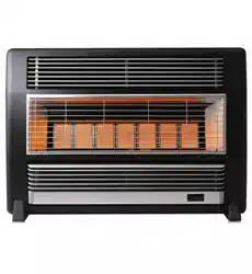
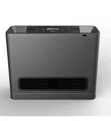
Everdure BRFNGBM Brigadier Gas Radiant Convection Natural Gas Heater
Product's Documents
Below are documents related to this product, you can read online or download:
User Manual
User Manual
- User Manual - (English) Read Online | Download pdf
- BRFNGBM - Everdure - Specifications Sheet - (English) Download