Loading ...
MULTI-GANG APPLICATION
In multi-dimmer installations, the reduction of the dimmer’s capacity may
be required. Refer to the chart for maximum load per dimmer.
NOTE: No derating is required for LED or CFL bulb applications.
If installing the dimmer in a single gang application, proceed with the
INSTALLING YOUR DIMMER section. If installing Dimmer in a
multi-gang application, proceed as follows:
INSTALLING DIMMER BY ITSELF
OR WITH MULTI-GANG
TOOLS NEEDED TO INSTALL YOUR DIMMER
Slotted/Phillips Screwdriver Electrical Tape Pliers
Pencil Cutters Ruler
Changing the color of your Dimmer:
Your dimmer comes with two color options. To change color of the face
proceed as follows:
1
2
Insert top tabs and
press in bottom tabs
to attach
Push in sides at bottom
tabs and pull outward to
release
MAXIMUM LOAD PER DIMMER FOR MULTI-GANG
More than 2 Gang
500W
Two Gang
500W
Single
600W
Load
Incand
INTRODUCTION
FEATURES
WARNING: TO AVOID FIRE SHOCK OR DEATH; TURN
OFF POWER at circuit breaker or fuse and test that power
is off before wiring!
Step 1
IMPORTANT: For 3-Way applications, note that one of the screw terminals
from the old switch being removed will usually be a different color (Black)
or labeled Common. Tag that wire with electrical tape and identify as the
Common (Line or Load) in both the dimmer wall box and remote wall box.
INSTALLING YOUR DIMMER
NOTE: Use check boxes when Steps are completed.
/./&&
/./&&
/./&&
/./&&
/./&&
/./&&
/./&&/./&&
/./&&
/./&&
/./&&
/./&&
Identifying your wiring application (most common):
NOTE: If the wiring in your wall box does not resemble any
of these configurations, consult an electrician.
Step 2
2
4
3
1
Single Pole
1. Line (Hot)
2. Neutral
3. Ground
4. Load
3-Way
1. Line or Load
(see important
instruction)
2. Neutral
3. Ground
4. First Traveler – note color
5. Second Traveler – note color
2
4
1
5
3
RATINGS
Incandescent - 600W - 120VAC, 60Hz
LED/CFL - 300W - 120VAC, 60Hz
3-Way Wiring with DD00R Matching Remote
(with LED) Application:
Cut
(if necessary)
5/8"
(1.6 cm)
Strip Gage
(measure bare
wire here)
Preparing and connecting wires:
This dimmer can be wired using side wire terminal screws
or through backwire openings. Choose appropriate wire
stripping specifications accordingly.
Step 3
Back Wire Connection
Back wire openings accept
#14-12 AWG solid copper
wire only.
• Make sure that the ends of the wires from the wall box are
straight (cut if necessary).
• Remove insulation from each wire in the wall box as shown.
• For Single-Pole Application, go to Step 4a.
• For 3-Way Matching Remote (with LEDs) Application, go to Step 4b.
Side Wire Connection
Side wire terminals accept
#14-12 AWG solid copper
wire only.
For non-standard wiring applications, refer
to Wire Connector and Conductor Size Chart
1 - #12 w/ 1 to 3 #14, #16 or #18
2 - #12 w/ 1 or 2 #16 or #18
1 - #14 w/ 1 to 4 #16 or #18
2 - #14 w/ 1 to 3 #16 or #18
WIRE CONNECTOR / # OF COND.
COMBINATION CHART
WIRING DIMMER:
Connect wires per WIRING DIAGRAM as follows:
NOTE: The DH6HD dimmer requires a neutral connection.
• Green or bare copper wire in wall box to Green dimmer
terminal screw.
• Line Hot wall box wire to Black dimmer terminal screw.
• Load wall box wire to Red dimmer terminal screw.
• Neutral wall box wire to White dimmer terminal screw.
• Yellow/Red dimmer terminal screw should have Red insulation
label affixed.
NOTE: If insulating label is not affixed to Yellow/Red dimmer
terminal screw, use electrical tape to cover.
• Proceed to step 5.
Dimmer
Insulating
Label
Black
Load
Hot (Black)
BK
Line
120 V
AC,
60Hz
Neutral (White)
RD
WH
YL/RD
White
Green
Ground
Terminal
Screw marked
Black (BK)
Terminal
Screw marked
Red (RD)
Terminal Label:
Use terminal for 3-way or more applications only.
For single-pole applications, DO NOT remove label.
Terminal
Screw marked
Yellow/Red
(YL/RD)
4
BK
WH
RD
YL/RD
1
3
2
Single Pole Wiring Application:
Step 4a
Step 4b
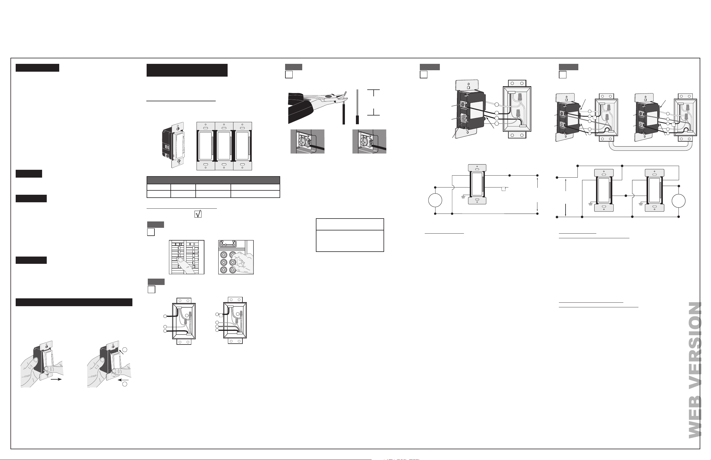
WIRING DIMMER
(wall box with load connection):
Connect wires per WIRING DIAGRAM as follows:
NOTE: The DH6HD dimmer must be installed in a wall box that has a Load
connection. The dimmer also requires a neutral connection.
• Green or bare copper wire in wall box to Green terminal screw.
• Load wall box wire identified (tagged) when removing old switch to
dimmer terminal screw marked "RD".
• First Traveler Line Hot to dimmer terminal screw marked "BK".
• Remove Red insulating label from terminal screw marked "YL/RD".
• Second Traveler wall box wire (note color as above) to dimmer terminal
screw marked "YL/RD". This traveler from the dimmer must go to the
terminal screw on the remote marked "YL/RD".
• Neutral wall box wire to White dimmer terminal screw.
WIRING MATCHING REMOTE
(wall box with Line Hot connection):
Connect wires per WIRING DIAGRAM as follows:
NOTE: The matching remote must be installed in a wall box with a Line
Hot connection and a Neutral connection. A Neutral wire to the matching
remote needs to be added as shown. If you are unsure about any part of
these instructions, consult an electrician.
NOTE: Maximum wire length from dimmer to all installed remotes cannot
exceed 300 ft (90m).
• Green or bare copper wire in wall box to Green terminal screw.
• Line Hot (common) wall box wire identified (tagged) when removing old
switch and First Traveler to remote terminal screw marked "BK".
• Second Traveler wall box wire from dimmer to remote terminal screw
marked "YL/RD" (note wire color). This traveler from the remote must
go to the terminal screw on the dimmer marked "YL/RD".
• Line Neutral wall box to remote terminal screw marked "WH".
NOTE: To synchronize LEDs between a Decora
®
digital remote and
the Decora
®
DH6HD dimmer, a dim up or dim down command must be
pressed on the remote.
• Proceed to Step 5.
Hot (Black)
Neutral (White)
Dimmer
Matching Remote (w/LEDs)
YL/RD
RD
YL/RD
WH BK
BK
Black
White
Line
120VAC, 60Hz
Green
Ground
Green
Ground
WH
Load
DimmerMatching Remote (with LED)
Terminal
Screw
marked
Black
(BK)
Terminal
Screw marked
Red (RD)
Terminal
Screw marked
White (WH)
Terminal
Screw
marked
Yellow/
Red
(YL/RD)
Terminal
Screw marked
Red (RD)
3
5
Neutral to Terminal
Screw marked
White (WH)
2
3
5
WH
BK
RD
YL/RD
BK
RD
YL/RD
1
4
4
1
Terminal
Screw
marked
Black
(BK)
Terminal
Screw
marked
Yellow/
Red
(YL/RD)
WH
2
REQUIRED
WARNINGS AND CAUTIONS
• TO AVOID FIRE, SHOCK, OR DEATH; TURN OFF POWER at circuit breaker or fuse and test that power is off before wiring!
• TO AVOID FIRE, PERSONAL INJURY OR PROPERTY DAMAGE, DO NOT install to control a receptacle, a motor, or a transformer operated appliance.
• To be installed and/or used in accordance with electrical codes and regulations.
• If you are unsure about any part of these instructions, consult an electrician.
• Use with incandescent, or 120V halogen fixtures only. Use a Leviton electronic low voltage dimmer to control electronic (solid state) low voltage transformers.
•
The Decora
Smart
TM
DH6HD dimmer is not compatible with standard 3-way or 4-way switches. It must be used with up to 4 Decora
®
Digital DD00R-DL remotes for multi-location dimming.
• Maximum wire length from dimmer to all installed remotes cannot exceed 300 ft.
• Save this instruction sheet. It contains important technical data along with testing and troubleshooting information which will be useful after installation is complete.
WARNINGS AND CAUTIONS
• Dimmer may feel warm to the touch during normal operation.
• Recommended minimum wall box depth is 2-3/4".
• Use this dimmer with copper or copper clad wire only.
• Use with compatible dimmable LED, CFL bulbs, incandescent or 120V halogen fixtures only. For a list of compatible LED and CFL bulbs refer to www.leviton.com.
•
DO NOT mix bulb types when multiple bulbs are used with one dimmer. All bulbs shall be either LED; CFL or incandescent. Using the same make/model of each bulb will enhance dimmer performance.
• Leviton HomeKit-enabled accessories rely on Wi-Fi
®
communication. Increasing the number of Wi-Fi
®
accessories can affect Wi-Fi
®
performance. Consult the network’s wireless access point
specifications to determine the maximum number of supported Wi-Fi
®
accessories. For installations with a large number of Leviton HomeKit Wi-Fi
®
accessories, a high performance wireless
access point capable of supporting a large number of accessories may be required.
• The Decora Smart
TM
Dimmer is HomeKit-enabled using Wi-Fi
®
technology for residential applications
• Compatible with the Leviton Decora Smart Home app as well as
other HomeKit-enabled apps
• Soft fade ON/OFF
• ON/OFF LED and Brightness level LED
•
Over The Air (OTA) firmware updates via the Leviton
Decora Smart
Home app
• Single pole or three way compatible
• Ease of installation - No new wiring
DI-000-DH6HD-02A
Leviton’s Decora Smart
TM
accessories are designed to streamline home
control with other HomeKit-enabled accessories. Apple HomeKit
TM
technology provides an easy, secure way to control HomeKit-enabled
accessories using Siri voice control on your iPhone or iPad. After
installing your Decora Smart
TM
Dimmer, configure it from the Leviton
Decora Smart Home app with just a few simple steps.
WARNING: TO AVOID FIRE, PERSONAL INJURY OR DEATH DO NOT
USE the remote for the control of high power heating appliances such
as portable heaters. There can be some unexpected consequences if
not used with care. For example, an empty coffee pot can be remotely
turned on. If that should happen, your coffee pot could be damaged from
overheating. If an electric heater is turned on by remote control while
clothing is draped over it, a fire could result. This device will not control
lighting that is used with electronic low-voltage and high frequency power
supply transformers, nor high pressure discharge lamps (HID lighting).
This includes mercury-vapor, sodium vapor and metal halide lamps.
Decora Smart
TM
accessories are ideal for living rooms, bedrooms,
kitchens, dining rooms, home offices, outdoor lighting or anywhere full
control of lighting is desired.
• Wi-Fi
®
Network
• Free Leviton Decora Smart Home app
• Controlling this HomeKit-enabled accessory away from home
requires an Apple TV (3rd generation or later) with Apple TV
software 7.0 or later and an iPhone or iPad with iOS 8.1 or later
WEB VERSION